Input Output Interface
Open the original PDF document
View PDF

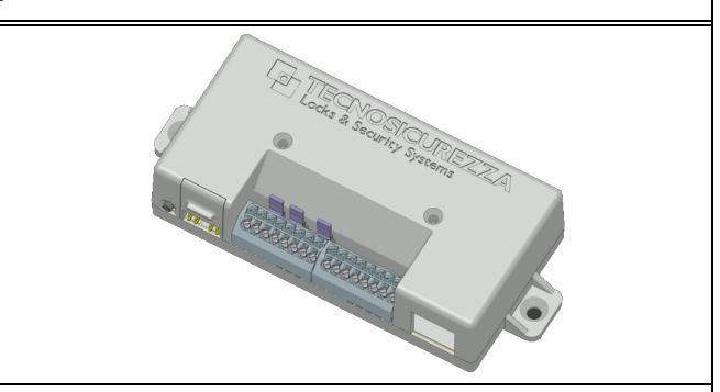
T9355: Input/output interface
T9355 includes:
- Plastic box
- Reset button
- Alarm signals terminals
- Keypad/lock connectors
- Jumpers NC/NO
| RS485 PROTOCOL | 1. | GND |
|---|---|---|
- 3. RS485 -
OUTPUTS *
Dry contacts
Normally open/closed
Max 30Vdc , 1A
Max 60Vdc , 300mA
Max 125Vac≂, 500mA
Max 50Vdc , 200mA
- 2. RS485 +
- 4. RS485 BUSY
- 5. OUTPUT 1 (Silent alarm)
- 6. OUTPUT 1 (Silent alarm) 7. OUTPUT 2 (Penalty)
- 8. OUTPUT 2 (Penalty)
INPUT *
Not isolated
Active low
Short circuit between INPUT and GND to activate the signal. (do not power the Input)
Max 50Vdc , 20mA
Vil Max= 0,5Vdc Vih Min= 3,0Vdc
VDC OUTPUT
- 9. GND (Remote block)
- 10. INPUT 1 (Remote block)
- 11. GND (Remotely managed)
- 12. INPUT 2 (Rem. managed)
9Vdc OUT, max 100mA 13. GND
POWER SUPPLY
12Vdc-24Vdc (1A)
- 14. 9V OUT+
16. PWR IN +
15. GND
* Inputs and outputs can be changed by the TechMaster setup software. The values shown inside the brackets must be considered just as factory values.
RESET BUTTON KEYPAD & LOCK RESISTOR 485 TERMINATION NO/NC NO/NC

The connection and installation of the interface has to be done by qualified personnel properly trained.
RESET PROCEDURE .
- 1) Connect the reset-box to any of the keypad/lock connector on the interface.
- 2) Push and release the reset button. The LED will begin to blink slowly.
- 3) Disconnect the reset-box from the interface.
- 4) Push and release again the reset button. The LED will turn on for a few seconds then it will turn off.
- 5) The interface is now reset and it is ready to be installed on the system.
INSTALLATION PROCEDURE .
- 1) Make sure that the interface is reset.
- 2) Connect the interface to the keypad.
- 3) Open the lock 1 and keep the bolt open.
- 4) Enter in the configuration menu.
- 5) Select 'Install I/O interface' submenu.
- 6) Enter Master code to complete the installation procedure.
- 7) The interface is now installed and resdy to work.
- 8) When using the interface in 'RS485 mode', make sure the ID is set correctly.
II_T9355_05_eng Page 1 of 2