ITL 950C Manual
Open the original PDF document
View PDF
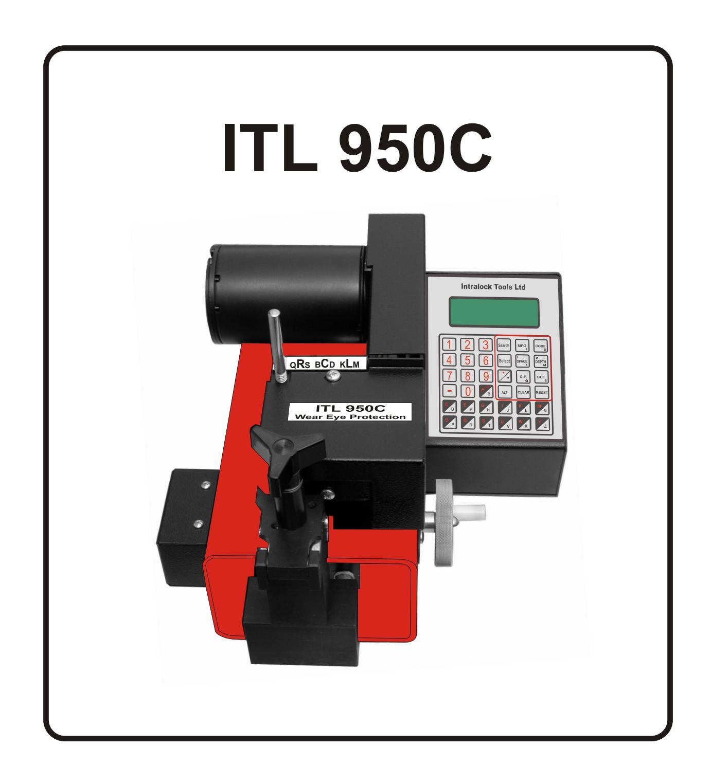
THE ITL 950C COMPUTER KEY MACHINE Operations Manual
ITL 950C Operating Manual TABLE OF CONTENTS
| INTRODUCTION | PAGE | |
|---|---|---|
| * Table of contents | 1 | |
| * Specifications | 2 | |
| * Key Functions | 3 | |
| OPERATION | ||
| * Starting the ITL950C | 4 | |
| * Selecting a Manufacturer | 4 | |
| * Entering a Code | 4 | |
| * Cutting a Key | 4 | |
| * Calibrating the ITL950C. | 5 | |
| * Setting Correction Factor | 6-7 | |
| III CUSTOM CONFIGURATION | ||
| * Setting the default manufacturer ID | 8 | |
| * Setting units (metric – inches). | 8 | |
| * Setting default cut rate | 8 | |
| * Setting display | 8 | |
| * Setting the display contrast | 8 | |
| * Setting Custom Flat Widths | 9 | |
| * Flat width table | 9 | |
|
IV
CREATING A CUSTOM ID TABLE |
||
| * Selecting ID To Be Created | 10 | |
| * Enabling and Disabling Pause | 10 | |
| * Setting Tip Type | 10 | |
| * Table of reference points | 10 | |
| * Selecting a Flat | 10 | |
| * Selecting Insert Number | 10 | |
| * Enabling an Extended Table | 11 | |
| * Setting Maximum Space | 11 | |
| * Setting Maximum Depth | 11 | |
| * Setting Minimum Depth | 11 | |
| * Setting Values In Space Table | 12 | |
| * Setting Values In Depth Table | 12 | |
| * Special cutting instructions | 13 | |
| VI SETTING SERIAL PORT PARAMETERS | ||
| * Setting Serial Port Baud Rate | 14 | |
| * Error Messages | 14-15 | |
| VII SPECIAL INSTRUCTIONS | ||
| * Half depth mode | 07 | |
| * Flow chart for Medeco Biaxial | 16 | |
| * Generating a master key system | 17 | |
MACHINE SPECIFICATIONS
Operating Voltage - 120 Volts AC. 2 Amps 60 Hz.
- 12 Volts DC. 10 Amps
Operating Current - AC 1.5 Amp PK. 25 Idle. DC 10 Amp. PK. 1 Idle.
Operating Frequency - 60 Hertz/DC.
Motor Horsepower - 1/8 H.P.
Cutter Speed - 1600 R.P.M.
Motor Bearing Type - Sealed Roller Bearing
Standard Codes - UP TO 800
Custom Codes - 160 (User Modified)
User Definable Flats - 10 with range of 0.001" to 0.140"
Display Format - 4 Line 20 Character Alpha-Numeric
Micro Power LCD
Keyboard Type - 20 Key Sealed Membrane
Computer Interface - RS232C 75-9600 Baud
- Parallel IBM compatible
Repeatable Accuracy - (+/-) 0.002"
Weight - 48 Lbs. Packaged
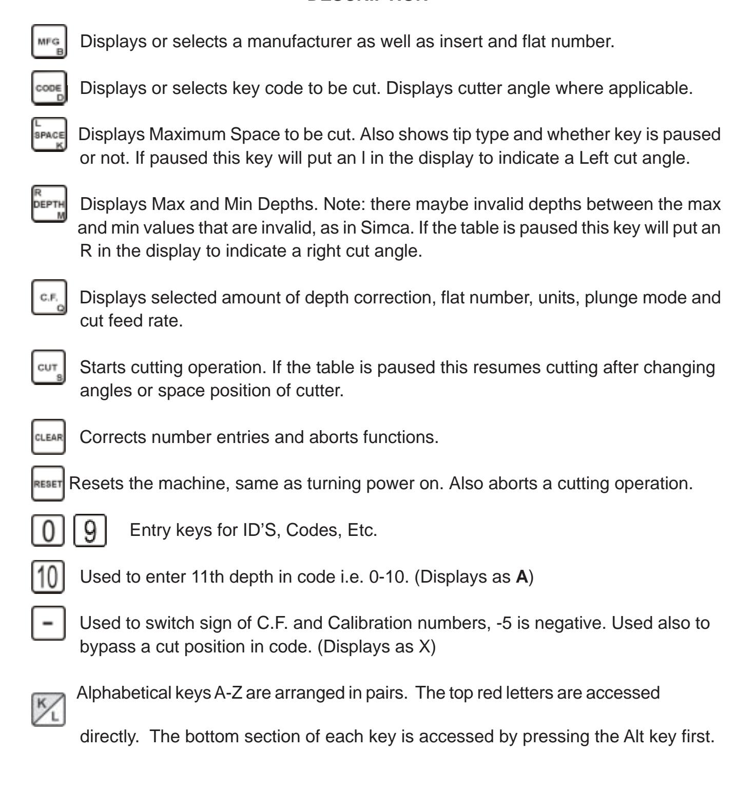
KEY FUNCTIONS
DESCRIPTION
STARTING THE ITL 950C
The, ITL950C should be plugged in to a switch operated power bar with surge suppression. Check serial plate for correct machine voltages and current requirements. Turn on the power switch located on the back of machine. Follow instructions on the display. (Move vise to right or left.)
12-VOLT POWER INVERTERS
THE USE OF A POWER INVERTER IS NOT RECOMMENDED WITH THE ITL950C . There is a problem of a stable voltage supply with most inverters. When the voltage drops the ITL950C will try to reset and can damage the electronics. A low voltage does not matter with a drill or drive motor but does matter to the ITL950C. WE RECOMMEND CONNECTING THROUGH
A 20 Amp FUSE TO THE VEHICLE 12-VOLT BATTERY FOR MOBILE USE.
SELECTING A MANUFACTURER Press the key to display the current lD . number. To load a new lD. number, enter the required ID number and . To select Manufacturer 167 (WEISER), press then . The ITL950C will display MANUFACTURER 167 INSERT 2 FLAT 8, indicating the new ID is accepted and has loaded the key specifications.
CUTTING A DIRECT ENTRY CODE (key cuts)
To load a new direct entry code press the desired cuts then press . The ITL950C will display the desired cuts, indicating it has accepted the cuts.
CUTTING A KEY
In this example we will use MFG number 167 WEISER and cuts 42312. 1) Select Manufacturer 167 by pressing followed by The ITL950C will display MANUFACTURER 167 INSERT 2 FLAT 8, indicating the new ID is accepted and it has loaded the key specs. Insert 2 should be used to hold the blank and Flat 8 is the width of each cut. 2) Select key code 42312 by pressing keys then . The ITL950C will display CODE 42312 indicating the code has been accepted. 3) Using insert 2 put a blank in the vice. Flip up the shoulder reference arm to position the key but remember to put it down before cutting. Tighten the vice and press then turn the space handle clockwise until the bar graph disappears and the numbers pass thru "0000". The cutter motor will start and the space handle motion should be reversed to counter clockwise. Continue turning the handle, at about one revolution per second, until the cuts are completed and the cutter motor stops. **Do not leave the machine motor running when not cutting a key as this may damage the control transistors.
CUTTING A CAR KEY TO CODE
To cut the sample car key code KZ92 press then then move the currsor using the up down arrow key to GM 10C 95+ and press . Insert the suggested insert 1FL and install the suggested key P1106 or equivalent. Now press Turn the handle clockwise until the blocks disappear and the numbers count down to 0 and the cutter starts. Now turn the handle counterclockwise untill the first side of the key is cut and the cutter stops. Turn the key over and press cut, turn the handle clockwise until the blocks disappear and the numbers count down to 0 and the cutter starts. Now turn the handle counterclockwise untill the second side of the key is cut.
ALWAYS MAKE SURE THE CUTTER HAS STOPPED BEFORE REMOVING A KEY MAKE SURE THE MOTOR IS OFF BEFORE REMOVING THE KEY.
CALIBRATING THE ITL950C
NOTE Ill IT IS POSSIBLE TO RUN THE CUTTER INTO THE VICE WITH IMPROPER CALIBRATION. BE CERTAIN OF DEPTH CALIBRATION. YOU MAY ABORT THE CUTTING OPERATION AT ANY TIME BY PRESSING THE RESET KEY. THIS WILL STOP THE CUTTER AND RETURN THE KEY TO THE IDLE POSITION. DO NOT AT ANY TIME ALLOW THE CUTTER TO TOUCH THE VICE, AS IT WILL DAMAGE THE CUTTER.
TO CHECK CALIBRATIONS
First select MFG 391 this is "Schlage". Next, place insert #2 in the vice jaw and slide a blank onto it. Push the key along the top of the insert until the bottom shoulder comes up hard against the insert. Check the right hand side of the vice. Make sure the insert is tight against the stop screw. Tighten the vise and press . When the cut is finished, remove the key and measure the distance from the back of the blank to the bottom of the cut with a micrometer caliper. Subtract the reading you get from the .335 thousand depth it should be and note the number down. Measure the distance from the bow of the key to the center of the first cut. As above, subtract the reading from the .231 thousand space it should be.
TO ADJUST CALIBRATIONS
Press the keys to enter the EDIT mode and then press . The display will show EDIT CALIBRATION. Press . Now the display will show ADJUST DP BY 000. If in our sample our depth reading is .340, .335 minus .340, equals -.005. On the keypad enter . Now the display will read –005. . To return to EDIT CALIBRATION, push the key twice, and then press the key. In our sample, if the space reading is .229, subtract this from .231 and the answer is .003. Now press and the display will read 003. Press the key twice and follow display instructions to return to home.
Correct depth calibration is more critical than space calibration, but the more exact they both are, the better the resulting keys will work. Remember that the allowable range for calibration is from +0.127 inches to-0.127 inches. The machine is factory set for 0 calibration error so you must be careful not to enter a depth value that would allow the vise to contact the cutter. Double check your calibration numbers before entering them and if possible make small changes until you are familiar with this operation. All calibrations are done using the insert as the stop. When this has been completed, raise the reference arm up against the shoulder of the key to ensure that it has not been moved or bent out of position. The reference arm should make light contact with the blank shoulder, if not, loosen the two 5/32 allen head machine screws holding the reference block to the vice block and move the reference arm against the key shoulder and retighten the screws.
Menu of key temporary functions
- 1. Correction (depth).
- 2. Flat number (width of root of cut).
- 3. Cut mode (laser or normal)
- 4. Half depth mode ( cuts between current and next depth).
- 5. Plunge mode (cut entry method).
- 6. Cut feed rate (speed that plunge method uses).
- 7. Bypass home.
- 8. Units (inches or metric).
It should be noted if the machine is turned off, the key pressed or the manufacture
I.D. changed, all key functions revert to the default settings.
SETTING TEMPORARY DEPTH CORRECTION
1. The correction function affects the depth of all cuts. A negative correction factor makes cuts deeper while a positive correction factor makes cuts shallower. The range is from -.009 to +.009 inches in .001 inch steps. Press then a number from through . Use the key to indicate a negative value. Press to correct your entry and press to set the correction.
A special note regarding the correction function. If the resulting depth is out of the absolute limits of 0.110 to 0.465 inches, that cut will not be made.
CHANGING FLAT NUMBER
2. The flat number is used to select the width of the bottom of a cut. There are 10 possible flats to choose from and they are all user definable. The flats listed in the table on page 3 have been preset at the factory. Refer to setting custom flat widths in the Custom Configuration section for more details.
Press twice. The ITL950C will now display FLAT NUMBER (current flat). To change the flat number to 2, press , then to set the new flat number. The ITL950C will now display FLAT NUMBER 2, press to return to READY.
TEMPORARY CHANGE TO LASER CUT MODE
|
In the laser cut mode cuts are made from flat edge to flat
edge without the normal inbetween cut points. From the ready prompt push the C.F. key three times, the display will |
||
|---|---|---|
| read normal cut mode. Push the (-) key to toggle to the laser cut mode and back to the normal | ||
| cut mode. | ||
| HALF DEPTH MODE | ||
| 4. Press | four times. The ITL950C will now display HALF-DEPTH = NO This is the normal | |
| mode. Push | to switch to the half depth mode and all cuts will be made half way to the next | |
| depth. When cutting the key the second line will read < 1/2 Depth = on >. | ||
| PLUNGE CUT MODE | ||
| 5. Press | five times. The ITL950C will now display PLUNGE = NONE (Normal cut method) | |
| PLUNGE = ALL (for keys that require straight in and out movement of the cutter) Safety deposit or | ||
| flat steel. PLUNGE = FIRST (for keys that require a vertical entry in the first position to avoid cutting | ||
| the key shoulder). Press |
key to toggle to required function, press
to return to READY. CHANGING CUT RATE |
|
| 6. The cut rate is a number from 1 through 4 that defines how fast a blank is fed into the cutter. 1 is the | ||
| fastest rate and should work for most blanks. However if the cutter becomes dull or thick—blanks are | ||
|
used you may need to select a slower speed. To select a cut rate of 3, proceed as follows. Press the
key 6 times. The display will now read CUT FEED RATE (current rate) press and |
||
| , the display will now read CUT FEED RATE 3. Press |
to return to READY.
BYPASS HOME MODE |
|
|
7.
Press |
seven times. The ITL950C will now display BYPASS HOME = NO This will | |
| reset the space calibration after every cut. Press the | key to toggle to BYPASS HOME = | |
| YES this will temporarily turn off the space calibration. This can be used for impressioning locks | ||
|
faster. Press
to return to READY. |
||
| UNITS (METRIC OR INCHES) | ||
|
8.
Press |
eight times. The ITL950C will now display UNITS (INCHES OR METRIC). | |
|
Press
key to toggle. |
||
| CUSTOM EDIT MODE | ||
| Custom default entries using the | key remain in memory when the machine is reset or | |
turned off.
SETTING DEFAULT MANUFACTURER ID
The default or power on ID is the MFG ID number the machine selects when reset or turned on. As with any ID, it must be in the range of 1 through 960, and the table must be correct. It can be set by you and remains set until you select a different ID.
|
1)
Press the keys to enter the EDIT mode. The display will show EDIT. |
|---|
|
2)
Press the key to display the current default ID. To change the ID to 23, press |
|
followed by
. The ITL950C will display DEFAULT ID 23. |
|
3)
Press the key to return to the EDIT mode. Press the key and follow display |
| comands and the new ID will be displayed when the ITL950C completes the self-test sequence. |
| SETTING THE BAUD RATE |
| See page 14 for table and instructions. |
| UNITS (INCHES – METRIC) |
|
Press
and the key three times and the display will read |
|
UNITS = INCHES. To read the display in metric, press the
key. Press the key twice |
| and follow display instructions. |
|
SETTING DEFAULT CUT RATE
The default cut rate is a number from 1 through 4 that defines how fast the blank is fed into the cutter. 1 is the fastest rate and should work for most blanks however if the cutter becomes dull or thick blanks are used, you may need to select a slower speed. Proceed as follows to set the default cut rate. Press to enter the EDIT mode. Press four times to display CUT FEED RATE(current feed rate).To change the rate to 2, press The machine will now display CUT FEED RATE 2. Press and . Follow display |
| instructions and all plunge cuts will be made at cut rate 2. |
| SETTING DISPLAY MODE |
|
Press
to enter the EDIT mode. Press five times to display |
| BAR GRAPH DISPLAY MODE SELECTED or NUMERIC DISPLAY MODE SELECTED. Press |
|
key to toggle. Press the
key twice and follow display instructions. |
SETTING THE LCD DISPLAY CONTRAST
|
Press
to enter the EDIT mode. Press the key six times and |
|
|---|---|
|
the display will read SET LCD CONTRAST 9=DARK10=LIGHT. Press and hold the
key and |
|
|
the display will darken. Press and hold the
key and the display will lighten. Press the |
|
| key twice and follow the display instructions. |
RESET CODE (for factory use) SETTING CUSTOM FLAT WIDTHS
The flat width determines the width at the bottom of a cut. There are 10 possible flats to choose from and they are all user definable. The following section describes how to set your own flat width.
** CAUTION ** FLAT WIDTHS 1 THRU 8 ARE USED WITH THE MANUFACTURER ID'S AND CHANGING THESE FLAT WIDTHS WILL CAUSE WRONG FLAT WIDTHS TO BE CUT.
|
Press
to enter the EDIT mode. Press and and the |
|---|
|
display will show FLAT 1 = 014.
NOTE: Flat 1 is the flat width of the installed cutter and when |
| cutters are changed, flat 1 must be changed to match the flat width of the new cutter. Pressing |
| will step through all the 10 flats. To change a flat, enter the desired flat width and press |
| . For a table of flat numbers and widths refer to the table below. |
| FLAT WIDTH TABLE | ||
|---|---|---|
| FLAT | WIDTH | EQUIVALENT CUTTER |
| 1 | 0.014 INCH | CW1012 |
| 2 | 0.024 INCH | 37MC USE FOR ASSA |
| 3 | 0.044 INCH | CW1011 |
| 4 | 0.048 INCH | 14MC |
| 5 | 0.036 INCH | 4711 |
| 6 | 0.032 INCH | Assa |
| 7 | 0.070 INCH | 20MC |
| 8 | 0.090 INCH | CC100 |
| 9 | INCH | USER DEFINED WIDTH |
| 10 | INCH | USER DEFINED WIDTH |
Note: If a CW1011 cutter is installed, and the manufacture selected calls for a #1 or #2 flat the display will read the warning FLAT LESS THEN CUTTER INSTALLED.
CREATING A CUSTOM ID TABLE
There are 160 custom IDs you can change yourself the range is 801 to 960. They support the same features as the fixed IDs. The following sections explain how to create or edit your own custom ID. The last page of the manual contains a form that should (MUST) be completed before starting to create a new ID. Photocopy the last page there is only one.
NOTE: The following instructions are set to be followed in a consecutive manner and will not work properly on an individual basis. Pressing repetitively will cycle you to an individual function.
SELECTING ID TO BE CREATED
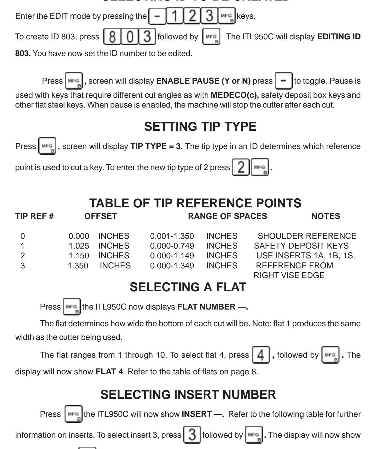
INSERT 3. Press to continue. Clear may be used to correct entries or return to edit mode.
DEPTH LIMITS FOR VISE INSERTS INSERT NUMBER OFFSET FROM TRUE 0 RANGE OF DEPTHS 1 0.000 INCHES 0.465 - 0.180 INCHES 2 0.035 INCHES 0.430 - 0.145 INCHES 3 0.070 INCHES 0.395 - 0.110 INCHES 4 0.100 INCHES 0.365 - 0.080 INCHES EXTENDED TABLE Press the ITL950C now displays EXTENDED TABLE Y/N Press to toggle. The table must be set to (Y) for keys requiring 11 or 12 spaces. When you select the extended table function, the ID # following the one you are currently editing will contain the extra spaces. For example if you were editing ID 803, and selected the extended table function, ID 804 would contain the 2 extra spaces. Note: You should not use ID 804 as a valid ID. When using the extended table use the maximum space value in the first table, in this case 803 should be set to 10 and all 10 spaces must be valid. Edi t the second ID in this case 804 as with any other custom ID however you need enter only spaces 1 and 2. Space 1 would be the 11th space in an extended ID and space 2 would the 12th space. MAXIMUM SPACE Press the ITL950C now displays MAXIMUM SPACE. The range is 1 to 10. To select a maximum space number of 7, press followed by . The display will now show MAXIMUM SPACE 7. The maximum space number is used to verify correct table set-up, define table limits and determine code length. Enter and for 10th space, not the key. MAXIMUM DEPTH Press , the ITL950C now displays MAXIMUM DEPTH . The range is 0 to 10 (not the key!). To select a maximum depth number of 8, press followed by . The display will now show MAXIMUM DEPTH 8 . The maximum depth number is used to verify correct table set-up, and define table limits. MINIMUM DEPTH
Press the ITL950C now displays MINIMUM DEPTH . The range is 0 to 9. To select a minimum depth number of 1, press followed by . The display now shows MINIMUM DEPTH 1. The minimum depth number is used to verify correct table set-up, and define table
limits. Press to return to EDIT.
NOTE: PARAMETER TABLE IS COMPLETE PLEASE REVIEW THE TABLE FOR ACCURACY.
To review the table, continue pressing the key until the display returns to EDIT.
SETTING VALUES IN SPACE TABLE
Press the ITL950C will display; SPACE 1 = (0000). Enter the desired space information in thousandths of and inch e.g. .250. Press on the keyboard, then press to set entry and to continue to SPACE 2 ect., until all space entries are completed. The ITL950C will automatically return to EDIT .
SETTING VALUES IN DEPTH TABLE
Press the ITL950C will display DEPTH 0 = ( - - - - ). Enter the desired depth information in thousandths of and inch e.g. .335. Press . Then to set entry and to continue to DEPTH 1=0000. Now continue to make entries until all depth entries are completed. The ITL950C will automatically return to EDIT .
Press key, the ITL950C will display PUSH "—" TO UPDATE TABLE, CLEAR TO CANCEL. Press key to set entries. Now follow display commands to return to default.
To sum up be sure your entries are all correct and should your new code fail to work as expected, DON'T PANIC, recheck the table and you will likely find an error in one of your entries.
To view or edit your entries press , display will read EDIT. Press , display will read EDITING ID 0803 continue to press to cycle through the new ID parameters. To review the numeric entries in the space file, press and , then continue pressing the key. To review the depth file, press the number set in the minimum depth setting and continue pressing the key through all depth settings.
Special Cutting Instructions
NOTE For nickel silver blanks our ITL MD1027 CARBIDE CUTTER should be used.
Cutting keys generated by Master Key Program
| Generate Master Key system. Follow instructions on page 17. |
|---|
|
Push
This will enable use of the Generated system. |
|
Select key number from printed chart Press (key number),
or continue to press |
| . to cycle through the generated system. |
|
Press
when desired key is displayed. |
General Motors
General Motors and other keys that have deep cuts close to the shoulder.
- 1. Input code in the regular fashion. 2. Push key four times, display will read PLUNGE = NONE 3. Push key twice to PLUNGE = FIRST . 4. Push key twice. Move vise right to 0000, the screen will now display CUT TO CONTINUE. Press , the cutter motor will start, wait until the cutter rests on the bottom of the cut.
- 5. Turn the handle counter clockwise to complete the remainder of the cuts in a regular fashion
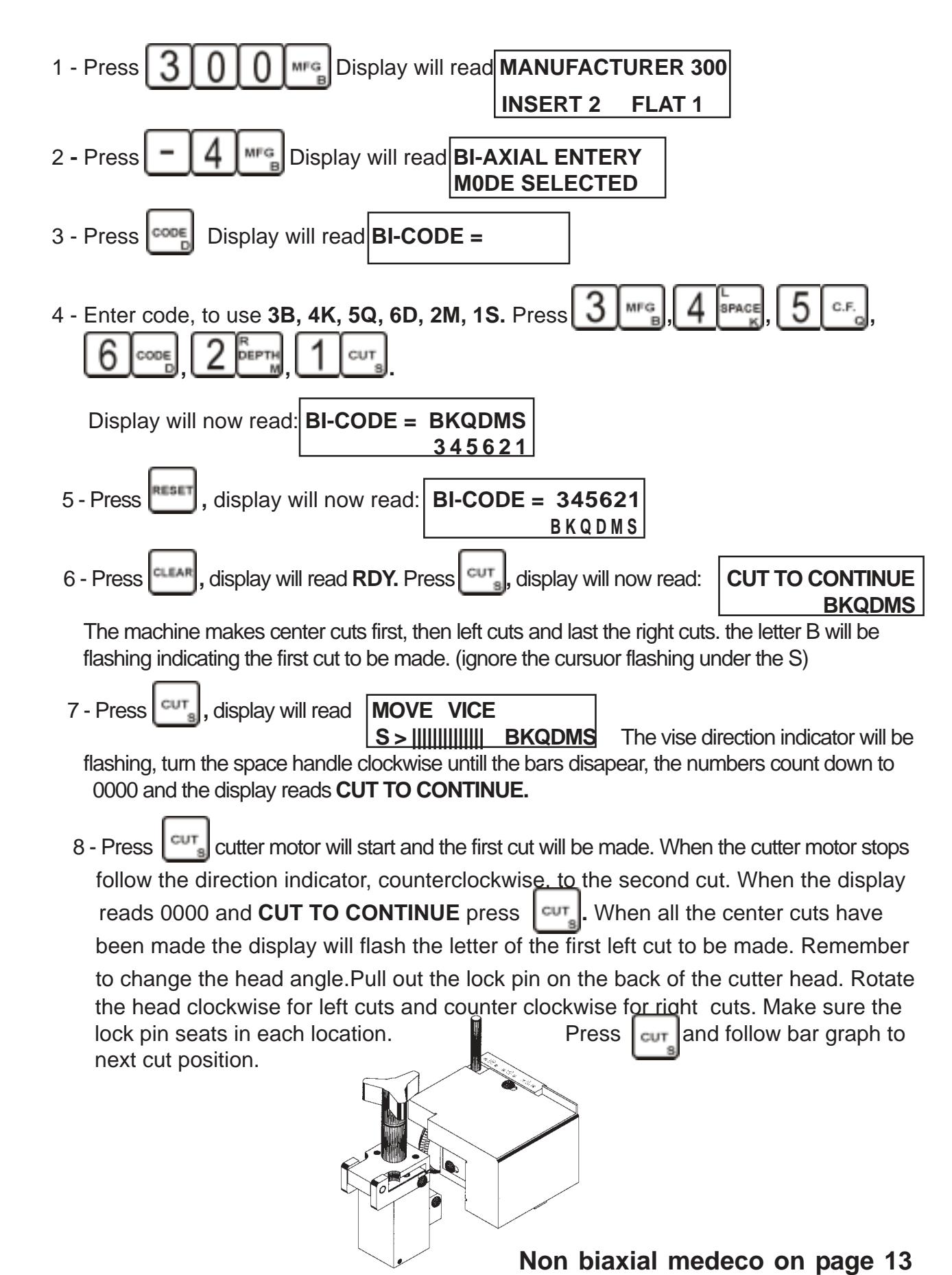
Non Biaxial Medeco ( MFG 298,299,302 )
Note CW1012 cutter should be installed for Medeco. 1 flat should be set to 14 thousands. To cut a key with a code 1 LEFT, 2 CENTER, 2 RIGHT, 1 CENTER, 2 LEFT push the , , , , then . Note the center cuts are set by default. The first angle ( C ) will flash. Now proceed to cut all center cuts. Push move the vise to 0000 and push move the vise to 0000 and push The second angle will flash ( L ) turn the cutter head to the new angle and push . The third angle ( R ) will flash turn the cutter head to the new angle and push move the vise to 0000 and push . Note the ITL950C will cut all center cuts first then all left cuts, then all right cuts.
PROGRAMING THE ITL950C
SETTING SERIAL PORT PARAMETERS SETTING BAUD RATE
Enter the EDIT mode by pressing the keys. Press twice to enter the Serial port setup routine. Display will read BAUD RATE =8. Use the table below to select a baud rate. For example to set the baud rate to 4800, locate the correct baud rate (in this case 7). Now enter the selected baud rate and press to save the new baud rate or to erase or correct your entry. Pressing with no number entered and you will exit the Serial setup routine without changing the baud rate.
| BAUD RATE | SELECT CODE |
|---|---|
| 75 | 1 |
| 150 | 2 |
| 300 | 3 |
| 600 | 4 |
| 1200 | 5 |
| 2400 | 6 |
| 4800 | 7 |
| 9600 | 8 |
ERROR MESSAGES
| INVALID MFG ID |
The ID entered is incorrect; the valid range is 0 through 960." 0" is a special case used
to load from the serial port. |
|---|---|
| INVALID SPACE |
The space number or value entered is incorrect. See EDITING A CUSTOM ID TABLE
for more information. |
| CODE TOO LONG | The code entered is too long. |
| SPACE ERROR 10 | Space calibration has failed. Check for obstruction. May also be a machine failure. |
| DEPTH ERROR 11 | Depth calibration has failed. Check for obstruction. May also be a machine failure. |
| INVALID C.F. | Incorrect correction factor. Range is 9 to -9. |
| NO CODE SET | You must enter both an ID and Code before cutting a key. |
| OUT OF RANGE | Space or depth calibration value exceeds limits. Range is 127 to -127. |
| INVALID FLAT # | Incorrect fiat # entered. Range is 1 through 10. |
| INVALID INSERT # | Incorrect insert # entered. Range is 1 through 4. |
INVALID MAXSPC 11 Incorrect maximum space number. Range is 1 through 10.
INVALID MAXDPT # Incorrect maximum depth number. Range is I through 10
INVALID MINDPT # Incorrect minimum depth number. Range is 0 or 9.
INVALID BAUD RATE Incorrect baud rate number. Range is 1 through 8.
ERROR LOADING TABLE Remote code load has failed. Check serial port parameters.
INVALID SPEED Incorrect feed rate number. Range is 1 through 4. RANGE IS 1 TO 4
INVALID TIP TYPE The tip number selected is invalid. The range is 0 through 3. RANGE IS 0 TO 3
INVALID FLAT WIDTH The fiat number selected is invalid. The range is 1 through 10. RANGE IS 1 TO 10
INVALID DEPTH The depth entered is invalid. The range is 110 TO 465. RANGE IS 110 TO 465
INVALID SPACE VALUE The space entered is out of range. The range is 1 to 10. RANGE IS 1 TO 10
BAD TABLE ENTRY The table being loaded has invalid entries. If the entry is a custom ID then recheck your entries. If the entry is in the range of 1 through 800 then check the list of manufacturers and report the error to your distributor. Note that if you select an ID not in the list it will not be correct.
INVALID INSERT CF The correction value exceeds the allowed range. Range is .009 to -.009.
FLOW CHART TO CUT MEDECO BIAXIAL
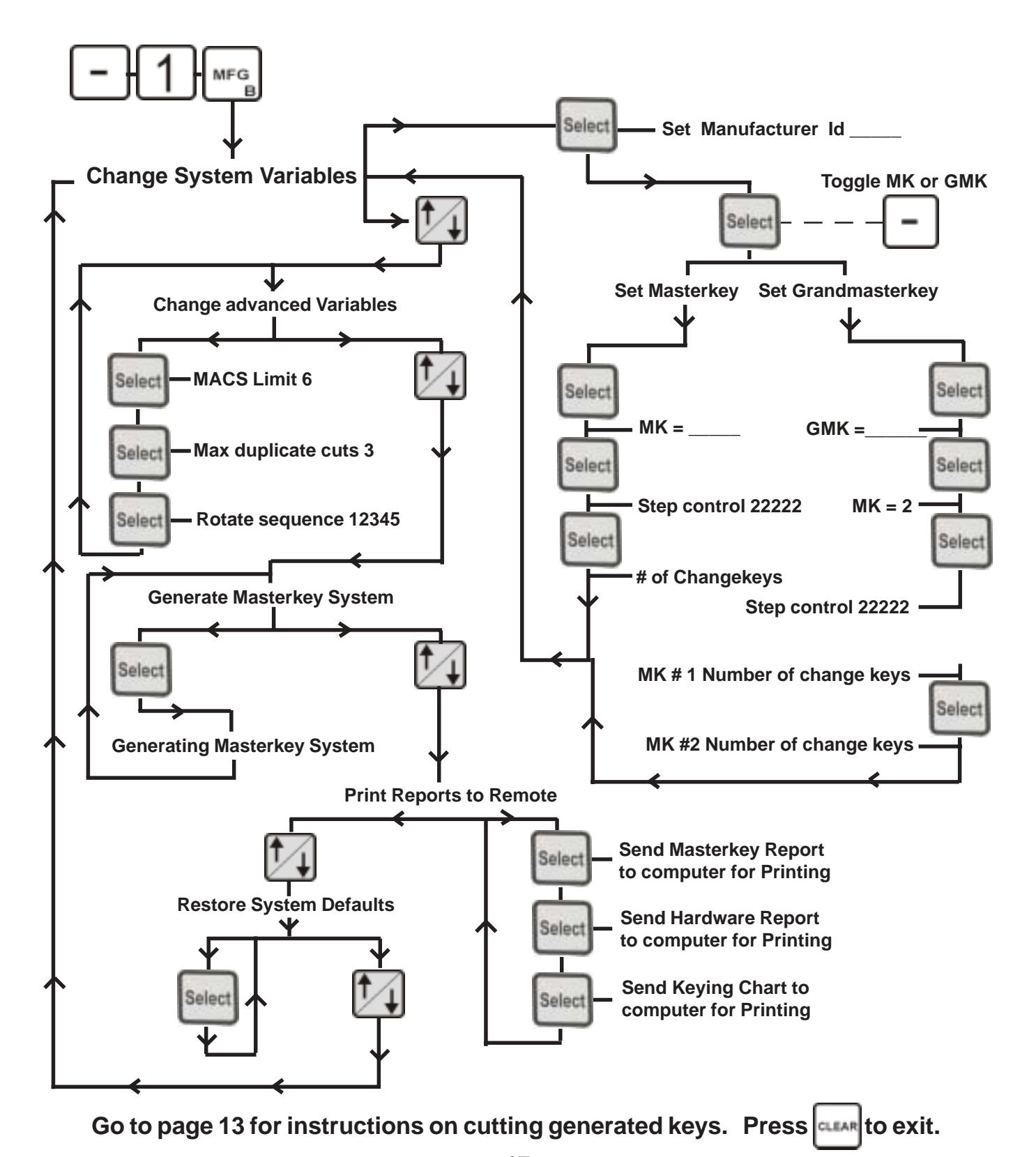
CREATING A 950C MASTER KEYING CHART

Need more help?
Our technical support team is committed to helping you.
Email Us:
techsupport@intralocktools.com
or call
toll-free at: 1-888-264-6627