INSTRUCTIONS FOR 8700,12-8700,HC-8700,HC4-8700
Open the original PDF document
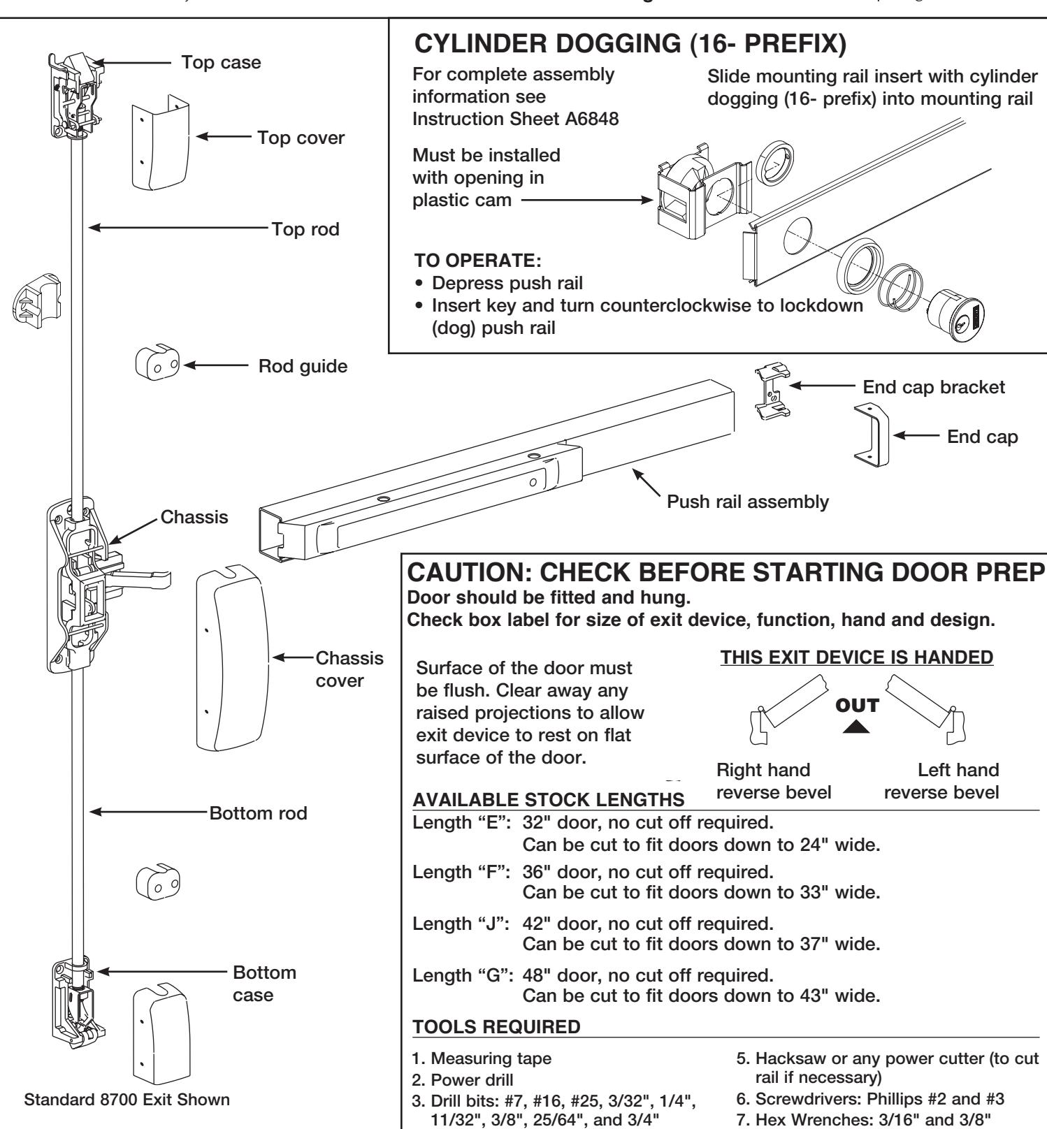
View PDFINSTALLATION INSTRUCTIONS 8700, 12-8700, HC8700 & HC4-8700 SURFACE VERTICAL ROD EXIT DEVICE
U.S. Patent No. 268,003 Canadian Patent No. RD 1981
FOR ASSISTANCE, CONTACT SARGENT AT 800-727-5477 or www.sargentlock.com
4. Taps: #10-24, #12-24, 1/4"-20 and
7/16"-20
Copyright © 2009-2011, Sargent Manufacturing Company, an ASSA ABLOY Group company. All rights reserved. Reproduction in whole or in part without the express written permission of Sargent Manufacturing Company is prohibited.
8. Level
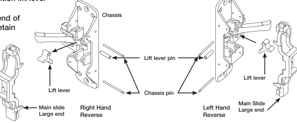
All 8700 series exit devices are handed except the 8710, which is field reversible. The 8710 is shipped as LHR unless ordered as RHR.
TO CHANGE HAND OF 8710 EXIT DEVICE:
- 1. Remove both chassis pins and main slide.
- 2. Remove lift lever pin and lift lever.
3. Rotate chassis 180° and reposition lift lever and lift lever pin as shown.
4. Position main slide with large end of main slide at the bottom and retain with chassis pins.
FIRST
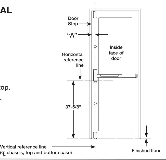
MARK VERTICAL AND HORIZONTAL REFERENCE LINES ON DOOR
WITH DOOR CLOSED:
-
1. Determine dimension "A" to locate vertical reference line. If door stile is 4-1/2" wide or wider, "A" is 2-3/4".
- If door stile is less than 4-1/2", "A" is 1/2 the exposed width of the door stile when the door is closed against the stop.
- 2. Standard rail centerline height is 41" above the finished floor. Horizontal reference line is 37-5/8" standard. (Location of lower chassis mounting holes)
SECOND
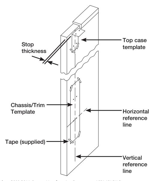
PREPARE DOOR
WITH DOOR CLOSED:
- 1. Tape template for Chassis/Trim on inside of door, along vertical and horizontal reference lines.
- 2. Fold top case template and tape on inside of door along vertical reference lines.
- 3. Spot and drill all holes from inside of door.
- 4. Mortise pockets for outside trim, if required. See trim installation instructions supplied with trim for details.
NOTE: Any holes drilled from the outside need pilot holes drilled from the inside to ensure good alignment.
NOTE: For electrical trim applications, ensure access to a raceway from the trim to the electric hinge or armored door loop.
Copyright © 2009-2011, Sargent Manufacturing Company, an ASSA ABLOY Group company. All rights reserved. Reproduction in whole or in part without the express written permission of Sargent Manufacturing Company is prohibited.
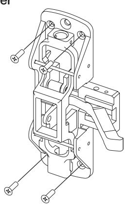
THIRD APPLY CENTER CHASSIS AND TRIM
700 SERIES ET TRIM:
1. Secure chassis to door with (4) #10 flat head screws using corner mounting holes.
NOTE: Electrical functions – see instruction sheet A6374 for wire connections.
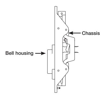
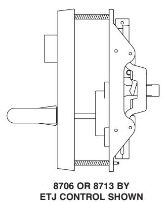
- 2. Position ET trim on door, align spindle with bell housing.
- 3. Through-bolt chassis to ET trim with (2) 1/4-20 flat head screws.
NOTE: Thumb Trim is not available for HC8700 Series Exit Devices
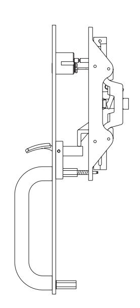
800 SERIES THUMB PIECE TRIM:
Determining rim cylinder tail length
FOR FLL, FLW, MAL, STS OR PTB TRIM:
- 1. Position trim on door (except STS).
- 2. Insert rim cylinder through trim plate (or cylinder collar for STS trim).
- 3. Mark cylinder tail at 5/16" beyond inside door surface.
- 4. Remove cylinder and trim from door and cut tail piece as marked.
5/16" STS TRIM SHOWN FLL TRIM SHOWN
8762 OR 8763 BY FLW SHOWN
APPLY CHASSIS AND TRIM:
- 1. Hold trim plate to door.
- 2. Insert cylinder and secure using supplied back plate.
- 3. Position cylinder hub with in the chassis to correct position for desired function (see drawings).
- 4. Position chassis on door, align cylinder tail with hub and secure chassis to door with (4) #10 flat head screws using the corner mounting holes.
- 5. Through-bolt chassis to trim with 1/4-20 flat head screws and to door with cup washer and 1/4-20 flat head screw.
NOTE:
STS, FLL, FLW and MAL thru-bolt to chassis with (1) 1/4-20 flat head screw.
PTB trim through-bolts to chassis with (2) 1/4-20 flat head screws.
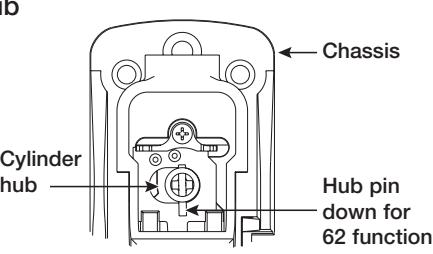
For 8762 long end of pin faces down. Cylinder turns 180° in both directions.
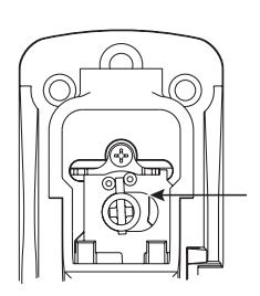
For 8763 long end of pin faces up. Cylinder turns 360° to the left or right.
APPLY RAIL ASSEMBLY
Check box label.
The following prefixes are provided "factory cut" to size: AL-, 56-, 57-, 58- and 59-.
If cutting is required, continue with step "A".
If cutting is not required, proceed to step "B".
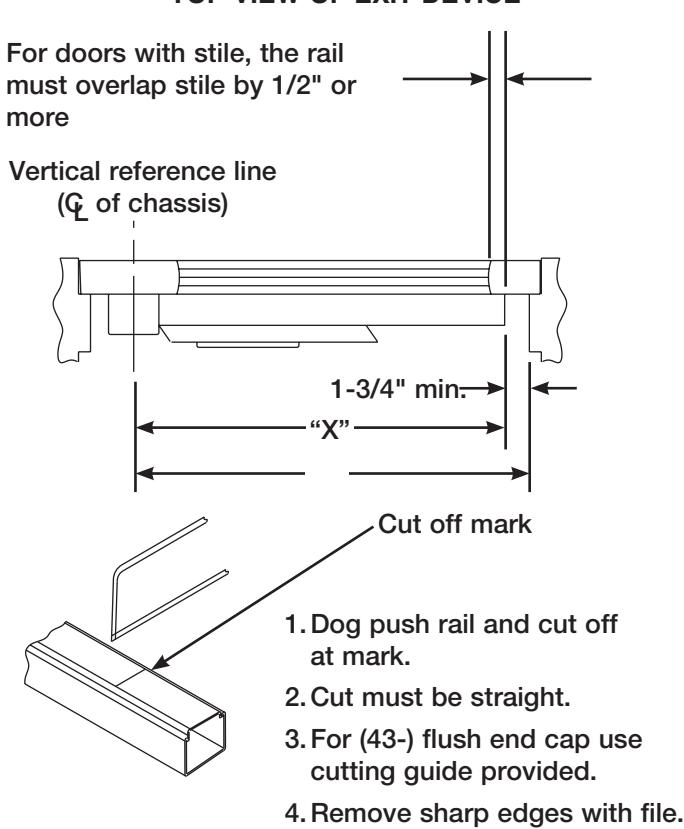
A Determine rail length dimension "X" by subtracting 1-3/4" from dimension "Y".
TOP VIEW OF EXIT DEVICE
B
- 1.Slide rail assembly over lift arm and onto chassis.
- 2.Attach rail assembly to chassis with two (2) #8-32 truss head machine screws.
NOTE: DO NOT tighten screws.
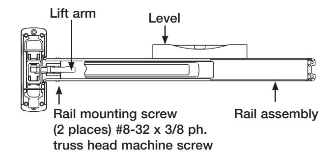
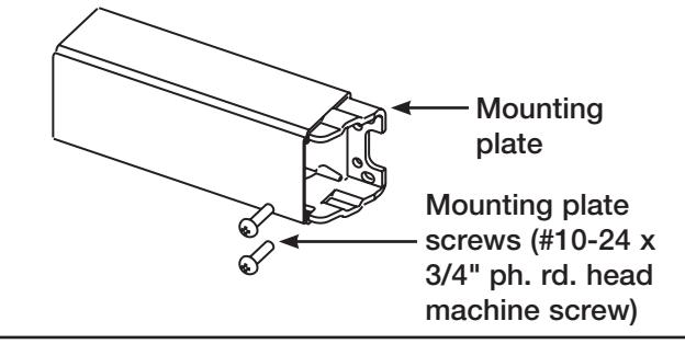
- 3. Level rail and position mounting plate tight against rail and attach to door with two (2) #10 round head screws.
- 4.Tighten all screws securely.
FIFTH MOUNT TOP CASE
- 1.Verify rail is not dogged.
- 2.Screw rod into top case until finger tight.
- 3.Slide top rod into main slide do not pin in place.
- 4.Attach top case as located in second step.
Through-bolts required and supplied for fire rated top cases on wood doors.
- 5.Unscrew top rod until the center hole is aligned with the hole in the main slide.
- 6.Insert rod adjustment pin.
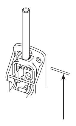
Rod adjustment pin
SIXTH
MOUNT BOTTOM CASE
SARGENT
ASSA ABLOY
- 1. Verify rail is not dogged.
- 2. Screw rod into bottom case until finger tight.
- 3. Slide bottom rod into main slide.
- 4. Insert adjustment pin into middle hole.
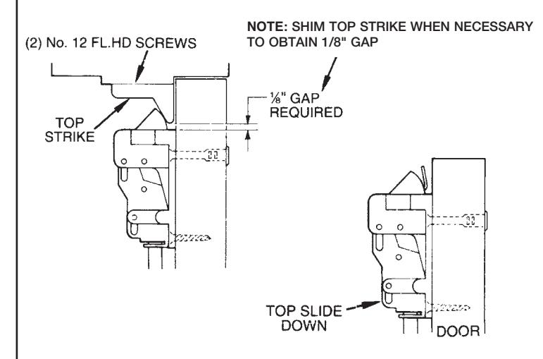
- Position bottom case on door, centered on vertical reference line. Raise or lower to achieve gap indicated for strike application (see drawings below).
- 6. Drill and tap mounting holes.
- 7. Mount bottom case. Tighten fasteners securely.
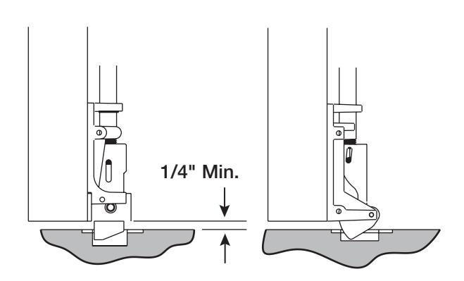
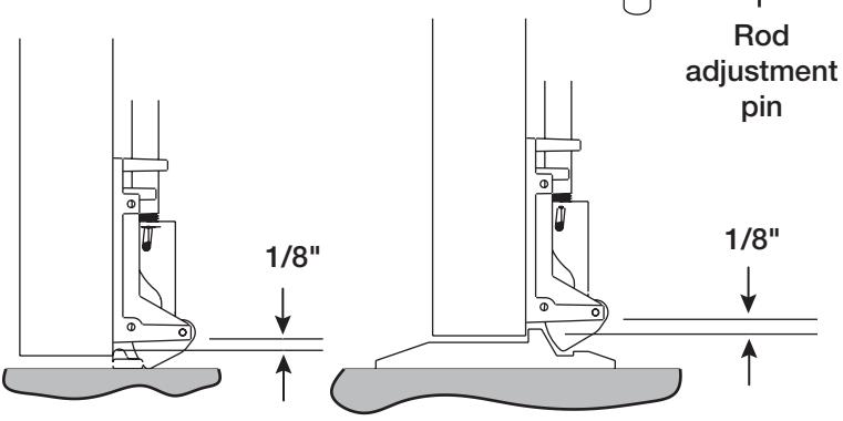
MORTISE APPLIED STRIKES
SURFACE APPLIED STRIKES
LATCHTRACKTHRESHOLDS(BY OTHERS)
SEVENTH
ATTACH STRIKES
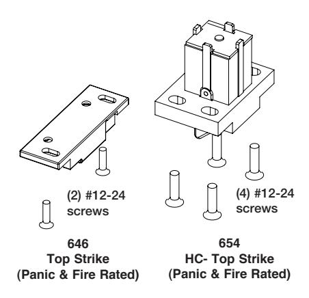
TOP STRIKES
Mount top strike in position.
Tighten screws securely.
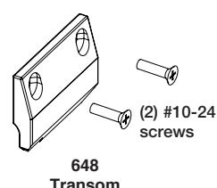
Transom Panel Strike
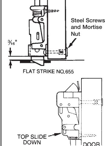
ATTACH TOP CASE
Note: Use two (2) No. 10 steel screws and mortise nuts (when provided) in the position illustrated in the top case. Steel mortise nuts are twin knurled for identification.
SEVENTH ATTACH STRIKES (Continued)
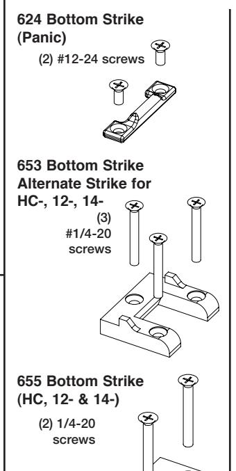
BOTTOM STRIKES
For thresholds with integral strikes, skip to next step.
For surface applied strikes 624 or 653:
WITH DOOR CLOSED:
- 1. Transfer vertical centerline to floor or threshold and mark.
- 2.Engage bottom strike with latchbolt and center on line marked.
- 3.Mark mounting holes.
- 4.Drill holes for required fasteners.
- 5.Mount strike with fasteners provided.
- 6.Tighten screws securely.
For mortised strikes: 636 or 655
Follow steps above. Mark mounting holes and outline of strike.
EIGHTH ADJUST TOP & BOTTOM RODS
- 1. Fine adjustment is made by turning rod into top and bottom case to shorten or out of top and bottom case to lengthen.
- 2. Rough adjustment is made by changing hole used for adjustment pin.
- 3. Top Rod Adjustments: Push on door as you push on the rail assembly. As soon as the door opens, release rail, the top bolt should be in the hold back position. If not, extend top bolt. Note: the top bolt must go into hold back position prior to the door opening.
ATTACH BOTTOM STRIKES & CASE
Note: Use two (2) No. 10 steel screws and mortise nuts (when provided) in the position illustrated in the bottom chase. Steel mortise nuts are twin knurled for identification.
4. Bottom Bolt Adjustments: Extend bottom bolt for maximum engagement with the bottom strike. When the top bolt is in, hold back, it also holds the bottom bolt in the retracted position. Always verify that when the bottom bolt is in the retracted position, that the bolt clears the finish floor by at least 1/8" through the swing of the door.
Be sure that both top and bottom latch bolts are adjusted for maximum engagement
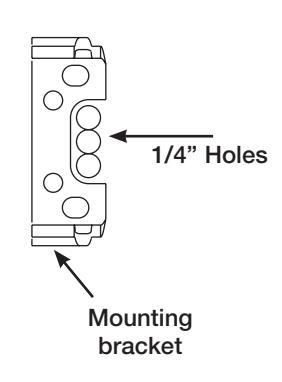
NINTH
ELECTRICAL FUNCTION PREFIXES
To access wire channel in door, drill three (3), 1/4" holes in "U" shaped cutout of mounting bracket.
59- Prefix
Connect switch cable to cable coming from the front of the rail.
Refer to instruction book A7690 for additional wire connections and operating instructions.
AL- Prefix
There are no external wire connections unless used with 546 wiring harness.
Refer to instruction book A7224 for operating instructions.
55- Prefix
Refer to instruction sheet A6808 for wire connections.
56- Prefix
Refer to instruction sheet A6876 for wire connections.
57- Prefix
Refer to instruction sheet A6810 for wire connections and operating instructions.
58- Prefix
Refer to instruction sheet A6835 for wire connections.
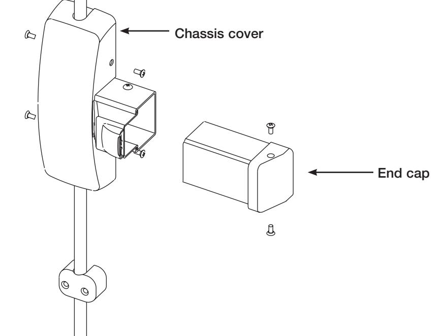
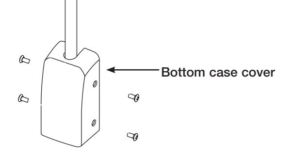
TENTH
INSTALL GUIDES, COVERS AND END CAP

- 3. Install end cap as shown.
- 4. Install top and bottom rod guides at center of rod. Rod must float freely in guide without rubbing.
- 5. For doors over 96": Install two (2) top rod guides equally spaced between the top case and chassis cover. Rod must float freely in guides.
Top case cover Rod guide
7