INSTALLATION INSTRUCTIONS IP100SGK-EM ELECTRIC LATCH RETRACTION DEVICE KIT SARGENT MODELS 8600, 8700 & 8800
Open the original PDF document
View PDF

801 Avenida Acaso, Camarillo, Ca. 93012 • (805) 494-0622 • www.sdcsecurity.com • E-mail: service@sdcsecurity.com
INSTALLATION INSTRUCTIONS IP100SGK-EM ELECTRIC LATCH RETRACTION DEVICE KIT SARGENT MODELS: 8600, 8700 & 8800
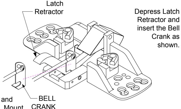
Remove the Head Assembly from the device. Carefully run the Cable inside the rail over the hinge brackets. Attach the Bell Crank as shown. Reinstall the Head Assembly to the device. Remove access cover and attach the ELR assembly to the device with the supplied screw.
Run the cable through the ELR Clevis Block and Cable Sleeve. Install the device to the door. Mount C the ELR assembly in the device by positioning the assembly close to the edge of the rail. Use the mounting tab from the exit device to secure the ELR to the base. Once the assembly is secure then use a 7/64 drill bit to drill out the inserts and use the supplied screws to fasten kit to the device and door.
CLEVIS BLOCK Carefully run the Cable inside the rail over the hinge brackets.
Attach the ELR to the device with the supplied screws.
CABLE - SLEEVE
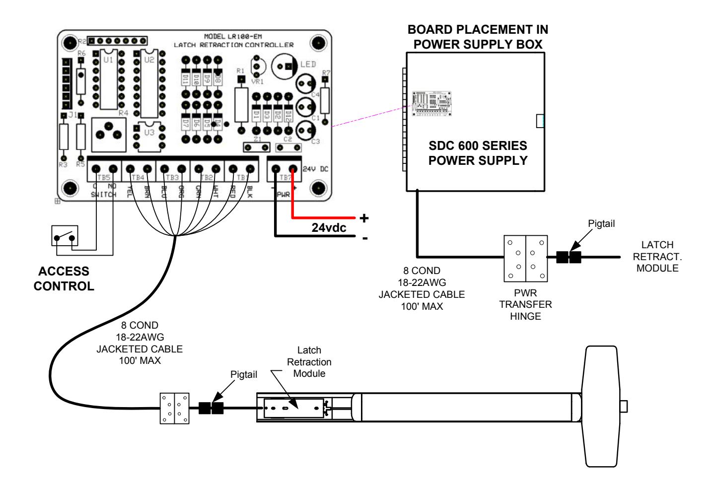
ELECTRICAL DATA 12VDC @ 700/200mA RED (+) BLK (-) PATENT #8,851,530
Energize the ELR assembly, then pull the cable so that it retracts the latch far enough to clear the strike. Hold the cable in position and secure the set screw firmly on the clevis block, so that the Cable Sleeve secures the cable in block. Test operation and re-attach access cover (NOTE: Access Cover can NOT go back on the same way as it came off. It must be rotated 180 degrees).
Retrofit Installation Note: 42" or 48" exit devices that have been modified to fit a 36" or smaller opening, may not have the required space to fit the standard E. L. R. assembly. Always verify the distance from the end of the touchpad to the end rail, and if necessary, consult with the factory for appropriate selection.