IEI 212iLW & 242iLW Standalone Keypad Installation & Programming Manual
Open the original PDF document
View PDF212iLW & 242iLW Standalone Keypad Installation & Programming Manual
Note: This equipment is designed to be installed and serviced by security and lock industry professionals.
| Put Service Company Contact Information Here: | |
|---|---|
| Company Name: | |
| Service Number: | |
Contents
| 1. |
Features and Product Description
2 |
|
|---|---|---|
| 2. | Specifi cations 4 | |
| 3. | Keypad Tampering 5 | |
| 4. | Mounting 7 | |
| 5. | Wiring 8 | |
| 6. | Testing the Keypad 15 | |
| 7. | Programming 16 | |
| 8. | Troubleshooting 25 | |
| 9. |
Wire Harness Loopback Connections
26 |
|
| 10. Limited Warranty 27 | ||
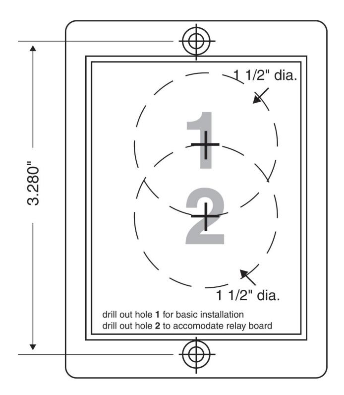
| 11. 212iLW / 242iLW Keypad Surface-mount Template 28 |

1. Features and Product Description
1.1 Keypad Features
- Flush Mount, Single Gang
- Illuminated Backlit Keys
- Keypad Programmable
- Access Control Functionality (242 model)
- Individually Control up to 4 Devices (242 model)
- Keypress Feedback via Built-In Sounder
- Bi-Color Red/Green LED Indicates Relay Status
- Yellow LED Indicates Program Mode
- 120 Users
- Panic and Duress Options
- Single Use Codes
- Lockout Users
- Passage/Toggle Codes
- 10 to 30 Volt DC Operation
- 12 to 24 Volt AC Operation
- 2 Amp Main Relay
- Remote Trigger Input (REX)
- Door Monitor Input
- 2 Year Warranty
1.1.1 Output Functionality Options (242 only)
- Four Independent Relay Outputs
- Four Independent Relay Timers
- All Relay Outputs Assignable By Code
1.1.2 Access Control Features (242 only)
- Lock Release Output With Timer
- Alarm Zone Shunt Relay
- Propped Door Alarm Relay
- Forced Door Alarm Relay
1.2 Product Description
The 242iLW keypad features the most fl exibility and options available in a self-contained unit. It has an accessory relay board that provides an additional three relays. It can perform access control functions and also its four relay outputs can be assigned independently for timed operation or to latch. The 242iLW keypad can control up to four devices, and is perfect for controlling electronic locking devices, security systems, CCTV systems, automatic operators, or machinery.
The 212iLW keypad features a single-relay output to control any device requiring an on/off switch. The output is timed or latched and operated by a user's PIN code. Additionally, the 212iLW keypad provides basic keyless entry by controlling a door locking device where security is not an issue.
The 212iLW and 242iLW style keypads are designed for both indoor and outdoor fl ush mount applications. The electronics for each keypad are conformal coated in the manufacturing process in order to provide this level of application fl exibility. In addition, each keypad uses hardened keys to assure long-term, high-quality performance. Each keypad contains illuminated clear keys that make operation in low light situations easy and accurate. Both iLW style keypads mount to any standard single-gang electrical box or directly to any wall.
NOTE: This manual covers both the 212 and 242 model. All features referring to the additional relays and outputs are available only on the 242 model.
2. Specifi cations
| Parameter | Range/Description |
|---|---|
| Voltage | 10–30 VDC, 12-24 VAC (Auto-Adjusting) |
| Current |
93 mA @ 10 VDC; 158 mA @ 30 VDC,
148 mA @ 12 VAC; 198 mA @ 24 VAC |
|
242 Model - Add 25 mA for each energized aux
relay (max = 75 mA) |
|
| Environment | For Indoor and Outdoor Use |
| Temperature Tolerance | -20° F to 130° F (-28° C to 54° C) |
| Dimensions | 5-1/8" H x 3-3/8" W x 5/8" D |
| Main Relay (Form C) | Contact Rating: 2 A @ 30 VAC/DC |
| Aux Relay (Form C) | Contact Rating: 1 A @ 24 VAC/DC |
| REX Input | Normally Open Dry Contact |
| Door Position Input | Normally Closed Dry Contact |
| LEDs | Bi-Color Red/Green; Yellow |
| Default Keypad Settings | ||
|---|---|---|
| Parameter | Default Setting | |
| Master Code | 1234 | |
| Lock Output | Relay 1 (Main relay – 212 and 242) | |
| Alarm Shunt Output | Relay 2 (242) | |
| Propped Door Output | Relay 3 (242) | |
| Forced Door Output | Relay 4 (242) | |
| Audio Alerts | Not Assigned (212 and 242) | |
| REX | Triggers Lock Output | |
| REX Operation | Always Triggers (regardless of Door Loop) | |
| Error Lockout | Enabled | |
| Error Lockout Threshold | 3 Attempts | |
| Error Lockout Duration | 10 Seconds | |
| Lock Output Time | 5 Seconds | |
| Propped Door Output Time | 30 Seconds | |
| Forced Door Output Time | 10 Seconds | |
| Visual Keypress Feedback | Enabled | |
| Audio Keypress Feedback | Enabled | |
| Auto-Entry | Disabled | |
| User Lockout | Enabled | |
3. Keypad Tampering
To prevent tampering, a tamper switch can be installed in the single gang box used for mounting the keypad. The tamper switch must activate if the keypad is removed from the box and must disconnect power from the lock. The lock must be a fail-secure device, meaning the lock remains locked when power is removed. In addition, once the tamper device is activated, it must be confi gured so that it can only be reset from within the protected area. Only a Sentrol 3012 or Sentrol 3025T tamper switch can be used. The diagrams on the next page show the suggested mounting location for each device.
3.1 Tamper Power Supply
Our access system power supply is designed specifi cally for access control applications. It features a tamper circuit with a reset button mounted on the circuit board. Using the tamper switch as detailed and connected to the power supply tamper circuit, unauthorized opening of the case or prying the unit off the wall triggers this tamper loop, thus preventing the lock from being released until the reset button is pressed.
How to Order
● Access power supply with tamper circuit in cabinet: Model PWR/TMPR12P; Order Number 0-291200
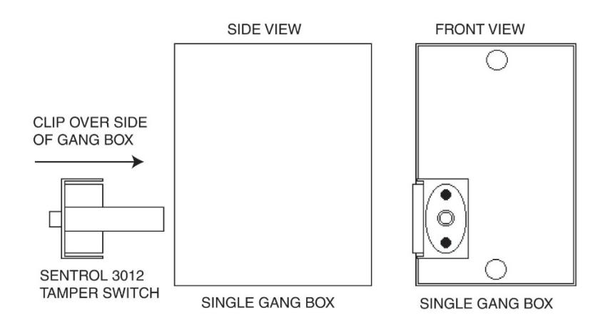
Figure 1. Mounting a Sentrol 3012 Tamper Switch
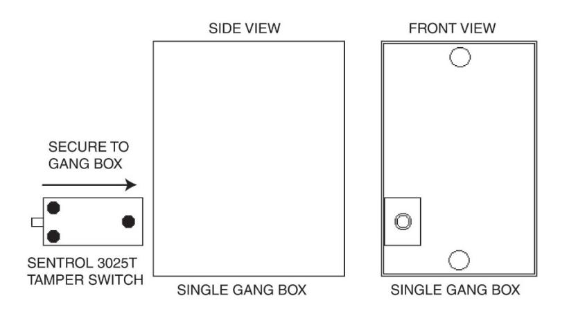
Figure 2. Mounting a Sentrol 3025T Tamper Switch
4. Mounting
The keypad is designed to be fl ush mounted using a standard single-gang electrical box. In addition, it can be fl ush mounted directly to the wall surface by cutting a hole in the wall. To properly size the mounting and wire access hole, use the installation template on the last page in this manual and on the unit's container.
Mounting height can vary depending on requirements. An appropriate range is typically between 48 and 52 inches on center off the fl oor.
For outdoor installations, use a weatherproof backbox and seal the wire entry locations with silicone and provide a drain hole. In addition, use the anti-oxidant grease pack for the wire harness connectors.
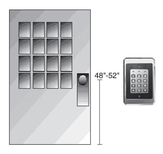
Figure 3. Keypad Mounting Height
5. Wiring
5.1 Wire Harness Confi guration
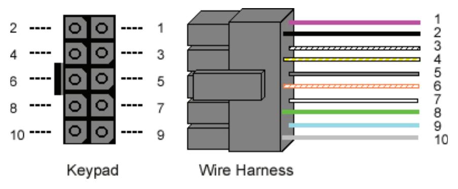
Figure 4. Keypad Connector and Wire Harness
| Pin | Wire Color | Signal Name |
|---|---|---|
| 1 | Red | V+ (Keypad Power) |
| 2 | Black | V- (Keypad Power) |
| 3 | White/Black | Not Used |
| 4 | White/Yellow | Not Used |
| 5 | Brown | Remote Trigger (REX) |
| 6 | White/Orange | Loop Common (REX and Door Loop) |
| 7 | White | Door Loop Monitor |
| 8 | Green | Main Relay – Normally Open |
| 9 | Blue | Main Relay - Common |
| 10 | Gray | Main Relay – Normally Closed |
Note: For wiring the accessory relay board, see Sections 5.6 and 5.7.
5.2 Wiring the Keypad to a Maglock (Fail-Safe)
Use the following steps to connect the keypad to a Maglock (Fail-Safe):
- 1. Connect the red wire (V+) to the blue wire (common), and then connect them to the positive on the power supply.
- 2. Connect the gray wire (normally closed) to the positive on the Maglock.
- 3. Connect the black wire (V-) to the negative on the Maglock, and then connect them to the negative on the power supply.
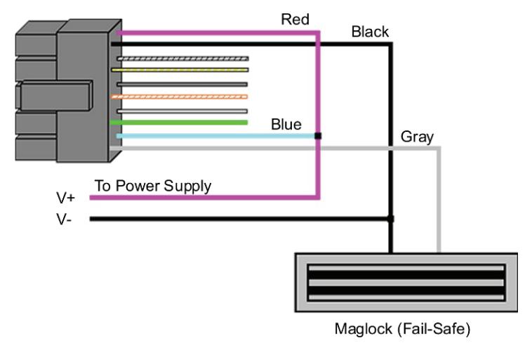
Figure 5. Wiring the Keypad to a Maglock (Fail-Safe)
5.3 Wiring the Keypad to an Electric Strike (Fail-Secure)
Use the following steps to connect the keypad to an electric strike (fail-secure) (see Figure 6 for reference):
- 1. Connect the red wire (V+) to the blue wire (common), and then connect them to the positive on the power supply.
- 2. Connect the green wire (normally open) to the positive on the strike.
- 3. Connect the black wire (V-) to the negative on the strike, and then connect them to the negative on the power supply.
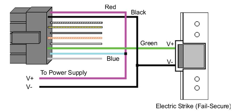
Figure 6. Wiring the Keypad to an Electric Strike (Fail-Secure)
5.4 Shunting a Normally Closed Zone
Use the following steps to use the keypad to shunt a normally closed zone:
- 1. Connect the blue wire (common) to the common connection on the door position switch.
- 2. Connect the green wire (normally open) to the normally closed connection on the door position switch.
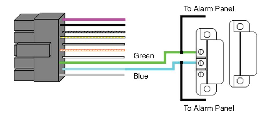
Figure 7. Shunting a Normally Closed Zone
5.5 Wiring Remote Trigger as Request to Exit (REX) Button and Door Contacts
Use the following steps to connect the keypad to a normally open REX device and normally closed door switch:
- 1. Connect the brown wire (REX Input) to the normally open connection on the REX device.
- 2. Connect the white/orange (loop common) to the common on the REX device and the common on the door switch.
- 3. Connect the white wire (door loop) to the normally closed connection on the door switch.
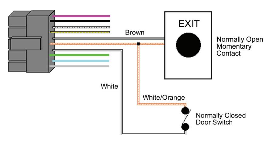
Figure 8. Wiring a REX Button and Door Contacts
NOTE: By default, the REX function operates the virtual lock output only, but you can change this using Command 49. In addition, the door loop doesn't need to be closed for the REX function to operate, by default, but setting Option 8 to 0 under Command 30, programs the REX function to operate only when the door loop is closed. This prevents the REX from re-triggering when the door is open.
5.6 Wiring an Accessory Relay Board (242 Only)
The accessory relay board contains physical outputs 2, 3, and 4 shown in the table below.
| Physical Output | Relay | Connector |
|---|---|---|
| 2 | K2 | P1 |
| 3 | K3 | P2 |
| 4 | K4 | P3 |
Use the wire harnesses supplied with the relay board to connect to the relays. The wire colors are shown in the table below.
| Wire Color | Relay Connection |
|---|---|
| Gray | Normally Closed |
| Blue | Common |
| Green | Normally Open |
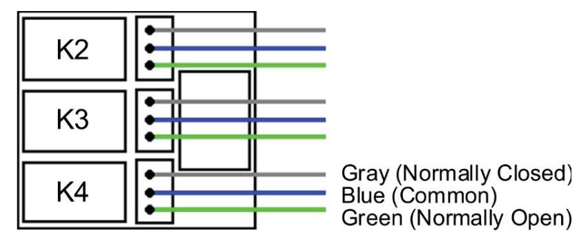
Figure 9. Wiring the Accessory Relay Board
5.7 Wiring an Integrated Access Control System Using the Accessory Relay Board
Physical outputs 2, 3, and 4 are defaulted to the alarm shunt, propped door, and forced door virtual outputs, respectively. Use the following steps to wire the alarm shunt, propped door alarm, and forced door alarm.
NOTE: You MUST wire a normally closed door switch, as shown in Figure 8 on Page 11, for these functions to work properly.
- 1. (Wiring the alarm shunt) Using P1 (K2), connect the blue wire (common) to common on the door switch. Connect the green wire (normally open) to the normally closed contact on the door switch.
- 2. (Wiring the propped door alarm) Using P2 (K3), connect the green wire (normally open) to the positive on the alarm device. Connect the blue wire (common) to the positive on the power supply. Connect the negative on the alarm device to the negative on the power supply.
- 3. (Wiring the forced door alarm) Using P3 (K4), connect the green wire (normally open) to the positive on the alarm device. Connect the blue wire (common) to the positive on the power supply. Connect the negative on the alarm device to the negative on the power supply.
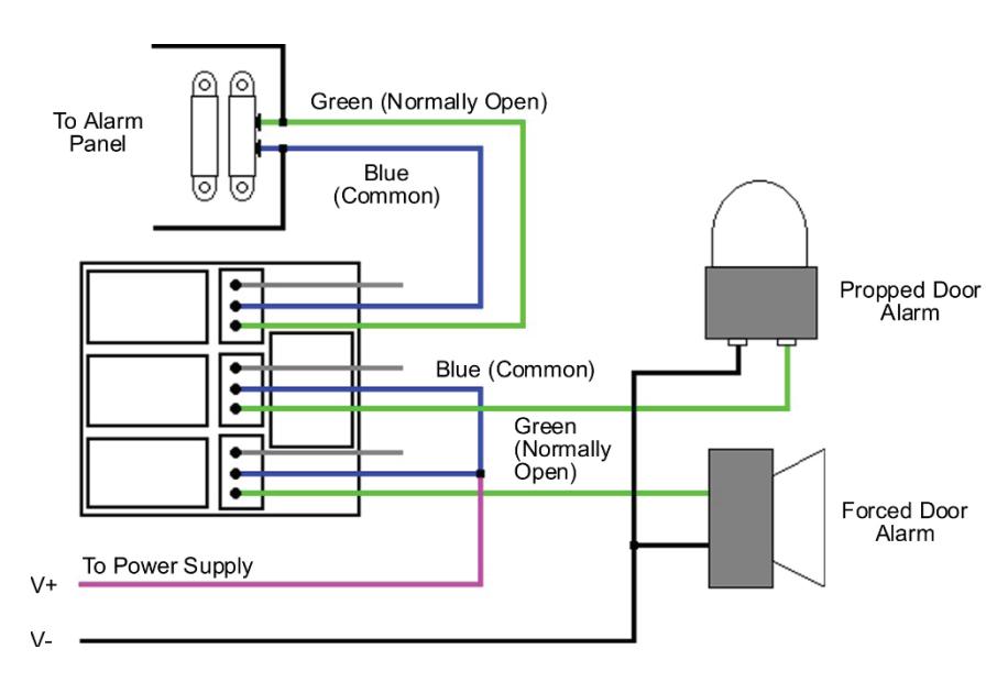
Figure 10. Wiring and Integrated Accessory Relay Board
To install the relay board, plug the relay board onto P3 on the keypad. The relays must face up towards the keypad wire harness connector P2. Use the included tie wrap to bundle all the wires together from the keypad wire harness and relay board.
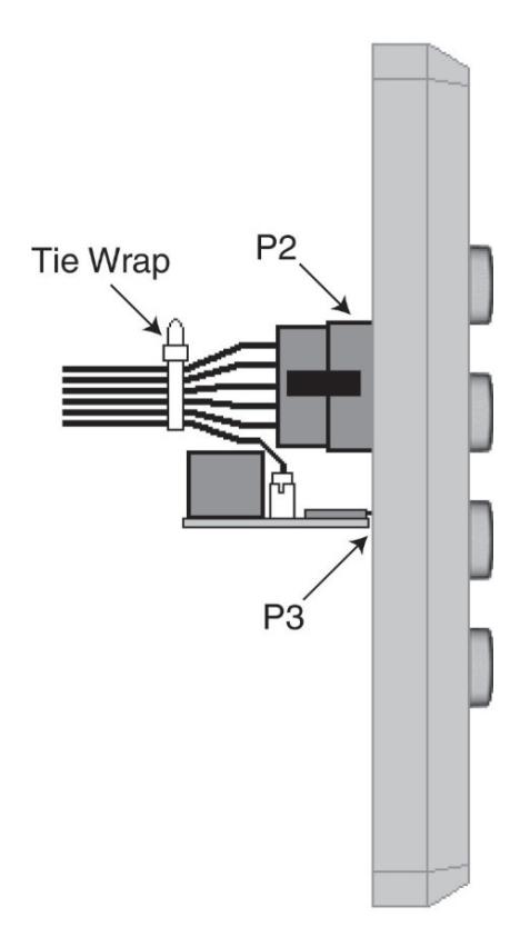
Figure 11. Plugging on Relay Board
6. Testing the Keypad
After installing the keypad, the manufacturer recommends that you perform the keypad self-test once a year, to ensure that the keypad works properly.
- 1. To perform the self-test, with the unit powered up, press the following keys on the keypad: 7890 # 123456 ✱
- If all 12 key presses are accepted, the keypad enters self-test mode.
- The LEDs alternate green, yellow, and red followed by the sounder beeping three times.
- 2. Verify that the master code works correctly. (The master code accesses program mode and activates the main relay to verify that the locking device is working.)
The default master code is 1234.
(If the default is not working, refer to Section 9.)
7. Programming
To enter program mode, press 99 # Master Code ✱. The yellow LED must then start blinking slowing (if not verify the master code is correct – refer to Section 9). The default Master Code is 1234.
NOTE: If auto-entry is enabled, the ✱ (asterisk) key is not used to enter Program mode.
To change the Master Code, enter:
1 # new Master Code ✱ new Master Code ✱ (When fi nished press the ✱ to exit program mode.)
Note: Refer to Section 7.4 for adding user codes
7.1 Programming Order
To ensure that the keypad is programmed properly in the initial installation, program the keypad in the following order:
- Step 1: Assigning Virtual Outputs to Physical Outputs
- Step 2: Programming Output Time Durations
- Step 3: Programming Users
- Step 4: Programming Keypad Options
7.2 Assigning Virtual Outputs to Physical Outputs
The keypad is equipped with both Virtual Outputs and Physical Outputs. Virtual Outputs are functions that you can assign to operate any Physical Output. Physical Outputs include the main relay, the three relays on the aux relay board, and the two audio alerts.
The 242 model has six physical outputs (four relays and two audio alerts). The 212 model has three physical outputs (a main relay and two audio alerts).
- Using Command 10, you can assign any Virtual Output to any Physical Output or disable a Physical Output.
- Each Physical Output can only have one Virtual Output assigned to it.
| Command/Action | Keys to Enter/Details |
|---|---|
|
Command 10.
Assign Virtual Outputs to Physical Outputs |
10 # virtual output # physical output # ✱ ✱ |
| Virtual Output List | Physical Output List |
|
0 – No Mapping
(Physical output unused) 1 – Lock Output* 2 – Alarm Shunt Output (242) 3 – Propped Door Output** 4 – Forced Door Output** 5 – OUT2 (242) 6 – OUT3 (242) 7 – OUT4 (242) 8 – OUT5 (242) |
1 – Relay 1 (Main Relay)
2 – Relay 2 (K2); (242 model) 3 – Relay 3 (K3); (242 model) 4 – Relay 4 (K4); (242 model) 9 – Audio Alert #1 10 – Audio Alert #2 Note: Audio alerts are described in Section 7.2.2 |
|
13 – Duress Output (242)
14 – Panic Output (242) 15 – Keypad Active Output (242) |
|
|
* The bi-color red/green LED only follows the lock output.
** On the 212 model, you can assign these to the audio alerts. |
|
|
Defaults – The keypad comes
programmed with the following default output assignments: |
The Lock Output is assigned to
Relay 1, the Alarm Shunt Output to Relay 2, the Propped Door Output to Relay 3 and the Forced Door Output to Relay 4. |
7.2.1 Virtual Outputs
| Virtual Outputs | Description/Details |
|---|---|
| Lock | This output is used for your locking device. |
| Alarm Shunt (242) |
This is used to shunt out an existing alarm panel.
It activates with the lock output and de-energizes one second after the lock time expires. |
| Propped Door |
This output activates after entering a valid user
code only if the door position switch is left open longer than the programmed propped door time. |
| Virtual Outputs | Description/Details |
|---|---|
| Forced Door |
This output activates if the door position switch is
opened without entering a valid user code. |
|
OUT2, OUT3,
OUT4, OUT5 (242) |
These four independently controlled outputs
are activated by user codes programmed to activate multiple outputs and the REX function. See programming Commands 59 and 49 in the Programming section. |
| Duress (242) |
The duress output is activated when a duress
user enters their code. See Duress User in the Programming section. |
| Panic (242) |
Panic is activated by pressing the ✱ and #
keys at the same time. This is used in case of emergency to activate an auxiliary device and should not be used to gain access. |
| Keypad Active (242) |
The Keypad Active output is activated when any
key is pressed. Do not use this output to gain access. |
7.2.2 Audio Alerts
Audio Alerts are produced by the local sounder on the keypad and can be used as a local propped door alarm or forced door alarm to free up the relays for other functions.
- Alert #1 is a constant quick beep (¼ second on and ¼ second off).
- Alert #2 is a short beep (100 ms) every two seconds.
- Alert #1 takes priority over Alert #2.
7.2.3 Programming REX Outputs (242 Model)
For wiring information, see Section 5.5.
49 # output list # 0 # ✱ ✱
Use this command to program which outputs the REX operates. 1 = LOCK, 2 = OUT2, 3 = OUT3, 4 = OUT4, and 5 = OUT5.
| Command/Action | Keys to Enter/Details | |
|---|---|---|
| Command 11. Set LOCK Time Duration | 11 # time # 0 # * * (time = 1 to 255 seconds) | |
| Command 12. Set OUT2 Time Duration | 12 # ttt # mmm # * * | To toggle, enter: 12 # 0 # 0 # * * |
| Command 13. Set OUT3 Time Duration | 13 # ttt # mmm # * * | To toggle, enter: 13 # 0 # 0 # * * |
| Command 14. Set OUT4 Time Duration | 14 # ttt # mmm # * * | To toggle, enter: 14 # 0 # 0 # * * |
| Command 15. Set OUT5 Time Duration | 15 # ttt # mmm # * * | To toggle, enter: 15 # 0 # 0 # * * |
| Options: | ||
| ttt (time units) | Number of time units to valid PIN entered (1-25) | |
| Examples: |
12 # 1 # 10 # (for 10 seconds)
(1 time unit multiplied by 10 seconds) 12 # 2 # 10 # (for 20 seconds) (2 time units multiplied by 10 seconds) |
|
| mmm (multiplier) | Number of seconds in e | |
| Examples: | 12 # 15 # 1 # (for 15 seconds) (15 time units multiplied by 1 second) 12 # 15 # 2 # (for 30 seconds) (15 time units multiplied by 2 seconds) | |
|
Command 44. Set
Propped Door Time |
44 # time # 0 # * * | |
| Options: | ||
| time | Propped Door Time - rounded down to nearest 10's of seconds; entered as 00, 10 through 990, defaults to 30 seconds; entering a time of zero disables the propped door function. | |
| Command 45. Set Forced Door Time | 45 # time # 0 # * * | |
| Options: | ||
| time | Forced Door Time - rounded down to nearest 10's of seconds; entered as 00, 10 through 990, defaults to 10 seconds; entering a time of zero latches the virtual forced door that can be cleared with any valid PIN or by entering program mode. | |
| Command/Action | Keys to Enter/Details | |
|---|---|---|
|
Command 32.
Change Keypad Parameters |
32 # parameter # value # ✱
✱ |
|
| Parameter | Value | |
| 0 – Duress Output Duration | 1 – 255 (default = 5) | |
| 1 – Panic Output Duration | 1 – 255 (default = 5) | |
| 2 – Error Lockout Threshold | 1 – 50 (default = 3) | |
| 3 – Error Lockout Duration | 1 – 255 (default = 10 |
7.4 Programming Users
| Command/Action | Keys to Enter/Details |
|---|---|
| Master Code |
User #1 is the master code; it can access all
commands in program mode. The default code is 1234. The master code can be programmed with Command 50 or Command 60 as a standard user only. |
| Supervisor Code |
User #2, when programmed, is the supervisor
code. The supervisor can access program mode, but is limited to adding and deleting users, as well as enabling or disabling users. The supervisor code can't change, delete, or disable the master code or supervisor code itself. |
|
Add Standard User
(short version) |
user location # code ✱ code ✱ |
|
Add User with
Specifi c Unlock Time |
unlock time # user location # code ✱ code ✱
(This command is used to program a user with a specifi c unlock. This user activates the virtual lock output.) |
| Delete User |
user location # ✱
✱ |
| Command/Action | Keys to Enter/Details |
|---|---|
|
Command 60.
Add/Modify Enhanced User |
60 # user type # user location # code ✱ code ✱
(codes can be from 1 to 10 digits in length) |
|
User Types
0 – Toggle User 1 – Standard User 3 – Lockout User 5 – Single Use Code 7 – Emergency User 8 – Duress User 9 – Two-Part User Type A 10 – Two-Part User Type B |
|
| Toggle User | A toggle user latches the virtual lock output. |
| Standard User |
Activates the virtual lock output using the lock
duration programmed with Command 11. |
| Lockout User |
This user type locks out users in user locations
higher than the lockout user when the lockout user code is entered. For example, if the lockout user is programmed for user 20, any user in location 21 to 120 is locked out and their codes no longer work to gain access. A lockout is removed by entering the same lockout code. If another lockout code in another user location is entered, the lockout user location level is set to the new lockout user location. The master code and emergency users can't be locked out. The current lockout is cleared when program mode is entered. "Lockout activated" is indicated by two double beeps. "Lockout canceled" is indicated by one double beep. "Access denied due to lockout" is indicated by 1 long beep followed by 3 short beeps. "User lockout" can be enabled or disabled with Command 30. |
| Single Use Code |
This code can only be entered once to gain
access using the lock virtual output. Once used, this code is no longer active. A single use code can be verifi ed by entering 5 # code ✱. If the code is a single use code, the green LED fl ashes for ½ a second. An "invalid code" is indicated by 3 quick beeps. |
| Command/Action | Keys to Enter/Details |
|---|---|
| Emergency User | This user type is a standard user that can not be |
| locked out by a lockout user. | |
| Duress User | Entering a duress code activates the lock and |
| duress virtual outputs. This allows you to trigger | |
| another device silently, such as an alarm, and | |
|
still gain access in case of an emergency.
When the two-part user option is enabled, two |
|
| codes are required to gain access. A "Two-Part | |
| Type A" and "Two-Part Type B" user must enter | |
| their code (not necessarily in that order). After | |
| the fi rst code is entered, the LED alternates | |
| between red and green, indicating another code | |
| is required. The second code must be entered | |
| Two-Part | within 15 seconds of the fi rst code. When two |
| Users A and B | codes of the same type are entered, a type |
| mismatch is indicated by 5 beeps. When Two | |
| Part User is disabled, all Type A and B user | |
| codes are converted to standard user codes. | |
| Two-Part users activate the virtual lock output. | |
| Two-Part Users can be enabled or disabled with | |
| Command 56. | Command 30. |
| Enable/Disable User |
56 # enable/disable # user location # ✱
✱ |
| Options: | 1 = Disable |
| 0 = Enable | |
| The master code and supervisor code can't be | |
| disabled. | |
| 59 # output list # user location # code ✱ code ✱ | |
|
Use this command to operate multiple outputs
and the virtual lock output using a single code. |
|
| This is useful when you want to operate a | |
| Command 59. | separate device while unlocking the door and still |
| Program users to | use some of the access control features such |
|
operate virtual outputs
OUT2, OUT3, OUT4 |
as alarm shunt, propped door, forced door and |
| and OUT5 as well as | REX. |
| the virtual lock output. | |
|
The output list is specifi ed by entering the
output(s) you want the code to operate. |
|
| 1 = LOCK, 2 = OUT2, 3 = OUT3, 4 = OUT4, and |
7.5 Programming Keypad Options
| Command/Action | Keys to Enter/Details | |
|---|---|---|
| Command 30. | ||
| Enable/Disable | 30 # option # enable/disable # ✱ | ✱ |
| Keypad Options | ||
| Option | Disable | Enable |
| 0 – Audio Keypress Feedback | 0 = disabled | 1 = ENABLED |
| 1 – Visual Keypress Feedback | 0 = disabled | 1 = ENABLED |
| 2 – Auto Entry | 0 = DISABLED | 1 = enabled |
| 3 – Error Lockout | 0 = disabled | 1 = ENABLED |
| 4 – User Lockout | 0 = disabled | 1 = ENABLED |
| 5 – Two-Part Users | 0 = disabled | 1 = ENABLED |
| 6 – Keypad Illumination | 0 = disabled | 1 = ENABLED |
| 7 – Keypad Dimming | 0 = disabled | 1 = ENABLED |
| 8 – REX Operation | 0 = only when | 1 = ALWAYS |
| door loop closed | ||
| When auto-entry is enabled, users with codes the | ||
| same length as the master code do not have to press | ||
| the ✱ key after entering their code. If you have a code | ||
| Auto Entry | greater than the master code, you can use Auto-Entry | |
| Suspend. Just enter the # key prior to your code | ||
|
followed by the ✱ key.
Example: # 23456 ✱ if the master code is four digits. |
||
| When enabled, the keypad keeps track of the number | ||
| of consecutive invalid codes entered, including | ||
| attempts to access program mode. When the | ||
| threshold is reached, the yellow LED turns on solid | ||
| Error Lockout | and the keypad no longer responds to key presses | |
| for the programmed time duration. The count is reset | ||
| by entering a valid code, including entering program | ||
| mode. The error lockout threshold and duration is | ||
| programmed with Command 32. | ||
| Keypad Illumination | Keypad backlighting can be enabled or disabled. | |
| When enabled, the backlighting illumination level | ||
| decreases 15 seconds after the last key press. When | ||
| Keypad Dimming | disabled, the backlighting remains at full illumination | |
| at all times. | ||
| Command 40. | 40 # 00000 # 00000 # ✱ ✱ (master code, all | |
| Reset Defaults Only | keypad options and parameters) | |
| Command 46. | ||
| Erase Users and | ||
| Reset Default | 46 # 00000 # 00000 # ✱ ✱ | |
| Settings. | ||
7.6 Programming Options Chart – Quick Reference To enter program mode press 99 # master code ✱ .
| Command/Action | Keys to Enter/Details | |
|---|---|---|
| Add Standard User | user location # code ✱ code ✱ | |
| Add Standard User | ||
| with Specifi c Unlock | unlock time # user location # code ✱ code ✱ | |
| Time | ||
| Add/Modify | 60 # user type # user location # code ✱ code ✱ | |
| Enhanced User | (refer to Section 7.4 for details) | |
| Delete User | user location # ✱ ✱ | |
| Set LOCK Output | 11 # time # 0 # ✱ ✱ (1 to 255 seconds) | |
| Time Duration | ||
| Enable/Disable | 30 # option # enable/disable # ✱ ✱ | |
| Keypad Options | (refer to Section 7.5 for details) | |
| Enable/Disable User | 56 # enable/disable # user location # ✱ ✱ | |
| Assign Virtual | 10 # virtual output # physical output # ✱ ✱ | |
| Outputs to Physical | (refer to Section 7.2 for details) | |
| Outputs | ||
| Program REX | 49 # output list # 0 # ✱ ✱ | |
| Outputs | ||
| Program Users to | 59 # output list # user location # code ✱ code ✱ | |
| Operate OUT2-5 | ||
| Set OUT2 Time |
12 # ttt # mmm # ✱ ✱
(refer to page 19 for details) |
|
|
Duration
Set OUT3 Time |
||
| Duration |
13 # ttt # mmm # ✱ ✱
(refer to page 19 for details) |
|
| Set OUT4 Time | ||
| Duration |
14 # ttt # mmm # ✱ ✱
(refer to page 19 for details) |
|
| Set OUT5 Time | ||
| Duration | 15 # ttt # mmm # ✱ ✱ (refer to page 19 for details) | |
| Set Propped Door | 44 # time # 0 # ✱ ✱ (10 to 990 seconds) | |
| Time | ||
| Set Forced Door | ||
| Time | 45 # time # 0 # ✱ ✱ (10 to 990 seconds) | |
| Change Keypad | 32 # parameter # value # ✱ ✱ | |
| Parameters | (refer to page 20 for details) | |
| Reset Defaults Only | 40 # 00000 # 00000 # ✱ ✱ | |
| Erase Users and | ||
| Reset Default | 46 # 00000 # 00000 # ✱ ✱ | |
| Settings | ||
8. Troubleshooting
Refer to this section if the keypad is not operating correctly as described in this manual.
| Problem | Solution |
|---|---|
|
The LEDs are
slowly cycling from right to left and backlighting is off. |
The keypad is designed to monitor the input
voltage and this is an indication of under-voltage. The under-voltage threshold is set to 8.5 VDC, and when the voltage drops below this limit, the low voltage warning starts and backlighting is turned off. To solve, raise the voltage to between 12-24 V. |
|
The LEDs are
rapidly cycling from left to right and the keypad has lost all operation. |
The keypad is designed to monitor the input
voltage, and this is an indication of over-voltage. The over-voltage threshold is set to 36 VDC, and when the voltage rises above this limit, the over voltage warning starts and the keypad loses all operation. To solve, lower the voltage to between 12-24 V. |
|
The master code
does not work. |
Perform the programming mode loopback and
reset the master code using the programming command. |
|
No LEDs are lit on
the keypad. |
Power is not reaching the keypad. Using a
voltmeter, confi rm that there is voltage at the keypad on the red and black wires. If there is no voltage at the keypad, verify that there is voltage at the power supply. If there is no voltage at the power supply, call the manufacturer of the power supply. If there is voltage at the power supply but not at the keypad, verify there is no break in the wires, then check continuity in the whole length of the wire run. To verify that the keypad is working, you can power the keypad with a 12-Volt Battery. |
DEALERS/INSTALLERS ONLY! End users must contact the dealer/installer for support. If the keypad still does not work after troubleshooting, please call the Technical Services department at 1-800-421-1587.
9. Wire Harness Loopback Connections
If the Master Code is either not working or forgotten, power down the system, connect the wire harness as shown in Figure 12 below, and then power the system up again. The unit should now be in program mode. Next, change your Master Code using the programming command and power down the system and restore the wire harness to its original confi guration and power the system back up.

Figure 12. Program Mode Loopback
10. Limited Warranty
This Nortek Security & Control product is warranted against defects in material and workmanship for twenty four (24) months. This warranty extends only to wholesale customers who buy direct from Nortek Security & Control or through Nortek Security & Control's normal distribution channels. Nortek Security & Control does not warrant this product to consumers. Consumers should inquire from their selling dealer as to the nature of the dealer's warranty, if any. There are no obligations or liabilities on the part of Nortek Security & Control LLC for consequential damages arising out of or in connection with use or performance of this product or other indirect damages with respect to loss of property, revenue, or profi t, or cost of removal, installation, or reinstallation. All implied warranties, including implied warranties for merchantability and implied warranties for fi tness, are valid only until the warranty expires. This Nortek Security & Control LLC Warranty is in lieu of all other warranties express or implied.
All products returned for warranty service require a Return Authorization Number (RA#). Contact Returns at 1-855-546-3351 for an RA# and other important details.
11. 212iLW / 242iLW Keypad Surface-mount Template