IDC 10TD900TR Transmitter Specification Sheet
Open the original PDF document
View PDF

Ideal For Harsh Environment
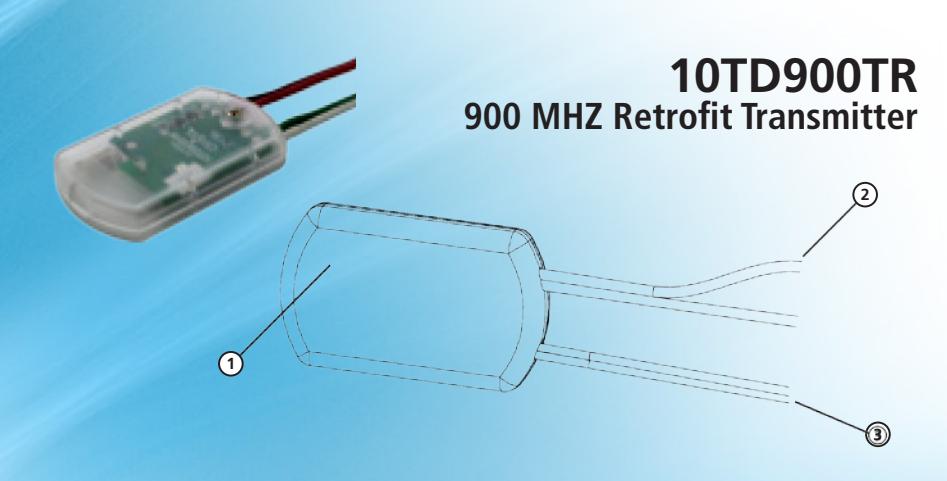
- 1. 900 MHz Wireless Transmitter
- 2. White and Green Activation Wires
- 3. Red and Black Power Wires
Precautions
- Shut off all power going to header before attempting any wiring procedures.
- Maintain a clean and safe environment when working in public areas.
- Constantly be aware of pedestrian traffic around the door area.
- Always stop pedestrian traffic through the doorway when performing tests that may result in unexpected reactions by the door.
- ESD (electrostatic discharge): Circuit boards are vulnerable to damage by electrostatic discharge. Before handling any board, ensure you dissipate your body's ESD charge.
- Always check placement of all wiring before powering up to ensure that moving door parts will not catch any wires and cause damage to equipment.
- Ensure compliance with all applicable safety standards (i.e. ANSI A156.10) upon completion of installation.
- DO NOT attempt any internal repair of the components. All repairs and/or component replacements must be performed by BEA, Inc. Unauthorized disassembly or repair:
- 1. May jeopardize personal safety and may expose one to the risk of electrical shock.
- 2. May adversely affect the safe and reliable performance of the product resulting in a voided warranty.
In most applications for existing hard-wired touch push plates, only two (2) wires are installed which run within the wall from the push plate to the door control for activation.
The 900 MHz Touchless Retrofit Transmitter allows an existing, hard-wired, touch, push plate to be retrofitted with a new touchless plate that requires four (4) wires (2 wires for power and 2 wires for activation) without running additional wires.
This is achieved by use of a powered wireless transmitter and wireless receiver.
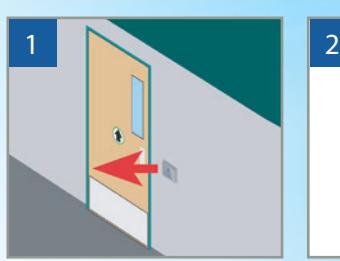
Remove existing touch push plate and disconnect the two (2) existing in-wall wires from the push plate and door control activation.
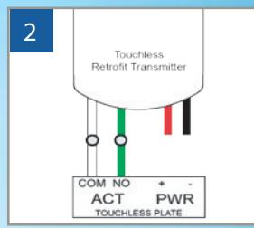
Connect the green and white wires to the new touchless plate activation output.
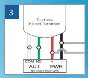
Parallel the red and black wires with the two (2) existing in-wall wires and connect them to the new touchless plate power input.
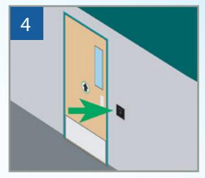
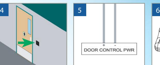
Mount new touchless plate. Connect the two (2) existing inwall wires to the power source in the door control header.
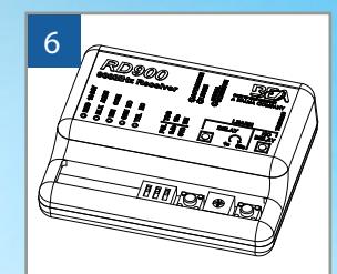
Install the 900 MHz wireless receiver in the header (sold separately).
| Technical Specifications | |
|---|---|
| Power | 12 – 24 VAC/VDC ±10% |
| Transmitter Frequency | 908 – 918 MHz (frequency hopping) |
| Emitted radio power | -25 dBm |
| Power consumption | 22 mA |
| Temperature range | 14 – 131 °F (-10 – 55 °C) |
| LEDs | Red (activation) |
| Dimensions: | 1.72" (L) x 1.06" (W) x 0.32" (T) |
| Material | ABS Plastic |
| Certification | FCC, IC |
West: 800-544-4422 • East: 800-225-6737