I-ED00793-Rev4_(Rev 2 product only)
Open the original PDF document
View PDF

DEVICES COVERED IN THIS DOCUMENT:
4700S Panic Surface Vertical Rod Device 4700L Panic Less Bottom Rod (LBR) Device 4700SF Fire Exit Surface Vertical Rod Device
#7 drill, ¼"-20 tap #16 drill, #12-24 tap
to see if your application requires the use of sleeve nuts and bolts.
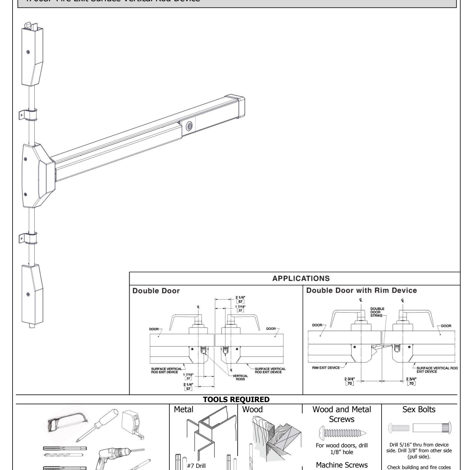
1/8" Drill
#16 Drill #12-24 Tap
¼"-20 Tap

Rev 4, Rev Date: 05/31/2018 Page 2 of 8

The exit device comes in two models, one sized for a 36" door width and one sized for a 48" door width. For other door widths, cut exit device to appropriate length. Recommended overall length of the exit device is equal to door width minus 4 inches. Cut with hack saw or metal cutting saw blade. Deburr edges.
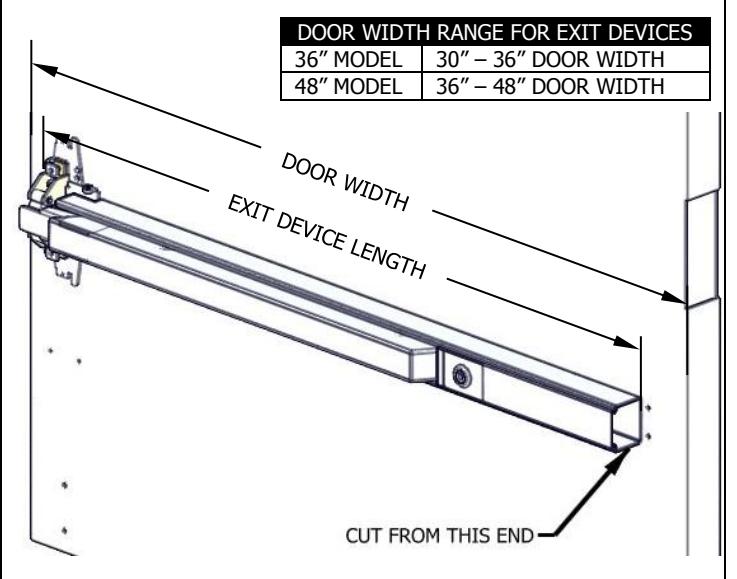
RECOMMENDED EXIT DEVICE LENGTH=DOOR WIDTH – 4"
3. INSTALL EXIT DEVICE 4. INSTALL END CAP
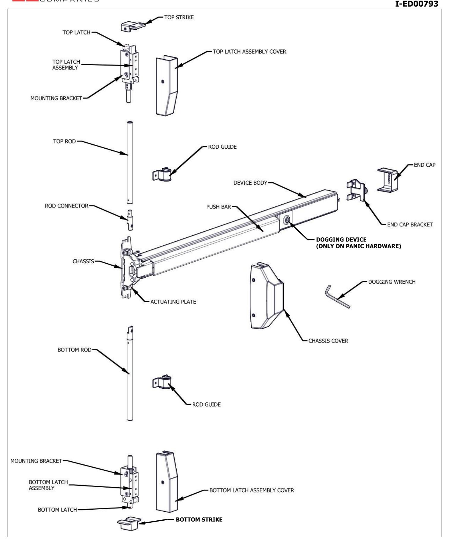
Remove head cover from exit device chassis. Mount exit device using the 2 mounting holes indicated on template.
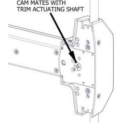
If using trim, be sure to line up trim actuating shaft (tailpiece) with cam located on back of exit device chassis.


Metal door, Sex Bolt, or Trim: ¼"-20 machine screws (2) Wood door: #12 wood screws (2)
1. CUT EXIT DEVICE TO LENGTH 2. MARK DOOR AND DRILL MOUNTING HOLES
Measure horizontal center line of exit device at 40" from finished floor. Apply template to door using centerline and edge of door. Mark and drill holes as shown on template. Be sure the vertical centerline for the exit device mounting holes is 2 ¼" from the edge of the door.
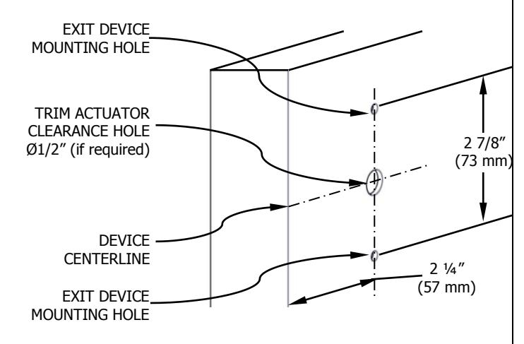
- For metal doors, drill and tap for ¼"-20 machine screws
- For wood doors, pre-drill 1/8" holes
- If mounting trim, drill 5/16" clearance holes on exit device side of door (push side) and ½" holes on pull side. Trim requires an additional ½" clearance hole for the trim actuating shaft.
- If using Sex Bolts, drill 5/16" clearance holes on exit device side of door (push side) & 3/8" on pull side
Remove end cap from end cap bracket. Mark hole locations by either using template or holding end cap bracket up against door. Be sure exit device is level before inserting end cap bracket lip into end of device body. Mark and drill / tap holes. Install end cap bracket and end cap.
- For metal doors, drill and tap for ¼"-20 machine screws
- For wood doors, pre-drill 1/8" holes
- For Sex Bolts, drill 5/16" clearance holes on exit device side (push side) and 3/8" on pull side.
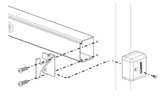
Screws:
Metal door or Sex Bolt: ¼"-20 machine screws (2)
Wood door: #12 wood screws (2)

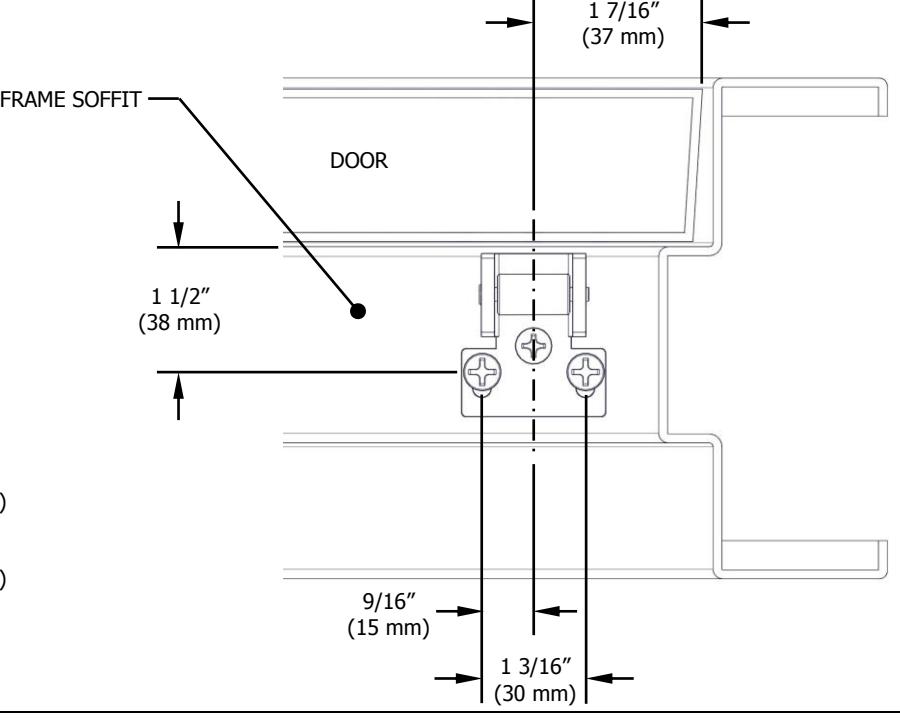
5. INSTALL BOTTOM LATCH MOUNTING BRACKET (Skip this step if installing as LBR)
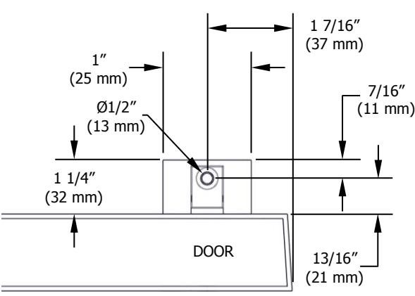
Remove bottom latch cover and mounting bracket from bottom latch assembly. Apply template to door using edge of door and either top of threshold or finished floor. Mark and drill holes as shown on template. If using bottom strike, use template to mark location for bottom strike anchor. Be sure the vertical centerline for the bottom latch mounting holes is 1 7/16" from the edge of door. Install bottom latch mounting bracket.
- For metal doors, drill and tap for 1/4"-20 machine screws
- For wood doors, pre-drill 1/8" holes
- For Sex Bolts, drill 5/16" clearance holes on exit device side (push side) and 3/8" on pull side.
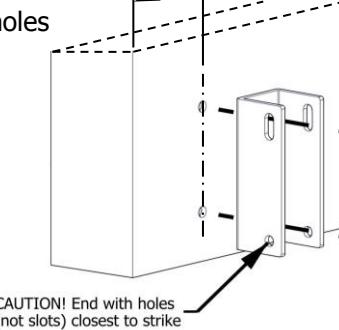
1 7/16" (37 mm)
Screws:
Metal door or Sex Bolt: 1/4"-20 machine screws (2)
Wood door: #12 wood screws (2)
6. INSTALL BOTTOM STRIKE (Skip this step if using a panic threshold or installing as LBR)
- STEP 1: Bottom strike anchor location should already be marked. If not, extend bottom latch mounting bracket centerline to finished floor or threashold
- STEP 2: Cut out hole in finished floor or threashold for bottom strike. For flush mounting, the hole depth should be 13/16" deep. For surface mounting, the hole depth should be 11/16"
- STEP 3: At bottom of strike cutout, mark and drill Ø1/2" by 7/8" deep hole for screw anchor
- STEP 4: Insert anchor and secure bottom strike to anchor
- NOTE: If required, grout around bottom strike to acquire flush and level floor. If bottom strike is being installed in a saddle threshold, a minimum 1/2" gap is required at bottom of door.
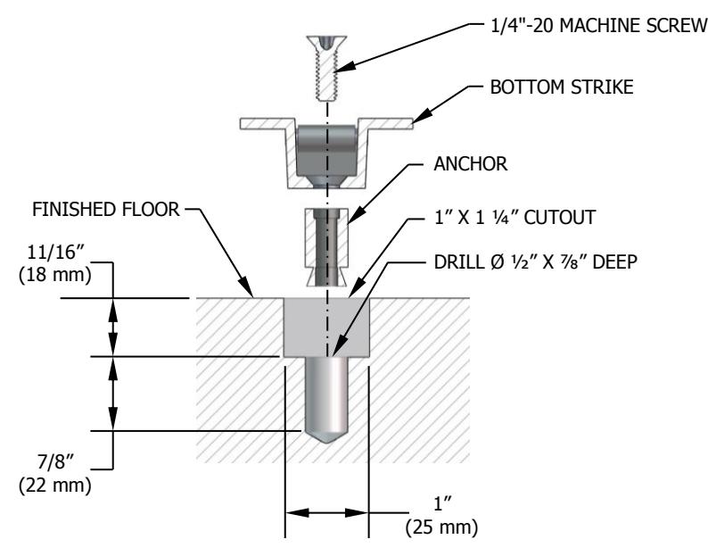
BOTTOM STRIKE INSTALLATION (SURFACE MOUNTING SHOWN)
Screws:
1/4"-20 machine screw and anchor assembly
BOTTOM STRIKE CUT-OUT (TOP VIEW)
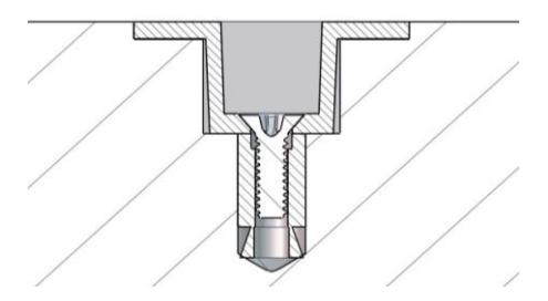
FLUSH MOUNTED BOTTOM STRIKE
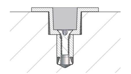
SURFACE MOUNTED BOTTOM STRIKE
Rev 4, Rev Date: 05/31/2018 Page 4 of 8

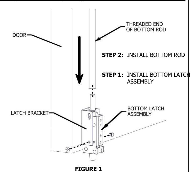
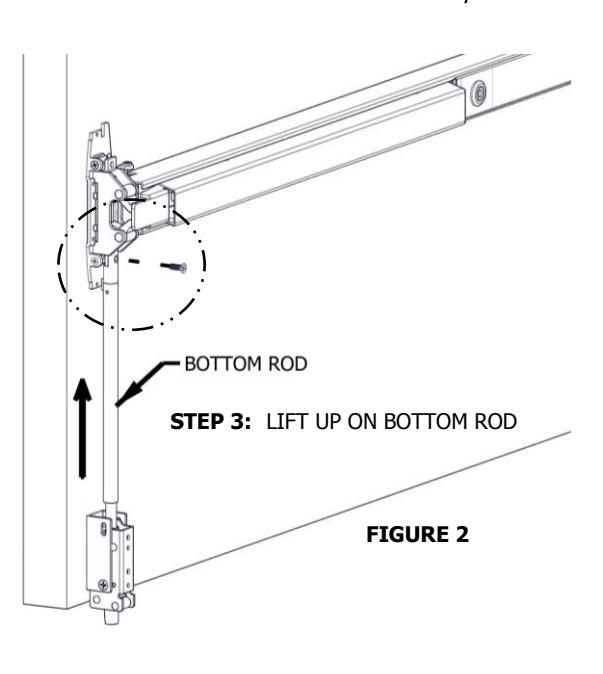
7. INSTALL BOTTOM LATCH AND ROD (Skip this step if installing LBR)
- STEP 1: Install bottom latch assembly to bottom latch bracket using provided screws and bottom two holes in bracket (see figure 1)
- STEP 2: Screw threaded end of bottom rod halfway onto bottom latch assembly.
- STEP 3: Before aligning the top end of the bottom rod with the actuating plate, lift up on the bottom rod until you feel the resistance from the bottom latch spring. At this point, stop pulling up (see figure 2).
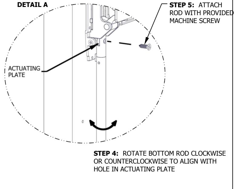
- STEP 4: Continue holding rod up while aligning the top end of the bottom rod with the actuating plate. Align by rotating rod clockwise or counterclockwise until the holes line up (see detail A).
- STEP 5: Use the provided machine screw to attach rod to actuating plate. Be sure actuating plate on the chassis is in the down position (see detail A).
- NOTE: The bottom latch assembly has a security feature. This requires the bottom rod to be adjusted as described above. Be sure there is no slack in the bottom latch. To check for slack, grab the bottom rod and pull up. If it doesn't pull the latch bolt up immediately, there is too much slack. Disconnect the top of the bottom rod, screw bottom rod further onto bottom latch assembly. Reconnect top end and check again.
CHECK INSTALLATION by pushing on exit device push bar. Make sure bottom latch is retracted when push bar is depressed. Bottom latch should clear the finished floor, strike, or threshold. Bottom latch should have 3/8" throw.
Rev 4, Rev Date: 05/31/2018 Page 5 of 8

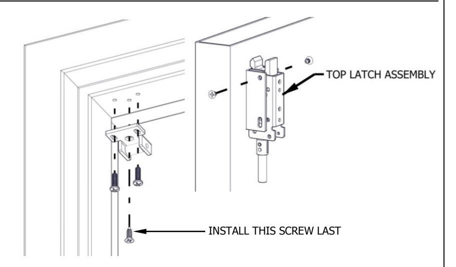
8. INSTALL TOP MOUNTING BRACKET
Remove top latch cover and mounting bracket from top latch assembly. Fold and apply template to door using edge of door and face of top stop. Mark and drill holes as shown on template for both top latch bracket and strike. Be sure the vertical centerline for the top latch mounting holes is 1 7/16" from the edge of door. Install top mounting bracket.
- For metal doors, drill and tap for 1/4"-20 machine screws
- For wood doors, pre-drill 1/8" holes
- For Sex Bolts, drill 5/16" clearance holes on exit device side (push side) and 3/8" on pull side
1 7/16" (37 mm) 1 7/8" (48 mm)
Screws :
Metal doors or Sex Bolt: 1/4"-20 machine screws (2) Wood door: #12 wood screws (2)
9. INSTALL TOP LATCH AND STRIKE
- STEP 1: Install top strike to face of stop using only the two outer slotted mounting holes.
- STEP 2: Install top latch assembly to top mounting bracket using provided screws and top two holes in bracket.
- STEP 3: Close door, check alignment of strike and top latch, adjust if required, and install screw into center hole in strike.
- For metal stop, drill and tap for #12-24 machine screws
- For wood stop, pre-drill 1/8" holes
Strike Screws :
Metal Stop:
#12-24 button head machine screws (2)
#12-24/#10 flat head combo machine/wood screw (1) Wood Stop:
#10 button head wood screws (2)
#12-24/#10 flat head combo machine/wood screw (1)
Rev 4, Rev Date: 05/31/2018 Page 6 of 8

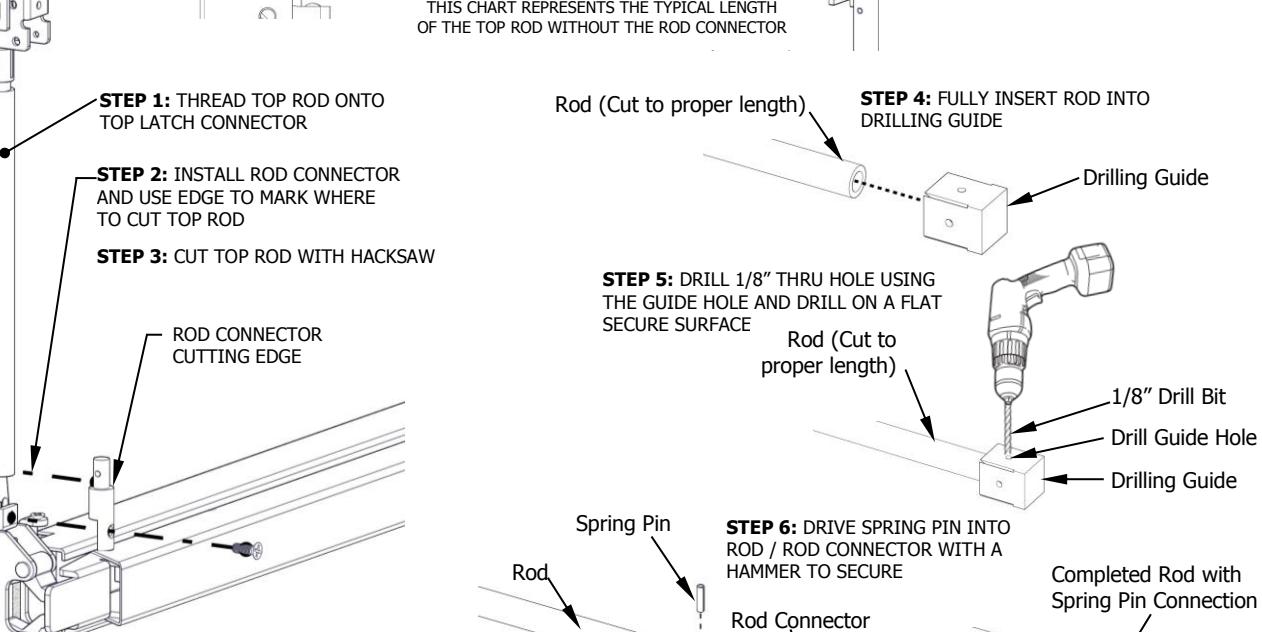
10. INSTALL TOP ROD
- STEP 1: Thread top rod half-way onto top latch threaded connector.
- STEP 2: Use the provided machine screw to attach rod connector onto actuating plate, but do not attach top rod and rod connector yet. Align the edge of rod connector next to top rod and mark a cutting line on top rod. Be sure actuating plate on the chassis is in the down position.
- STEP 3: Remove top rod and cut top rod with hack saw or metal cutting saw blade. Deburr edges.
- STEP 4: Slide newly cut rod into drilling guide until it stops. Drilling guide sets the hole location so be sure rod is fully inserted.
- STEP 5: Lay the rod with the drilling guide flat on a table. Use one of the existing 1/8" guide holes on any side of the drilling guide and drill an 1/8" hole through the rod.
-
STEP 6:
Install rod connector:
- Slide the rod connector into the newly drilled end of the rod and line up the hole in the rod connector with the hole that was just drilled into the rod.
- Use a hammer to tap the provided spring pin into the hole until it is fully seated. Check that there is a secure connection between the rod and rod connector.
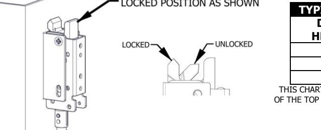
- STEP 7: Be sure the top latch is in the locked position. Thread top rod halfway onto top latch threaded connector. Fasten bottom end of top rod onto actuating plate on exit device chassis. This may require raising or lowering the top rod by threading it clockwise or counterclockwise on the top latch threaded connector.
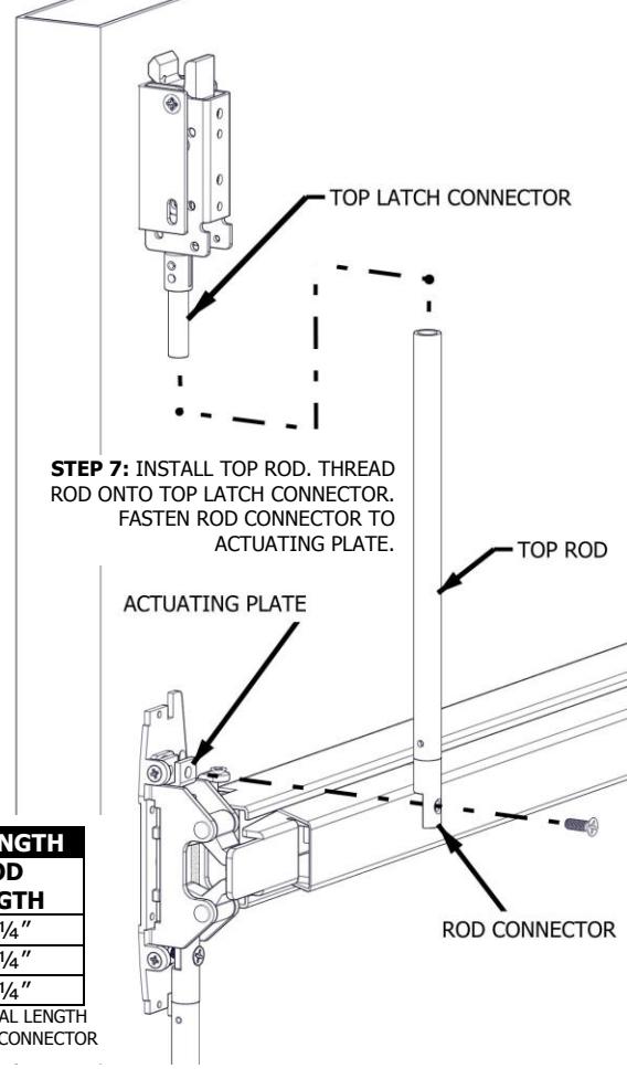
| TYPICAL TOP ROD LENGTH | |
|---|---|
| DOOR | ROD |
| HEIGHT | LENGTH |
| 6' 8" | 31 ¼" |
| 7' | 35 ¼" |
| 8' | 47 ¼" |
THIS CHART REPRESENTS THE TYPICAL LENGTH
Rev 4, Rev Date: 05/31/2018 Page 7 of 8

11. ADJUST AND TEST INSTALLATION
EXIT DEVICE OPERATION
When push bar is depressed and the door is opened, the top and bottom latch should be held retracted until door closes. When the push bar is released both latches remain in the retracted state. When the door closes and the top latch engages with the top strike, it releases the holding mechanism and allows the bottom latch to fully extend.
If the latches do not work smoothly when opening and closing the door, adjust the rod accordingly:
If the bottom latch does not clear the strike or threshold:
- Disconnect the bottom rod from the actuating plate and rotate the rod clockwise, which will raise the rod and latch bolt.
If the top latch does not clear the strike:
- Disconnect the top rod from the actuating plate and rotate the rod clockwise, which will shorten the overall distance. This will allow the top latch to completely rotate out of the way of the strike.
If the top latch will not stay in unlocked position after opening door:
- Check that the latch is not too far away from the strike. If so, add one of the included top strike shims to lower top strike.
- After adjusting the strike, readjust the top rod length to that the latch falls smoothly into the unlocked state.
Install chassis head cover and both top and bottom latch covers.
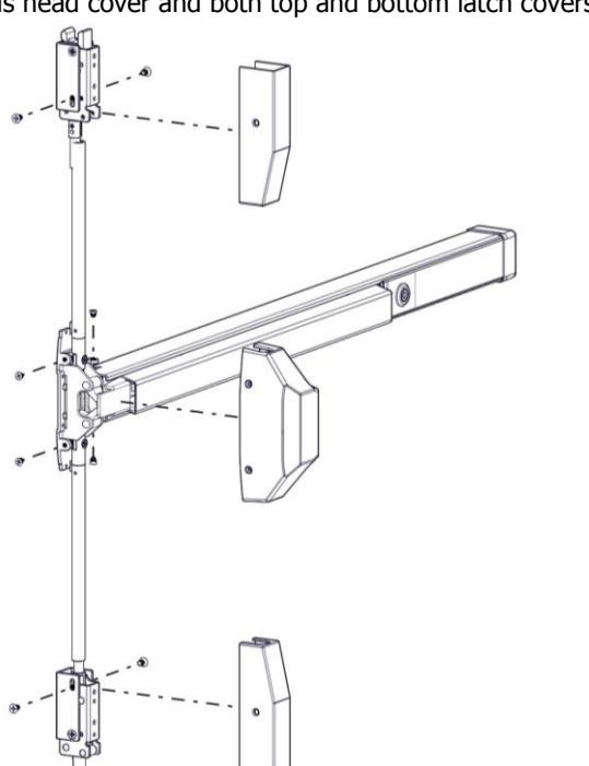
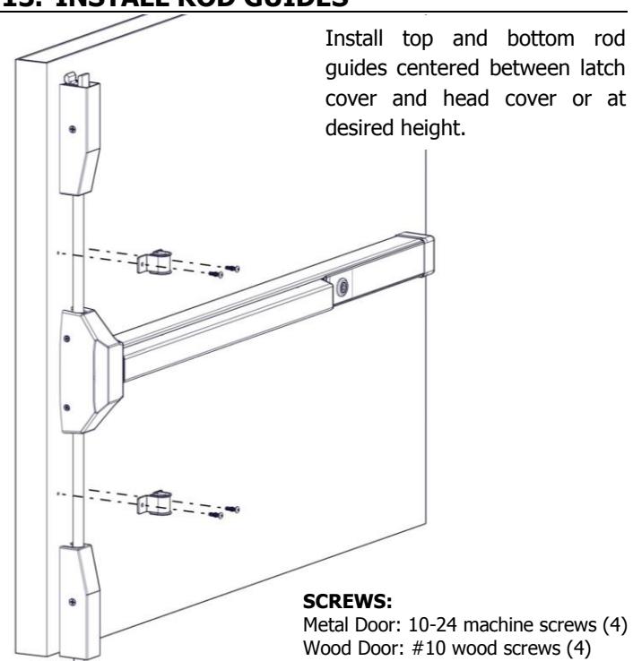
12. INSTALL COVERS 13. INSTALL ROD GUIDES
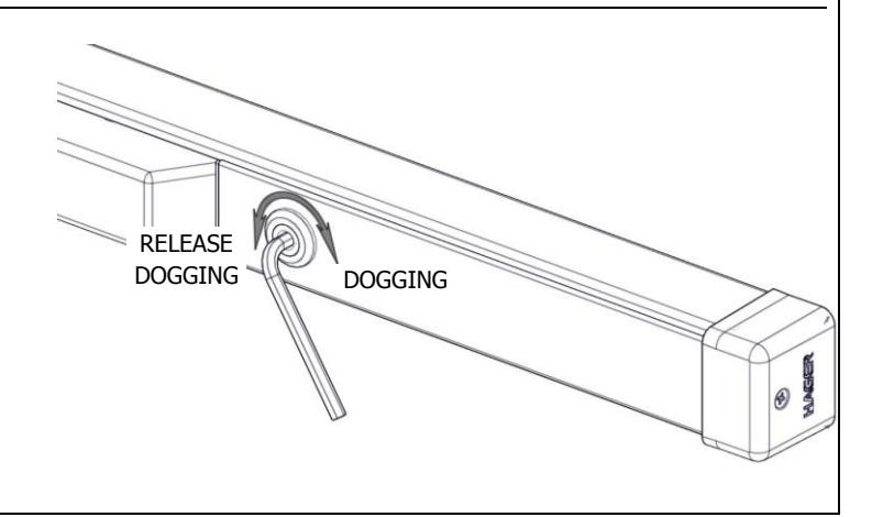
14. DOGGING DEVICE
For increasing the life of this device, dog device during high traffic periods of the day. (A dogging device is not available on fire rated models).
Dogging:
Depress push bar, then insert dogging hex wrench and turn clockwise 90°. The push bar will remain depressed and the latch will stay retracted.
Release Dogging:
Hold push bar, then insert dogging hex wrench and turn counterclockwise 90°. The push bar will return to the up position and latch will extend to secure door.
Rev 4, Rev Date: 05/31/2018 Page 8 of 8