I-EA00310-power_supply_chargers
Open the original PDF document
View PDF

2-679-1162 , 2-679-1163, 2-679-1164
Overview:
Hager power supply/chargers convert a 120VAC, 60Hz input to a 12VDC or 24VDC output.
Configuration Chart:
| Hager Model | Input Rating | Output Voltage (Current) | Maximum | |||
|---|---|---|---|---|---|---|
| Number | 115VAC 60Hz | 12VDC | 24VDC | Charge Current | Battery Fuse | |
| 2-679-1162 | 3.5A | 6A | 6A | 0.7A | N/A | |
| 2-679-1163 | 4.2A | – | 10A | 3.6A | 15A 32V | |
| 2-679-1164 | 2.6A | 10A | – | 0.7A | 15A 32V | |
Specifications:
2-679-1162 , 2-679-1163, 2-679-1164:
Input:
• See Configuration Chart pg. 1.
Output:
- For output voltage and supply current refer to Configuration Chart, pg. 1.
- Overvoltage protection.
Battery Backup:
- Built-in charger for sealed lead acid or gel type batteries.
- See Configuration Chart pg. 1. for maximum charge current.
- Automatic switch over to stand-by battery when AC fails. Transfer to stand-by battery power is instantaneous with no interruption.
Supervision:
- AC fail supervision (form "C" contacts).
- Battery fail & presence supervision (form "C" contacts).
Fuse Ratings:
• Refer to Configuration Chart pg. 1.
Visual Indicators:
- Green AC Power LED indicates 120VAC present.
- AC input and DC output LED indicators.
- BAT trouble LED indicator
Additional Features:
• Short circuit and overload protection.
Fig. 1
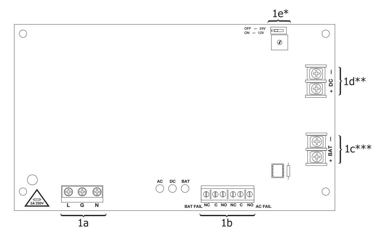
- * Output Voltage Selection DIP Switch. Not applicable for 2-679-1163 and 2-679-1164 .
- ** 2-679-1164 terminals marked [– DC +]
- *** 2-679-1163 terminals marked [– BAT +]

HS4 POWER SUPPLY/CHARGERS Installation Instructions I-EA00310
Installation Instructions: 2-679-1162 , 2-679-1163, 2-679-1164:
Wiring methods shall be in accordance with the National Electrical Code/NFPA 70/NFPA 72/ANSI, the Canadian Electrical Code and with all local codes and authorities having jurisdiction. Product is intended for indoor use only.
1. Mount power supply/charger board in the desired location/enclosure (mounting hardware included).
2. Set desired DC output voltage by setting SW1 to the appropriate position on the power supply board (Fig. 1e, pg. 1).
3. Connect unswitched AC power (115VAC 60Hz) to the terminals marked [L, N] (Fig. 1a, pg. 1). Use 14 AWG or larger for all power connections (Battery, AC input, DC output). Use 22 AWG to 18 AWG for power-limited circuits (AC Fail/Low Battery reporting).
Keep power-limited wiring separate from non power-limited wiring (115VAC / 60Hz Input, DC Output (refer to Specifications Chart, pg. 2) , Battery Wires). Minimum 0.25" spacing must be provided.
CAUTION: Do not touch exposed metal parts. Shut branch circuit power before installing or servicing equipment. There are no user serviceable parts inside.
Refer installation and servicing to qualified service personnel.
4. Measure output voltage before connecting devices. This helps avoiding potential damage.
5. Connect devices to be powered to the terminals marked [+ DC –] (Fig. 1d, pg. 1).
6. For Access Control applications batteries are optional. When batteries are not used, a loss of AC will result in the loss of output voltage. When the use of stand-by batteries is desired, they must be lead acid or gel type. Connect battery to terminals marked [– BAT +] (Fig. 1c, pg. 1).
Note: Separate enclosure must be used for housing 40AH or 65AH batteries.
7. It is required to connect appropriate signaling notification devices to [AC FAIL] & [BAT FAIL] (Fig. 1b, pg. 1) supervisory relay outputs. Use 22AWG to 18AWG wires. AC fail will report in 5 minutes. To delay report for 6 hours cut "AC Delay" jumper (Fig. 1, pg. 1).
Wiring:
Use 18 AWG or larger for all low voltage power connections.
Note: Take care to keep power-limited circuits separate from non power-limited wiring (115VAC, Battery)
Maintenance:
Unit should be tested at least once a year for the proper operation as follows:
Output Voltage Test: Under normal load conditions, the DC output voltage should be checked for proper voltage level.
Battery Test: Under normal load conditions check that the battery is fully charged, check specified voltage (12VDC @ 13.2
or 24VDC @ 26.4) both at the battery terminal and at the board terminals marked [– BAT +] to ensure that
there is no break in the battery connection wires.
Replacing Batteries: Disconnect existing batteries. Connect battery to the terminals marked [– BAT +].
Use two (2) 12VDC batteries connected in series for 24VDC operation.
LED Diagnostics (2-679-1162):
| Red (DC) | Green (AC) | Red (BAT) | Power Supply Status |
|---|---|---|---|
| ON | ON | ON | Normal operating condition. |
| ON | OFF | ON | Loss of AC. Stand-by battery is supplying power. |
| OFF | ON | OFF | No DC output, Battery Trouble. |
| OFF | OFF | OFF | Loss of AC. Discharged or no stand-by battery. No DC output. |
| ON | ON | OFF | Battery missing / Low. |
LED Diagnostics (2-679-1163 and 2-679-1162):
| Red (DC) | Green (AC) | Power Supply Status |
|---|---|---|
| ON | ON | Normal operating condition. |
| ON | OFF | Loss of AC. Stand-by is battery supplying power. |
| OFF | ON | No DC output. |
| OFF | OFF | Loss of AC. Discharged or no stand-by battery. No DC output. |

HS4 POWER SUPPLY/CHARGERS Installation Instructions I-EA00310
| Terminal Identification: | |||
|---|---|---|---|
| Terminal Legend | Function/Description | ||
| L, G, N | Connect 115VAC to these terminals: L to hot, N to neutral (Fig. 1a, pg. 1). | ||
| + DC - ** | 2-679-1162: 12VDC or 24VDC @ 6A continuous output (Non Power-Limited output) (Fig. 1d, pg. 1). 2-679-1163: 24VDC @ 8A continuous, 10A in alarm (UL1481). 24VDC @ 10A (UL294) (Non Power-Limited output) (Fig. 1d, pg. 1). 2-679-1164: 12VDC @ 10A continuous output (Non Power-Limited output) (Fig. 1d, pg. 1). | ||
|
AC FAIL
NO, C, NC |
Used to notify loss of AC power, e.g.connect to audible device or alarm panel. Relay normally energized when AC power is present. Contact rating 1A @ 28VDC. AC or brownout fail is reported within 1 minute of event. To delay reporting for up to 6 hrs., cut "AC Delay" jumper and reset power to unit (Fig. 1b, pg. 1). | ||
|
BAT FAIL
NO, C, NC |
Used to indicate low battery condition, e.g. connect to alarm panel. Relay normally energized when DC power is present. Contact rating 1A @ 28VDC. A removed battery is reported within 1 minute. Battery reconnection is reported within 1 minute. Low battery threshold: approximately 21VDC (Fig. 1b, pg. 1). | ||
| + BAT - *** | Stand-by battery connections (Fig. 1c, pg. 1). 2-679-1162, 2-679-1164 maximum charge current 0.7A. 2-679-1163 maximum charge current 3.6A. | ||
** 2-679-1164 terminals marked [– DC +]
Stand-by Specifications:
2-679-1162:
| Output |
Burg. Applications
4 hr. of Stand-by/ 5 min. of Alarm |
Fire Applications
24 hr. of Stand-by/ 5 min. of Alarm |
60 hr. of Stand-by/
5 min. of Alarm* |
Access Control
Applications Stand-by |
|---|---|---|---|---|
| 12VDC / 40AH Battery |
Stand-by = 6.0A
Alarm = 6.0A |
Stand-by = 1.0A
Alarm = 6.0A |
Stand-by = 300mA
Alarm = 6.0A |
4 hrs./6A |
| 24VDC / 12AH Battery | _ |
Stand-by = 200mA
Alarm = 6.0A |
_ | _ |
| 24VDC / 40AH Battery |
Stand-by = 6.0A
Alarm = 6.0A |
Stand-by = 1.0A
Alarm = 6.0A |
Stand-by = 300mA
Alarm = 6.0A |
4 hrs./6A |
2-679-1163:
| Output |
15 min. of
Stand-by/ 5 min. of Alarm |
Burg. Applications
4 hr. of Stand-by/ 5 min. of Alarm |
Fire Applications
24 hr. of Stand-by/ 5 min. of Alarm |
60 hr. of Stand-by/
5 min. of Alarm* |
Access Control
Applications Stand-by |
|---|---|---|---|---|---|
|
24VDC / 12AH
Battery |
Stand-By = 8A
Alarm = 10A |
Stand-By = 1.5A
Alarm = 10A |
Stand-By = 200mA
Alarm = 10A |
Stand-By = 100mA
Alarm = 10A |
20 mins./8A |
| Output |
15 min. of
Stand-by/ 5 min. of Alarm |
Burg. Applications
4 hr. of Stand-by/ 5 min. of Alarm |
Fire Applications
24 hr. of Stand-by/ 15 min. of Alarm |
60 hr. of Stand-by/
15 min. of Alarm* |
Access Control
Applications Stand-by |
|
24VDC / 65AH
Battery |
_ |
Stand-By = 8.0A
Alarm = 10A |
Stand-By = 1.5A
Alarm = 10A |
Stand-By = 500mA
Alarm = 10A |
4 hrs./8A |
2-679-1164:
Rev: 1 Date: 11/03/21
| Output | Access Control Applications Stand-by |
|---|---|
| 12VDC / 12AH Battery | 30 minutes of backup @ 10A |
*** 2-679-1163 terminals marked [-BAT +]

HS4 POWER SUPPLY/CHARGERS Installation Instructions I-EA00310
| Notes: |
|---|
| Installing Company: Service Rep. Name: |
| Address: Phone #: |