I-CL00238-Rev04
Open the original PDF document
View PDFInstallation Instructions I-CL00238 Rev 4

- Hollow-metal doors require channel or box-type reinforcement when thru-bolt mount is specified.
- Hold open arms are not permitted on fire doors.
- Sex-bolts may be required for wood or plastic faced fire door mounting.
- Minimum thickness recommended for reinforcements in hollow metal doors and frames: (12GA)
- Dimensions are based on standard doors and frames with 1/8" clearance, 5/8" stops, and square edge doors.
These door closers should NOT be installed on the exposed side (weather side) of exterior doors.
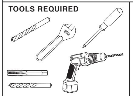
Self Drilling Screws Wood and Metal
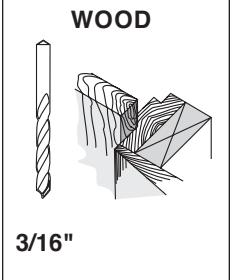
For woo d. drill 3/16" hole
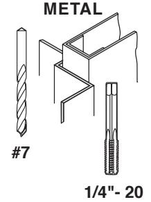
Machine Screws
#7 Drill, 1/4"- 20 Tap
Sleeve Nut and Bolt
Drill 9/32" thru from Clo ser Side 3/8" Drill otherSide
Check building and fire codes to see if your application requires the use of sleeve nuts and bolts.
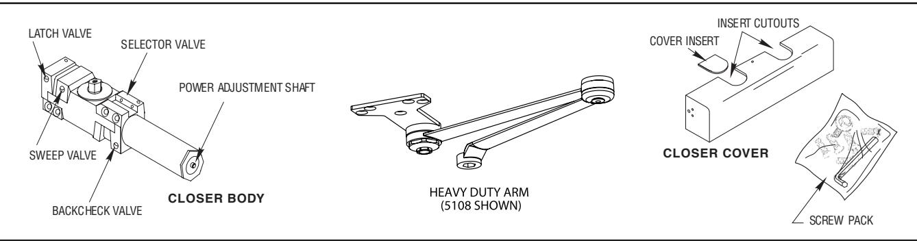
COMPONENT PARTS
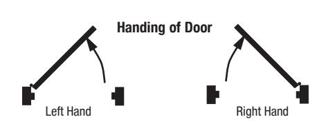
1. MARK AND DRILL HOLES (RIGHT HAND SHOWN)
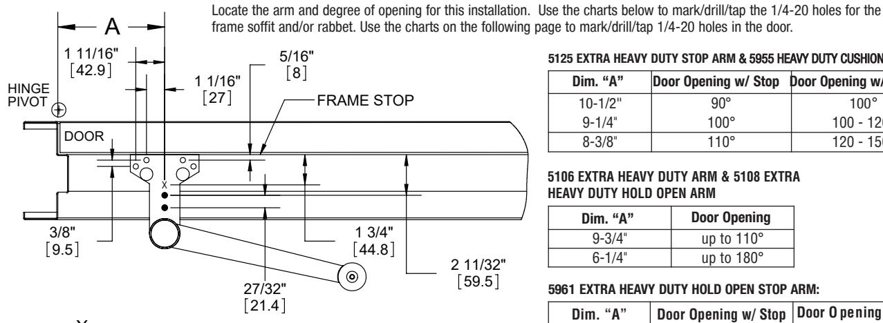
X PREP THIS HOLE IN THE FRAME SOFFIT OR RABBET IF USING THE 5106 OR 5108 ARM.
PREP THESE (2) HOLES IN THE FRAME SOFFIT OR RABBET IF USING THE 5105 OR 5960 ARM.
5125 EXTRA HEAVY DUTY STOP ARM & 5955 HEAVY DUTY CUSHION STOP ARM
| Dim. "A" | |||||
|---|---|---|---|---|---|
| Door Opening w/ Stop | Door Opening w/o Stop | ||||
| 10-1/2" | 90° | 100° | |||
| 9-1/4" | 100° | 100 - 120° | |||
| 8-3/8" | 110° | 120 - 150° | |||
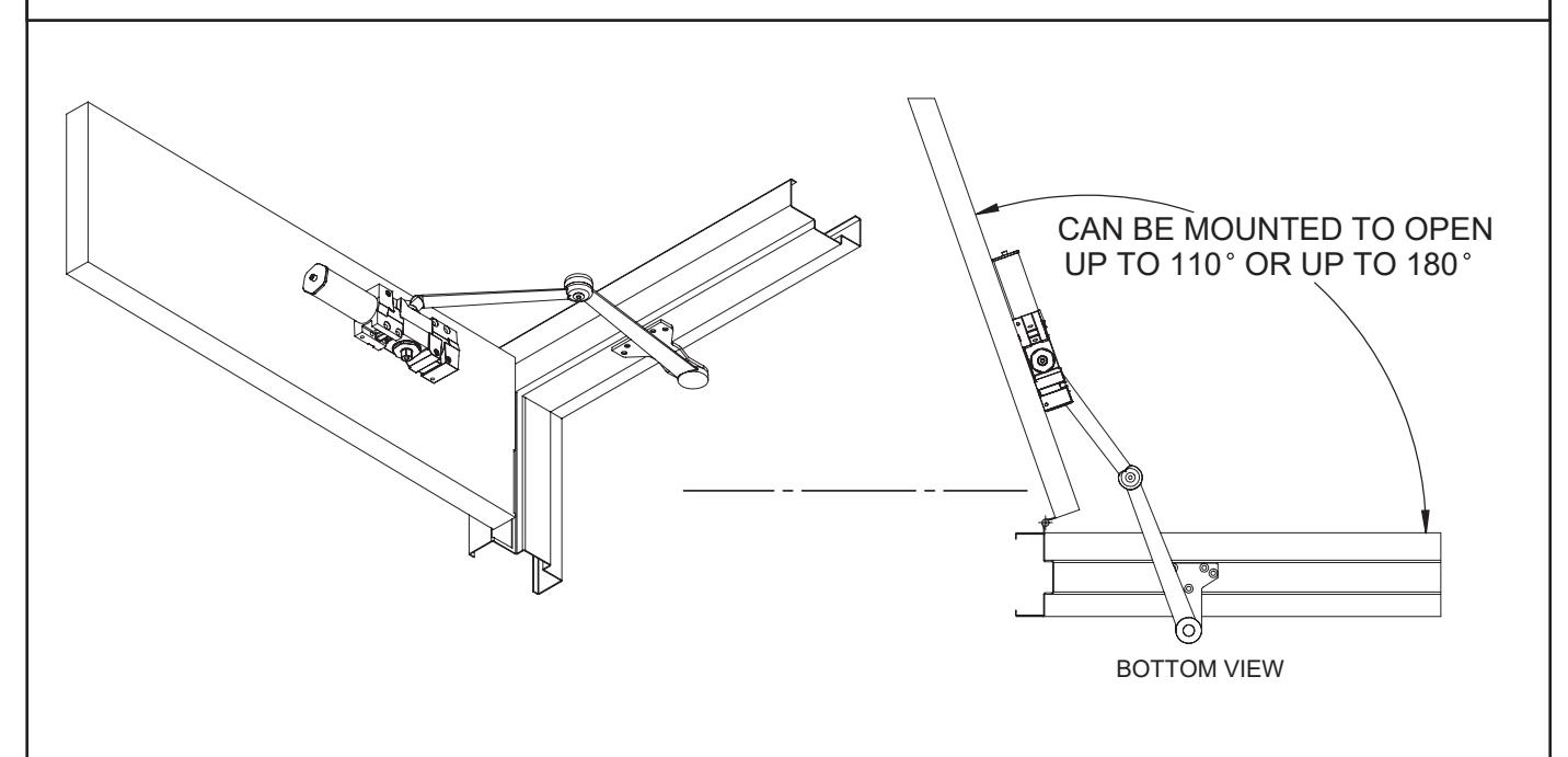
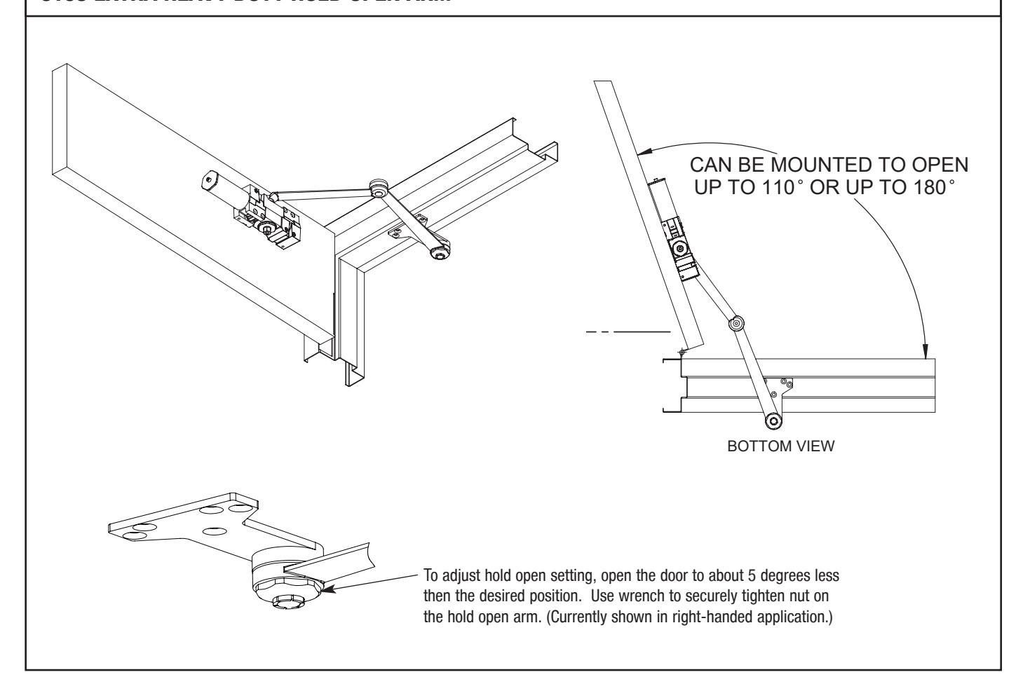
5106 EXTRA HEAVY DUTY ARM & 5108 EXTRA HEAVY DUTY HOLD OPEN ARM
| Dim. "A" | Door Opening | |
|---|---|---|
| 9-3/4" | up to 110° | |
| 6-1/4" | up to 180° | |
5961 EXTRA HEAVY DUTY HOLD OPEN STOP ARM:
| Dim. "A" | Door Opening w/ Stop | Door Opening w/o Stop |
|---|---|---|
| 10-7/16" | 90° | 100° |
| 9-1/4" | 100° | 100 - 120° |
| 8-3/8" | 110° | 120 - 150° |
REV: 4 REV DATE: 09/18/23 Page 1 of 6

1. MARK AND DRILL HOLES (CONTINUED)
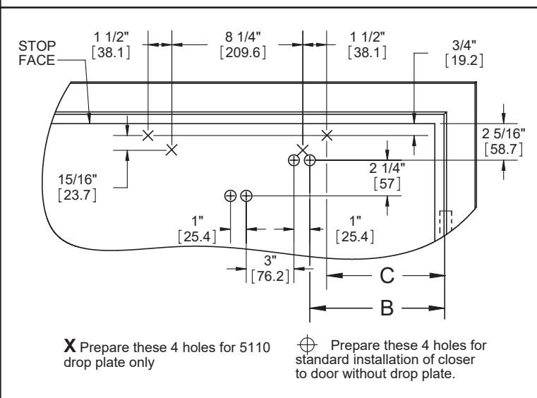
Note: Drop plate works with a minimum top rail of 2 1/2".
5125 Extra Heavy Duty Stop Arm, 5955 Heavy Duty Cushion Stop Arm & 5961 Extra Heavy Duty Hold Open Stop Arm:
| Dim. "B" | **Dim. "C" |
Door Opening
with Stop |
Door Opening
w/o Stop |
|---|---|---|---|
| 8-3/4" | 7-11/16" | 90° | 100° |
| 7-5/8" | 6-9/16" | 100° | 100 - 120° |
| 6-5/8" | 5-9/16" | 110° | 120 - 150° |
5106 Extra Heavy Duty Arm & 5108 Extra Heavy Duty Hold Open Arm:
| Dim. "B" | Dim. "C" | Door Opening |
|---|---|---|
| 8" | 6-15/16" | up to 110° |
| 4-1/2" | 3-7/16" | up to 180° |
** Needed only if using 5110 drop plate
2. ARM & CLOSER BODY INSTALLATION
Before mounting closers, make sure selector valve (found on back of closer) is screwed in.
- Screw body to the door using (4) 1/4-20 x 3" screws. The tube end of the closer must face the lock stile of door.
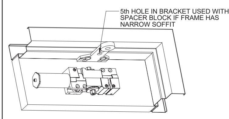
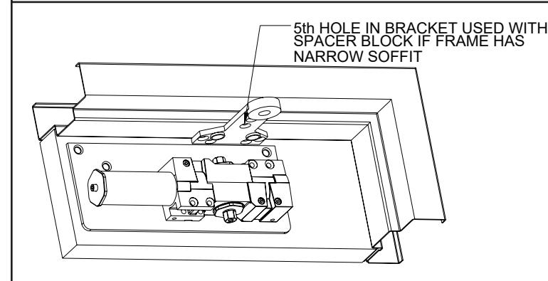
- Screw arm bracket to the frame soffit using (5) 1/4-20 x 1 1/2" screws. Do not tighten screws all the way to make mounting the arm to the closer easier.
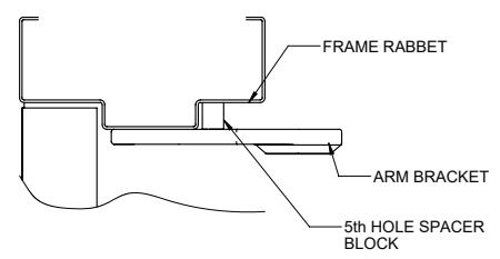
The fifth hole spacer shown above can be used when a narrow soffit prevents normal mounting. Drill/tap a 1/4-20 hole in the frame rabbet. Place the spacer between the bracket and frame and tighten using a 1/4-20 x 2" screw.
CLOSER BODY INSTALLATION (OPT DROP PLATE)
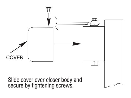
If using a drop plate, screw the drop plate to the door using 1/4-20 screws. Screw closer to the drop plate using 7/16" long machine screws.
REV: 4 REV DATE: 09/18/23 Page 2 of 6
* This table was made using 4 1/2" wide hinges. Use of larger hinges or swing clear hinges will yield different results.

3. MOUNT ARM TO CLOSER
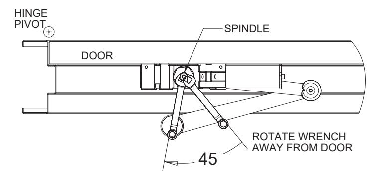
Use an adjustable wrench to rotate the bottom pinion shaft about 45 degrees in the direction away from the door.
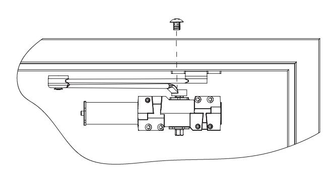
- Place arm on top pinion while holding pinion in position.
- Release hold on pinion shaft and attach arm to closer using pinion screw. Tighten bracket to frame if it was left loose during arm installation.
5125 EXTRA HEAVY DUTY STOP ARM & 5955 EXTRA HEAVY DUTY CUSHION STOP ARM (CUSHION STOP NOT SHOWN)
REV: 4 REV DATE: 09/18/23 Page 3 of 6

5106 EXTRA HEAVY DUTY ARM
5108 EXTRA HEAVY DUTY HOLD OPEN ARM
REV: 4 REV DATE: 09/18/2023 Page 4 of 6

5961 EXTRA HEAVY DUTY HOLD OPEN STOP ARM
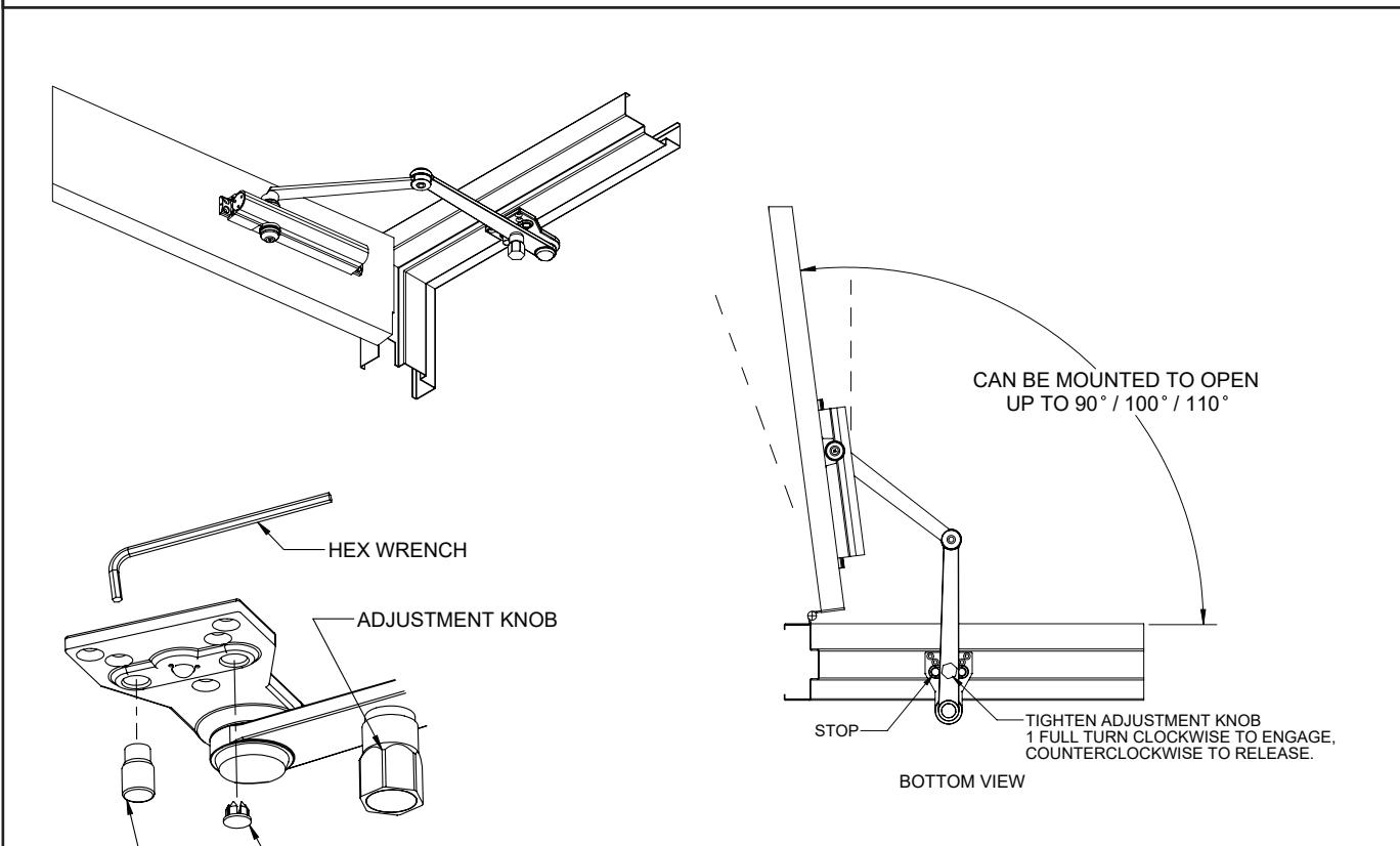
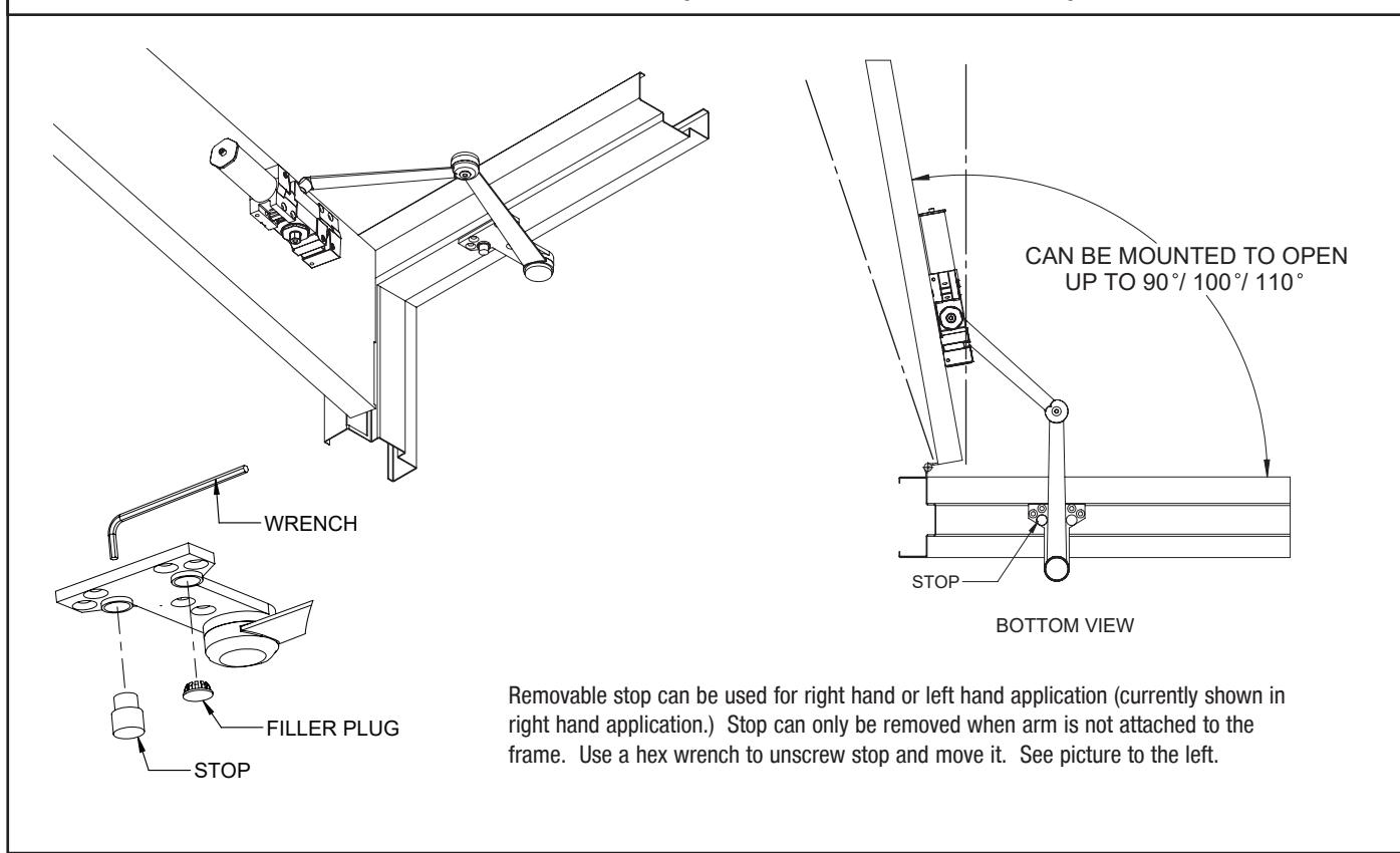
Removable stop can be used for right hand or left hand application (currently shown in right hand application). Stop can only be removed when arm is not attached to the frame. Use a 6mm wrench to unscrew stop and move it. See picture to the left. To engage hold open feature, open door to the stop and rotate adjustment knob clockwise to engage, counterclockwise to release.
See Adjustments on Page 6 for setting Spring Power, Sweep Speed, Latch Speed, and Backcheck.
NOTE: Do not fully unscrew valves or hydraulic fluid will leak and closer will no longer be functional.
STOP PLUG
4. ADJUSTMENTS 5. INSTALL COVER
REV: 4 REV DATE: 09/18/23 Page 5 of 6
0R

ADJUSTMENTS (USE 5/32" HEX WRENCH FOR THESE ADJUSTMENTS)
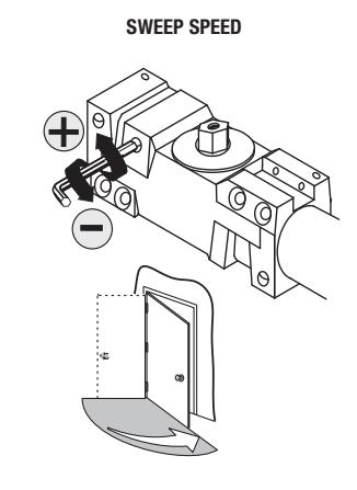
Note: Adjust closing time speed between 3 and 7 seconds from 90° to 0°. Greater closing times may be required for elderly or handicapped.
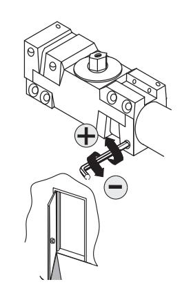
LATCH SPEED
Adjust latch speed so door completely closes and latches.
BACKCHECK
Adjust backcheck accordingly to prevent excessive opening speed.
OPTIONAL DELAY ACTION
Adjust delay action accordingly to obtain desired delay time.
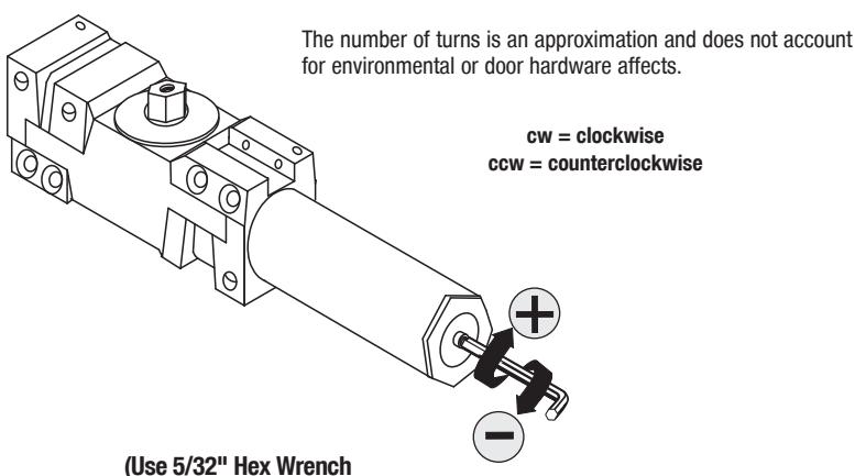
SPRING POWER ADJUST (SIZING IN ACCORDANCE TO BHMA/ANSI 156.4)
TABLE OF SIZES
Closer is shipped set to size 3. To change the closer size, use a hex wrench to rotate the spring power adjust. Follow the chart to make the correct number of 360° turns to set the closer size appropriately for the door application.
Exterior (and Vestibule) Door Width Minimum Door Width (24")
| Minimum Door Width (24") | |||||
|---|---|---|---|---|---|
| (610 |
4" - 3
mm) (762 |
- |
2" - 48
mm) (1219 |
_ | |
|
Regular Arm &
Top Jamb |
Size 3
(0) |
Size 4
(4cw) |
Size 5
(8cw) |
Size 6
(12cw) |
|
| Parallel Arm |
Size 3
(4cw) |
Size 4
(8cw) |
Size 5
(12cw) |
||
Interior Door Width
Minimum Door Width (24")
Regular Arm & Top Jamb
Parallel Arm
|
Size 1
(8ccw) |
Size 3
(0) |
Size 5
(8cw) |
|||
|
Size 1
(4ccw) |
Size 2
(0) |
Size 4
(8cw) |

An incorrectly installed or improperly adjusted door closer can cause property damage or personal injury. These installation instructions should be followed to avoid the possibility of misapplication or misadjustment.
for this adjustment)
REV: 4 REV DATE: 9/18/23 Page 6 of 6