I-CL00191 Instructions
Open the original PDF document
View PDF


An incorrectly installed or improperly adjusted door closer can cause property damage or personal injury. These installation instructions should be followed to avoid the possibility of misapplication or misadjustment.
- Hollow-metal doors require channel or box-type reinforcement when thru-bolt mount is specified.
- Hold open arms are not permitted on fire doors.
- Sex-bolts may be required for wood or plastic faced fire door mounting.
- Minimum thickness recommended for reinforcements in hollow metal doors and frames: (12GA).
- Dimensions are based on standard doors and frames with 1/8" clearance, 5/8" stops.
These door closers should NOT be installed on the exposed side (weather side) of exterior doors.
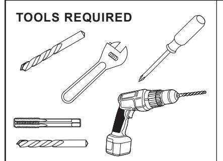
Self Drilling Screws Wood and Metal
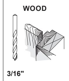
For wood, drill 3/16" hole
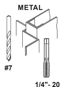
Machine Screws #7 Drill, 1/4"- 20 Tap

Drill 9/32" thru from Closer Side 3/8" Drill other Side
Check building and fire codes to see if your application requires the use of sleeve nuts and bolts.
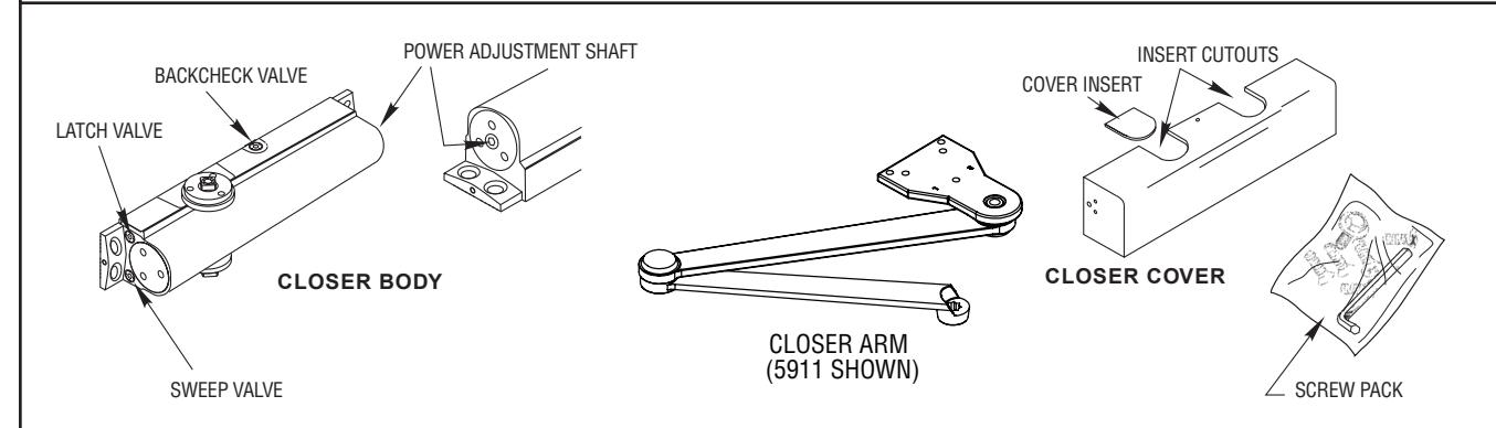
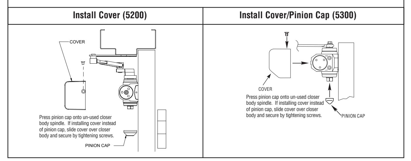
5200 CLOSER COMPONENT PARTS
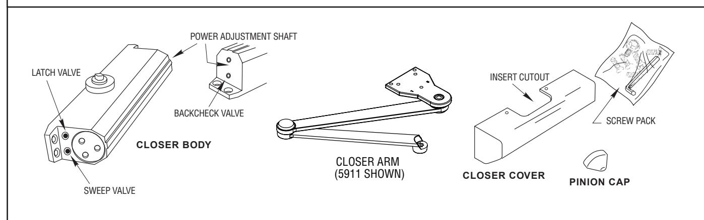
5300 CLOSER COMPONENT PARTS

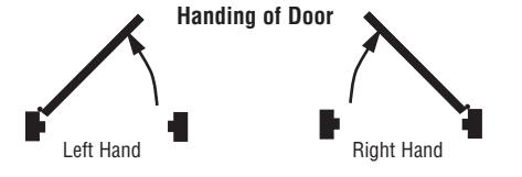
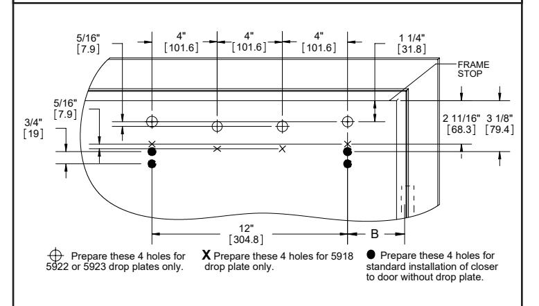
1. MARK AND DRILL HOLES (RIGHT HAND SHOWN)
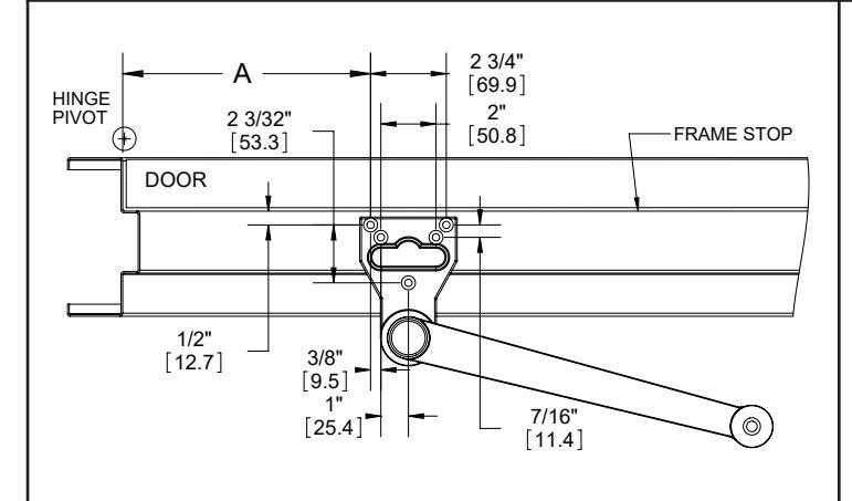
5200 DOOR CLOSER PREP. (RIGHT HAND SHOWN)
5300 DOOR CLOSER PREP. (RIGHT HAND SHOWN)
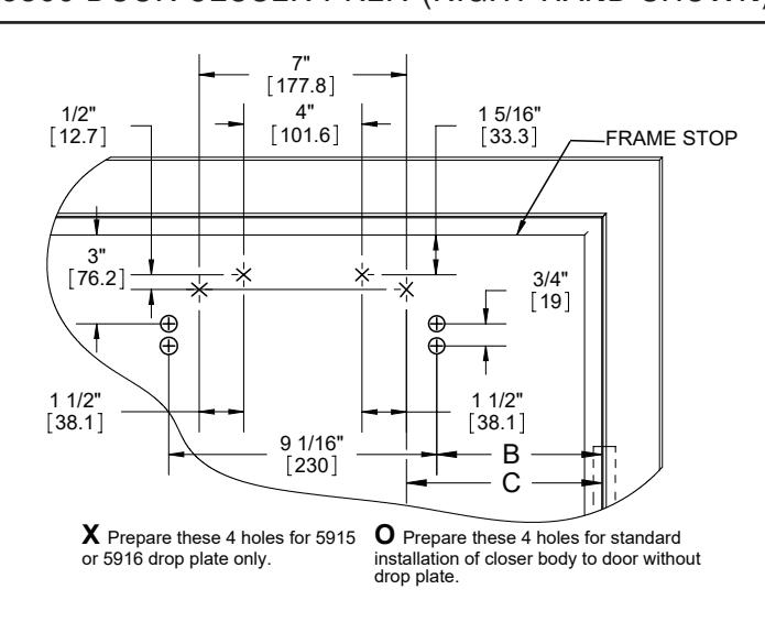
Locate the arm and degree of opening for this installation. Use the chart below to mark/drill/tap (4) 1/4-20 holes for the door. Also, mark/drill/tap (5) 1/4-20 holes in the frame soffit and/or rabbet.
5906 Extra Heavy Duty Hold Open Stop Arm, 5957 Heavy Duty Cushion Stop Arm, 5907 Extra Heavy Duty Stop Arm, & 5956 Extra Heavy Duty Hold Open Cushion Stop Arm:
5200 CLOSER MOUNTING CHART
| Dim. "A" | Dim. "B" |
Door Opening
with Stop |
Door Opening
w/o Stop |
|---|---|---|---|
| 10" | 4-1/2" | 90° | 105° |
| 8-3/4" | 3-1/2" | 100° | 105 - 130° |
| 7-1/2" | 2" | 110° | 130 - 170° |
5300 CLOSER MOUNTING CHART
| Dim. "A" | Dim. "B" | Dim. "C" |
Door Opening
with Stop |
Door Opening
w/o Stop |
|---|---|---|---|---|
| 10" | 8-1/8" | 9-1/8" | 90° | 105° |
| 8-1/2" | 6-1/2" | 7-1/2" | 100° | 105 - 130° |
| 7-1/2" | 5-7/16" | 6-7/16" | 110° | 130 - 170° |
5911 Extra Heavy Duty Arm & 5912 Extra Heavy Duty Hold Open Arm:
5200 CLOSER MOUNTING CHART
| Dim. "A" | Dim. "B" | Door Opening |
|---|---|---|
| 8-15/16" | 3-7/16" | up to 120° |
| 7-3/16" | 1-3/4" | up to 180° |
5300 CLOSER MOUNTING CHART
| Dim. "A" | Dim. "B" | Dim. "C" | Door Opening |
|---|---|---|---|
| 8-7/8" | 6-7/8" | 7-7/8" | up to 120° |
| 7-3/16" | 5-1/8" | 6-1/8" | up to 180° |
* This table was made using 4 1/2" wide hinges. Use of larger hinges or swing clear hinges will yield different results.
** Only use Dim "C" if using a drop plate.
| Drop Plate Part # | Minimum Top Rail | Closer |
|---|---|---|
| 5915 & 5916 | 3" | 5300 |
| 5918 | 4" | 5200 |
| 5922 & 5923 | 2-1/2" | 5200 |
Drop plate may be needed in special situations.
Page 2 of 6 REV: 4 REV DATE: 12/12/2023

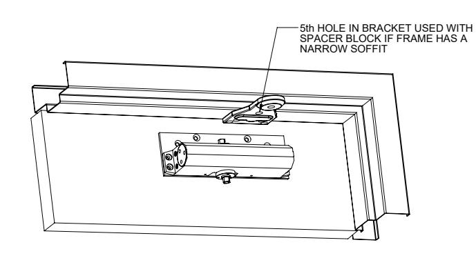
2. ARM AND CLOSER BODY INSTALLATION
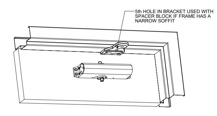
- Screw closer body to the door using (4) 1/4-20 x 1 1/2" screws. The speed regulating valves on the closer must face lock stile of door.
- Screw arm bracket to frame soffit using (5) 1/4-20 x 1 1/2" screws. Do not tighten screws all the way to make mounting the arm to the closer easier.
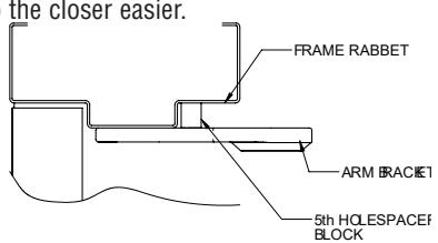
The fifth hole spacer shown above can be used when a narrow soffit prevents normal mounting. Drill/tap a 1/4-20 hole in the frame rabbet. Place the spacer between the bracket and frame and tighten using a 1/4-20 x 2" screw.
OPTIONAL DROP PLATE INSTALLATION
• If using a drop plate, screw the drop plate to the door using 1/4-20 screws. Screw closer to the drop plate using 7/16" long machine screws.
3. MOUNT ARM TO CLOSER
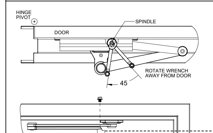
- Use an adjustable wrench to rotate the bottom pinion shaft about 45 degrees in the direction away from the door.
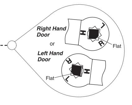
- Place arm on the top pinion shaft so that the "R" or the "L" is in line with the pinion flat as shown in the picture below.
- Attach the arm securely to the closer with the pinion screw. Tighten bracket to the frame if it was left loose during arm installation.
Page 3 of 6 REV: 4 REV DATE: 12/12/2023

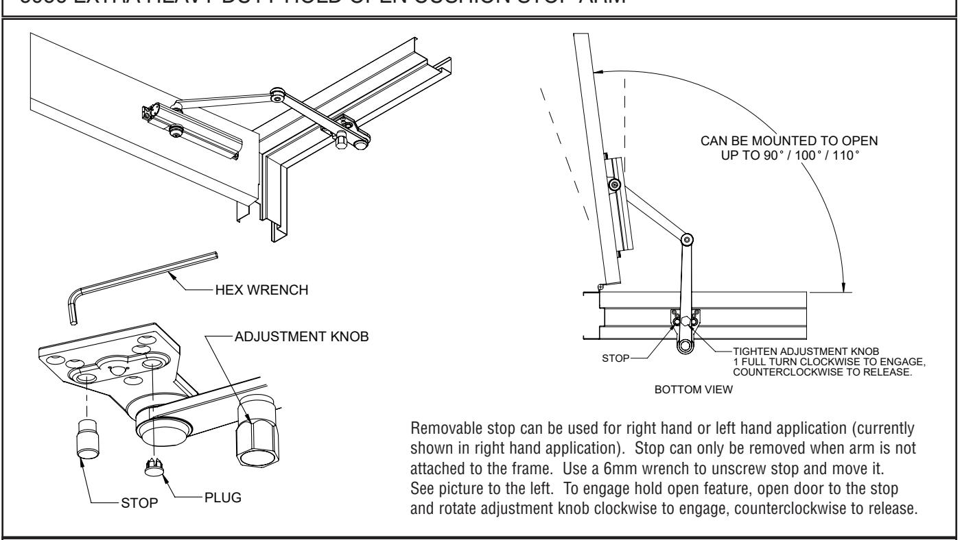
5906 EXTRA HEAVY DUTY HOLD OPEN STOP ARM & 5956 EXTRA HEAVY DUTY HOLD OPEN CUSHION STOP ARM
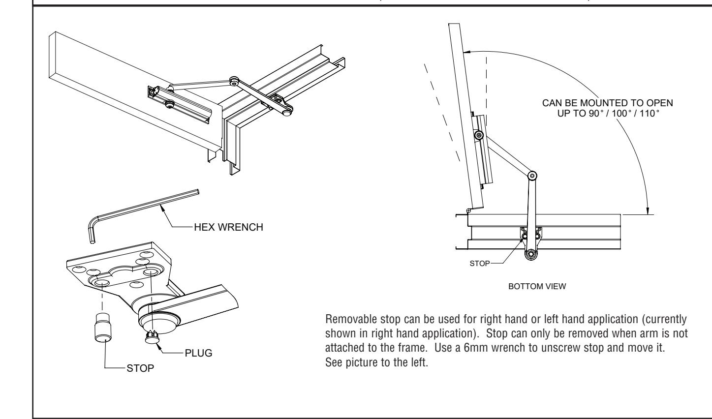
5907 EXTRA HEAVY DUTY STOP ARM 5957 EXTRA HEAVY DUTY CUSHION STOP ARM (CUSHION STOP NOT SHOWN)
Page 4 of 6 REV: 4 REV DATE: 12/12/2023

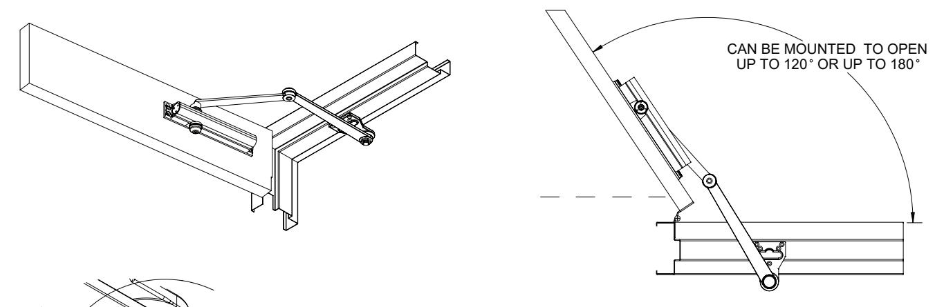
5911 EXTRA HEAVY DUTY ARM CAN BE MOUNTED TO OPEN UP TO 120° OR UP TO 180°
5912 EXTRA EXTRA HEAVY DUTY HOLD OPEN ARM
To adjust hold open setting, open the door about 20 degrees less than the desired position. Use a wrench to securely tighten the nut on the hold open arm. If the HO nut is not tightened firmly, the stop angle may be inaccurate or fail. To engage the HO, open the door to the HO angle range (From 10 degrees less than to the desired HO angle) and apply a strong push until it stops and holds.
REV: 4 REV DATE: 12/12/2023 Page 5 of 6

5300 CLOSER ADJUSTMENTS (USE 5/32" HEX WRENCH FOR THESE ADJUSTMENTS)
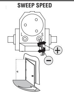
Note: Adjust closing time speed between 3 and 7 seconds from 90° to 0°. Greater closing times may be required for elderly or handicapped.
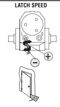
Adjust latch speed so door completely closes and latches
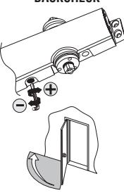
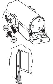
BACKCHECK
Adjust backcheck accordingly to prevent excessive opening speed.
SPRING POWER ADJUST (SIZING IN ACCORDANCE TO BHMA/ANSI 156.4)
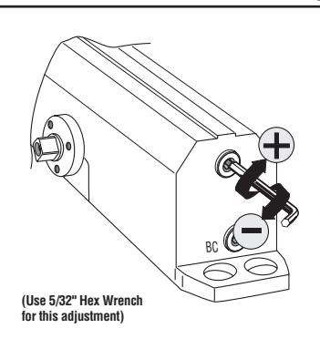
TABLE OF SIZES
Closer is shipped set to size 3. To change the closer size, use a hex wrench to rotate the spring power adjust. Follow the chart to make the correct number of 360° turns to set the closer size appropriately for the door application.
The number of turns is an approximation and does not account for environmental or door hardware affects.
Approx. 5 turns to
cw = clockwise ccw = counterclockwise
Exterior (and Vestibule) Door Width - 42"
| (610mm) (762mm) (914mm) (1067mm) (1219) | ||||||||
|---|---|---|---|---|---|---|---|---|
|
r Arm &
p Jamb |
Size 3
(0) |
Size 4
(5cw) |
Size 5
(10cw) |
Size 6
(15cw) |
||||
| llel Arm |
Size 3
(5cw) |
Size 4
(10cw) |
Size 5
(15cw) |
|||||
Interior Door Width
| or Width (24 | l") | |||||||
|---|---|---|---|---|---|---|---|---|
|
24" - 30" - 34" - 38" - 48" - 54" - 60"
(610mm) (762mm) (865mm) (965mm) (1219mm) (1372mm) (1524mm |
||||||||
|
Regular Arm &
Top Jamb |
Size 1
(10ccw) |
Size 2
(5ccw) |
Size 3
(0) |
Size 4
(5cw) |
Size 5
(10cw) |
Size 6
(15cw) |
||
| Parallel Arm |
Size 1
(5ccw) |
Size 2
(0) |
Size 3
(5cw) |
Size 4
(10cw) |
Size 5
(15cw) |
|||
5200 CLOSER ADJUSTMENTS (USE 5/32" HEX WRENCH FOR THESE ADJUSTMENTS)
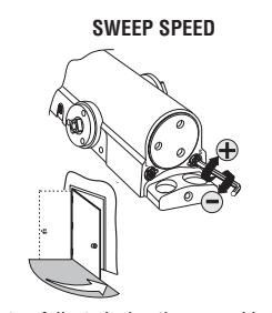
Note: Adjust closing time speed between 3 and 7 seconds from 90° to 0°. Greater closing times may be required for elderly or handicapped.
LATCH SPEED
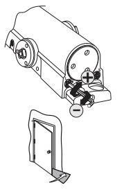
Adjust latch speed so door completely closes and latches
BACKCHECK
Adjust backcheck accordingly to prevent excessive opening speed.
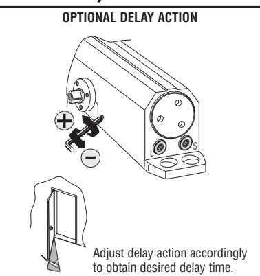
OPTIONAL DELAY ACTION
Adjust delay action accordingly to obtain desired delay time.
SPRING POWER ADJUST (SIZING IN ACCORDANCE TO BHMA/ANSI 156.4)
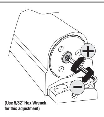
TABLE OF SIZES
Closer is shipped set to size 3. To change the closer size, use a hex wrench to rotate the spring power adjust. Follow the chart to make the correct number of 360° turns to set the closer size appropriately for the door application.
The number of turns is an approximation and does not account for environmental or door hardware affects.
Approx. 5 turns to increase / decrease one size.
cw = clockwise ccw = counterclockwise
Exterior (and Vestibule) Door Width
Interior Door Width
Size 3 (10cv
24" -30" 34" 38" 48" -
Size 4 (5cw) (5ccw) (0) Size 3 (5cw) Size 2 (0)