I-CL00177-Rev04
Open the original PDF document
View PDF

5100 Series Door Closer Installation Instructions
Grade 1 Meets ANSI A156.4


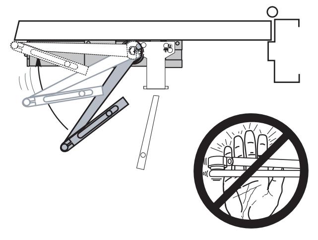
An incorrectly installed or improperly adjusted door closer can cause property damage or personal injury. These installation instructions should be followed to avoid the possibility of misapplication or misadjustment.
NOTE: For special applications, a separate door and frame preparation template is packed with these instructions. Use this instruction sheet for installation sequence and closer adjustments only.
- Dimensions are based on standard doors and frames with 1/8" clearance, 5/8" stops, and square edge doors.
- Door and frame must be properly reinforced.
- Non-Handed Door Closers.
- A mounting plate may be required for some applications.
- The regular Hold Open arm also follows these instructions.
Right Hand Door - RH Left Hand Reverse - LHR
• These door closers should NOT be installed on the exposed side (weather side) of exterior doors.
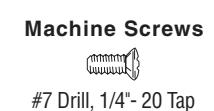
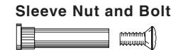
Drill 9/32" thru from Closer Side 3/8" Drill other Side
Check building and fire codes to see if your application requires the use of sleeve nuts and bolts.
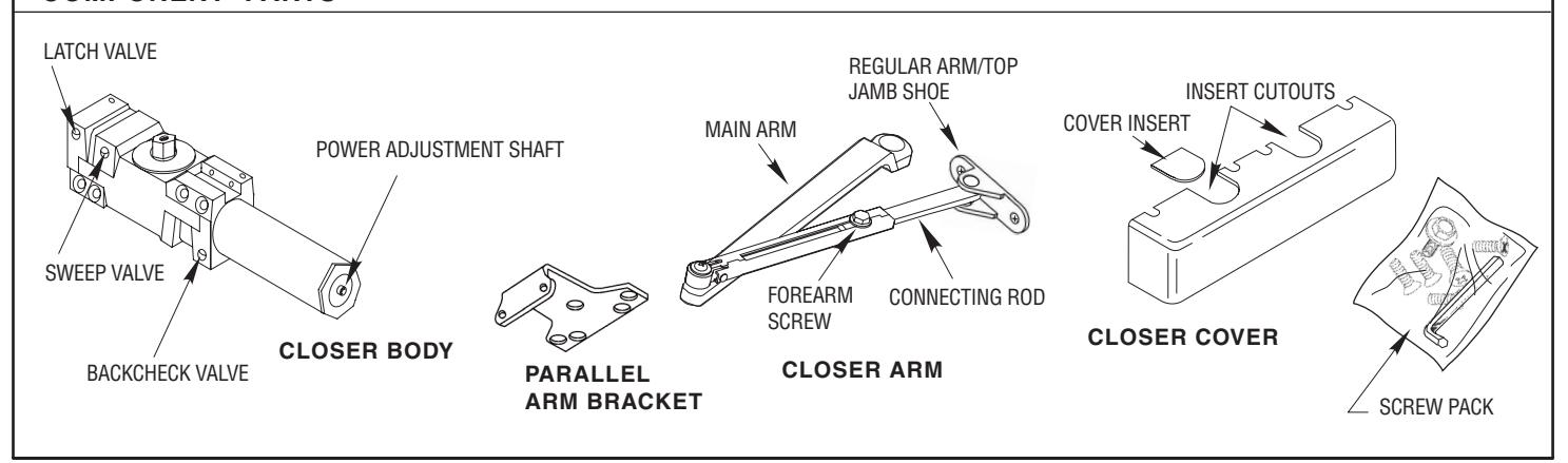
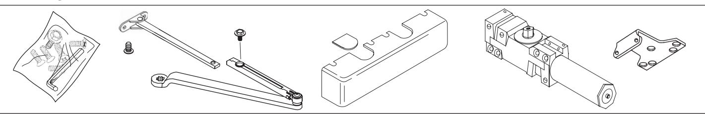
COMPONENT PARTS

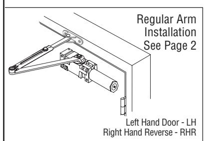
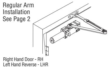
5100 Series Door Closer - Regular Arm Installation Instructions
Meets ANSI A156.4 I-CL00177
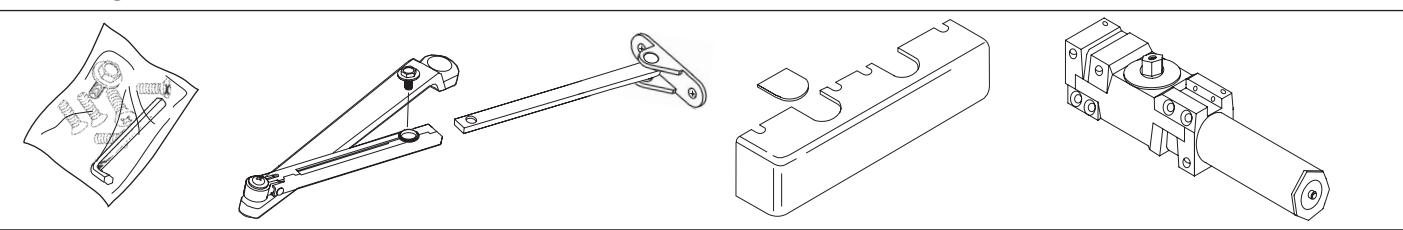
1. PARTS
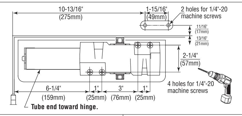
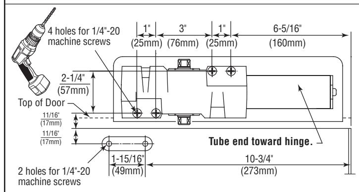
2. MARK AND DRILL HOLES ( Right Hand Shown)
120˚ Door Opening
An optional mounting plate is required when top rail is less than 3-3/4" (95 mm). Plate requires 2" (51mm) minimum top rail.
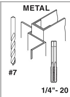
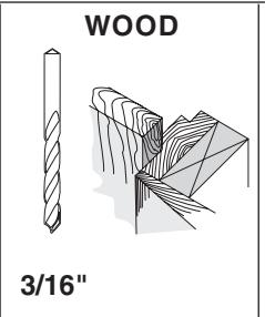
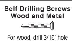
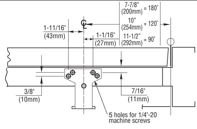
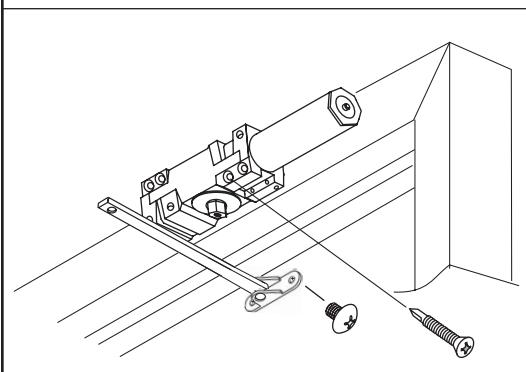
Select hand of door and degree of door opening. Fold template on the hinge edge of door line. Match this line with the hinge edge of door and attach template to door. Be sure frame line on template lines up with the bottom edge of frame face. Mark, prep and drill/tap 1/4"-20 holes for closer body and jamb shoe mounting screws.
3. INSTALL CLOSER
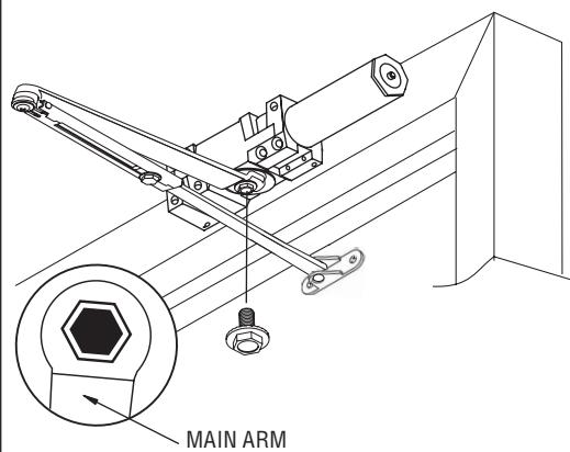
4. INSTALL MAIN ARM 5. INSTALL MAIN ARM AND CONNECTING ROD
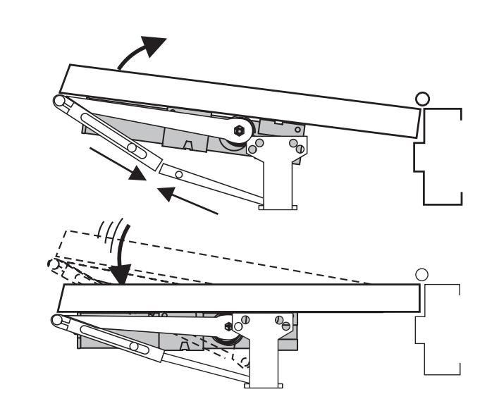
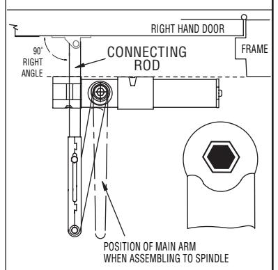
Slide connecting rod into forearm of main arm. Rotate main arm until connecting rod is at a 90˚ angle to frame. While holding arm in this position, tighten down forearm screw.
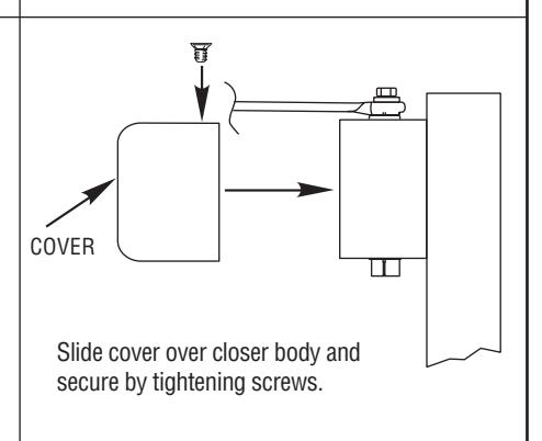
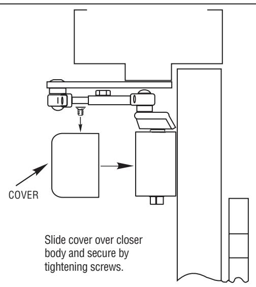
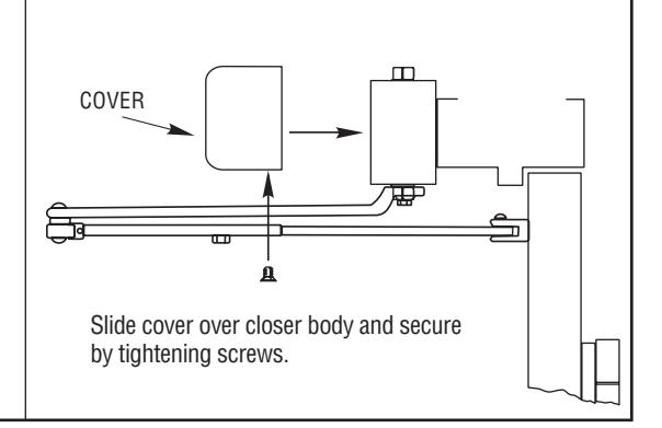
6. OPTIONAL HOLD-OPEN ARM 8. INSTALL COVER
Identify direction of hold-open nut according to hand of door and mount arm.
Adjust by loosening hold-open nut, then open door to desired position and tighten hold-open nut securely.
Note: Hold open arms must NOT be installed on fire-rated doors.
7. ADJUSTMENTS
See Adjustments on Page 6 for setting Spring Power, Sweep Speed, Latch Speed, and Backcheck.
NOTE: Do not fully unscrew valves or hydraulic fluid will leak and closer will no longer be functional.

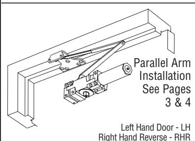
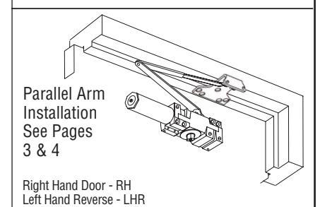
5100 Series Door Closer - Parallel Arm Installation Instructions
Meets ANSI A156.4 I-CL00177
1. PARTS
2. MARK AND DRILL HOLES ( Right Hand Shown)
Select hand of door. Fold template on the hinge edge of door line. Fold or cut upper corner illustrated on template and align template with the hinge edge of door. At the "Frame Stop Line" fold toward you and attach template to door. Mark, prep and drill/tap 1/4"-20 holes for closer body and parallel arm bracket mounting screws.
*Measured from frame Stop or pre-mounted jamb weatherstripping. Install before measuring closer hole locations.
An optional mounting plate is required where top rail is less than 5-1/2" (140mm). Plate requires 2" (51mm) minimum top rail.
3. INSTALL CLOSER
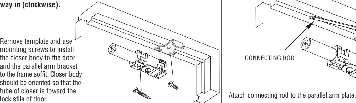
BEFORE INSTALLATION:
Turn backcheck selector valve (found on back side of closer) all the way in (clockwise).
Remove template and use mounting screws to install the closer body to the door and the parallel arm bracket to the frame soffit. Closer body should be oriented so that the tube of closer is toward the
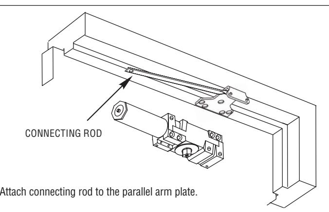
4. INSTALL CONNECTING ROD
5. INSTALL MAIN ARM
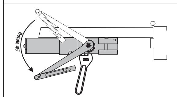
Use adjustable wrench to rotate spindle 45˚ counterclockwise for Right Hand Door or clockwise for Left Hand Door. Place main arm on spindle so that it is 45˚ or less from the tube end of the closer body. Secure main arm and spindle by tightening spindle bolt.

5100 Series Door Closer - Parallel Arm Installation Instructions
Meets ANSI A156.4 I-CL00177

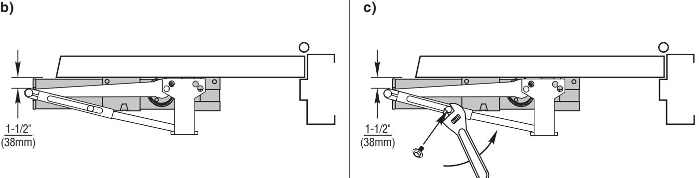
a)
Slide connecting rod into forearm of main arm.
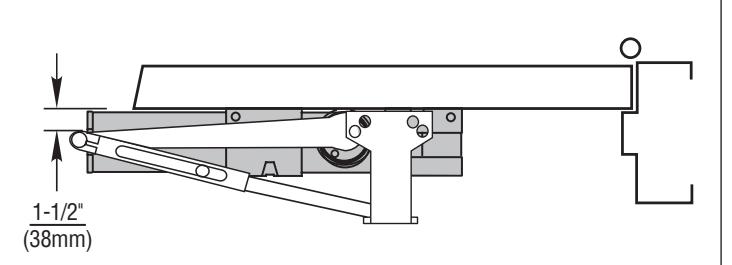
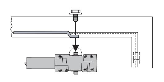
Rotate main arm until the pivot point is 1-1/2" from door surface. While holding arm in this position, tighten down forearm screw.
7. OPTIONAL HOLD-OPEN ARM 8. ADJUSTMENTS 9. INSTALL COVER
Identify direction of hold-open nut according to hand of door and mount arm.
Adjust by loosening hold-open nut, then open door to desired position and tighten hold-open nut securely.
Note: Hold open arms must NOT be installed on fire-rated doors.
See Adjustments on Page 6 for setting Spring Power, Sweep Speed, Latch Speed, and Backcheck.
NOTE: Do not fully unscrew valves or hydraulic fluid will leak and closer will no longer be functional.
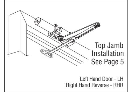
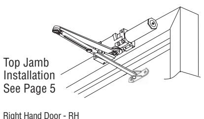
5100 Series Door Closer - Top Jamb Installation Instructions
Meets ANSI A156.4 I-CL00177
1. PARTS
2. MARK AND DRILL HOLES ( Right Hand Shown)
An optional mounting plate is required where the head frame face is less than 3-1/2" (89mm). Plate requires 1-3/4" (44mm) minimum head frame.
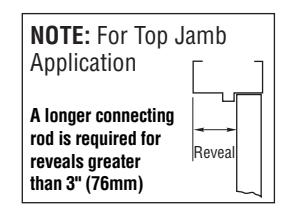
A longer connecting rod is required for reveals greater than 3" (76mm) Reveal
120˚ Door Opening
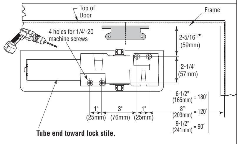
Select hand of door. Separate template sections "A" and "B". Fold template on the hinge edge of door line. Match this line with the hinge edge of door and attach template to door. Be sure "Frame" line on template lines up with the top edge of door. Using a square, project "Closer Projection Line" on section "A" of template onto frame and use to align and attach section "B". Be sure to align bottom edge of section "B" with edge of frame. Mark, prep and drill/tap 1/4"- 20 holes for connecting rod shoe and closer body mounting screws.
3. INSTALL CLOSER
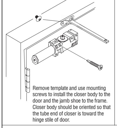
Remove template and use mounting screws to install the closer body to the top jamb and the connecting rod shoe to the door. Closer body should be oriented so that the tube end of closer is toward the hinge stile.
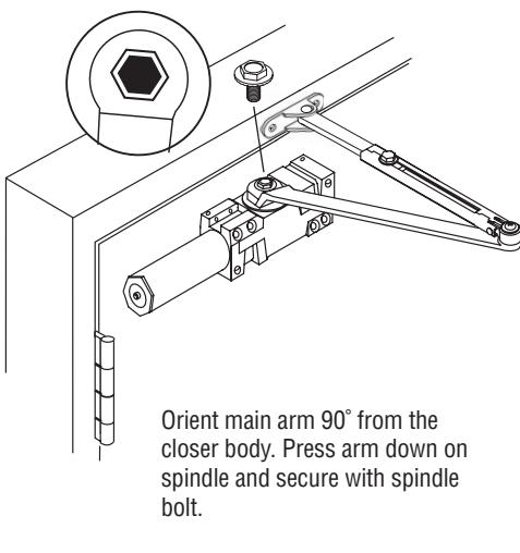
Orient main arm 90˚ from the closer body. Press arm down on spindle and secure with spindle bolt.
4. INSTALL MAIN ARM 5. INSTALL MAIN ARM AND CONNECTING ROD
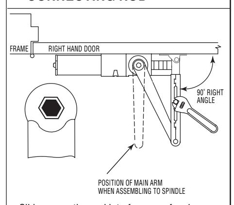
Slide connecting rod into forearm of main arm. Rotate main arm until connecting rod is at a 90˚ angle to frame. While holding arm in this position, tighten down forearm screw.
6. OPTIONAL HOLD-OPEN ARM 7. ADJUSTMENTS
Identify direction of hold-open nut according to hand of door and mount arm.
Adjust by loosening hold-open nut, then open door to desired position and tighten hold-open nut securely.
Note: Hold open arms must NOT be installed on fire-rated doors.
See Adjustments on Page 6 for setting Spring Power, Sweep Speed, Latch Speed, and Backcheck.
NOTE: Do not fully unscrew valves or hydraulic fluid will leak and closer will no longer be functional.
8. INSTALL COVER

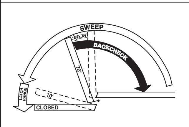
ADJUSTMENTS (USE 5/32" HEX WRENCH FOR THESE ADJUSTMENTS)
SWEEP SPEED
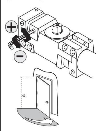
Note: Adjust closing time speed to between 3 and 7 seconds from 90 to 0. Greater closing times may be required for elderly or handicapped.
LATCH SPEED
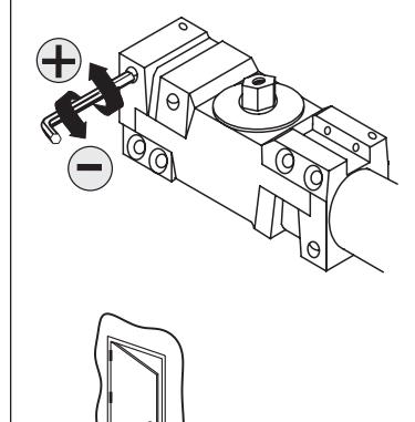
Adjust latch speed so door completely closes and latches.
BACKCHECK
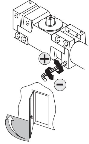
Adjust backcheck accordingly to prevent excessive opening speed.
OPTIONAL DELAY ACTION
Adjust delay action accordingly to obtain desired delay time.
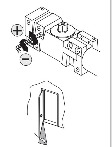
SPRING POWER ADJUST (Sizing in accordance to BHMA/ANSI 156.4)
TABLE OF SIZES
Closer is shipped set to size 3. To change the closer size, use a hex wrench to rotate the spring power adjust. Follow the chart to make the correct numbers of 360° turns to set the closer size appropriately for the door application.
The number of turns is an approximation and does not account for environmental or door hardware affects.
cw = clockwise ccw = counterclockwise
Exterior (and Vestibule) Door Width
| Minimum Door Width (24") | |||||||||
|
24" - 30" - 36" - 42" - 4
(610mm) (762mm) (914mm) (1067mm) (1219 |
|||||||||
|
Regular Arm &
Top Jamb |
Size 3
(0) |
Size 4
(5cw) |
Size 5
(10cw) |
Size 6
(15cw) |
|||||
| Parallel Arm |
Size 3
(5cw) |
Size 4
(9cw) |
Size 5
(14cw) |
||||||
| ır | ter | ior D | oor | Widi | tn | ||||||||
|---|---|---|---|---|---|---|---|---|---|---|---|---|---|
| M | inim | um Do | or Wid | dth (24 | ") | _ | |||||||
| _ | 4" - | 0. | _ | _ | • | _ | • | _ | • | • | _ | ||
| (610 |
lmm)
| |
1297)
I |
mm) | (865 |
mm)
I |
(965 |
mm)
| |
(1219 |
9mm)
I |
(1372 |
!mm)
| |
(1524 |
lmm
I |
| _ | _ | _ | _ | 1 |
Regular Arm & Top Jamb Parallel Arm
| 1 | Size 1 | Size 2 | Size 3 | Size 4 | Size 5 | Size 6 |
|---|---|---|---|---|---|---|
| (5ccw) | (2ccw) | (0) | (5cw) | (10cw) | (15cw) | |
|
Size 1
(4ccw) |
Size 2
(0) |
Size 3
(5cw) |
Size 4
(9cw) |
Size 5
(14cw) |
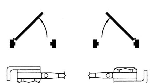
ADJUSTMENT DIAGRAM
(Use 5/32" Hex Wrench
for this adjustment)
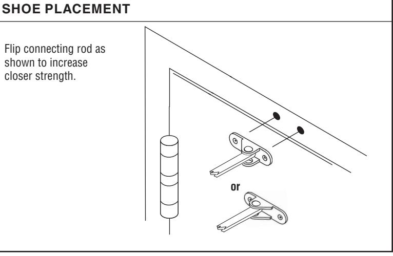
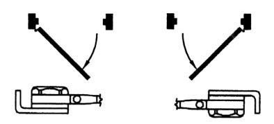
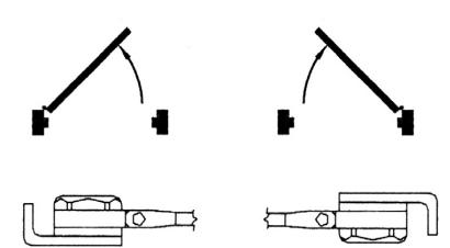
Flip connecting rod as shown to increase closer strength.