HiTower Z, S, I, D, P, H & T 7500 Series Installation Instructions
Open the original PDF document
View PDF801 Avenida Acaso, Camarillo, Ca. 93012 • (805) 494-0622 • Fax: (805) 494-8861 www.sdcsecurity.com • E-mail: service@sdcsecurity.com
INSTALLATION INSTRUCTIONS HiTower® Z, S, I, D, P, H & T 7500 SERIES
For the door portion follow the enclosed mortise lock instructions
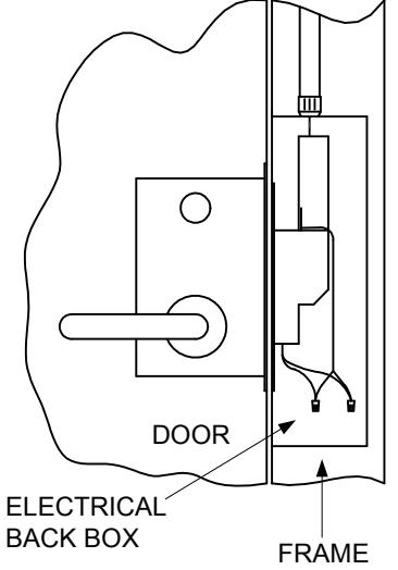
For the frame portion (electric actuator) read these instructions carefully.
To insure a neat and easy installation of the electric actuator into the frame back box when making long wire runs, the heavier gauge wire can be terminated in a junction box above the door. At this point a smaller gauge wire cable may be run from the junction box to the frame electrical black box. This provides for easier insertion of the electric actuator.
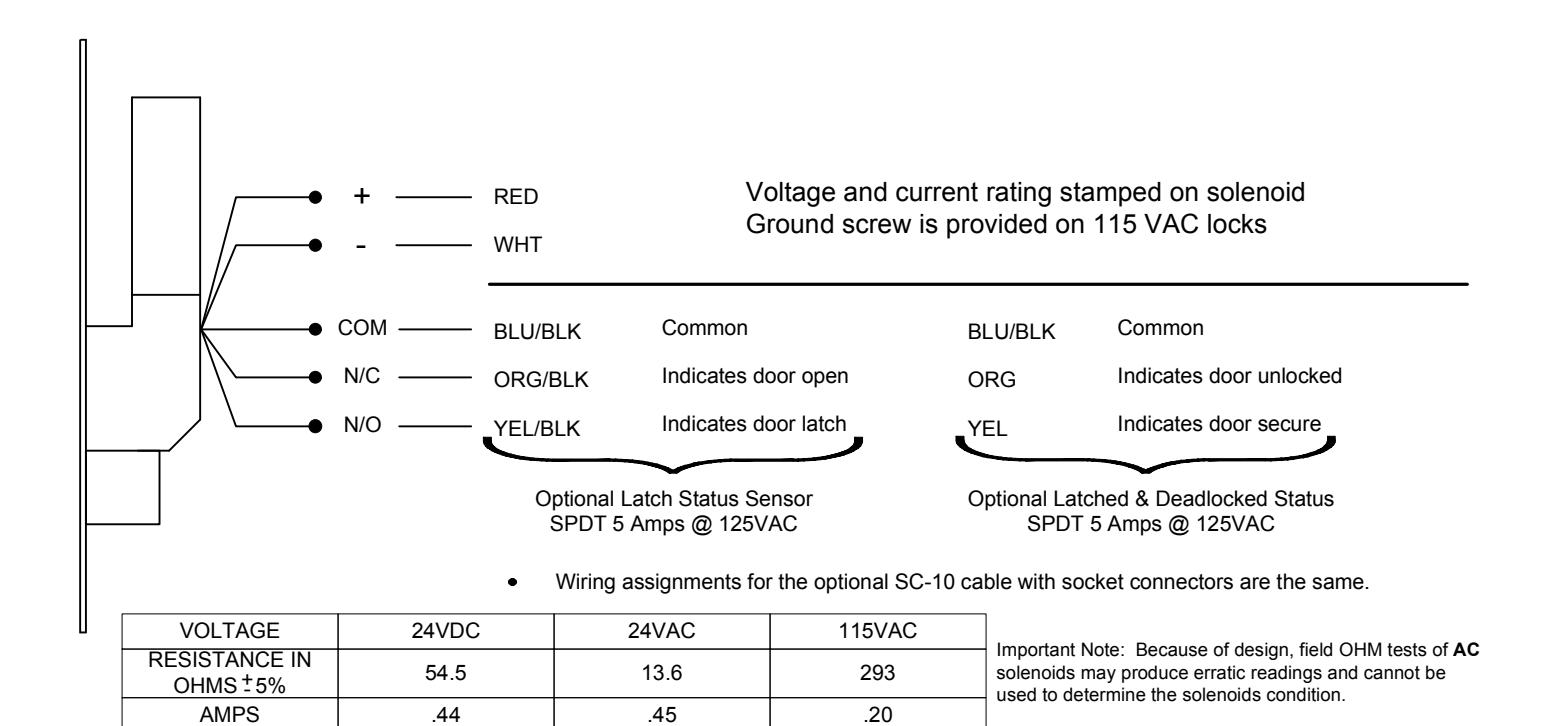
For proper operation the voltage as indicated on the lock solenoid must be at the lock location with the load on.
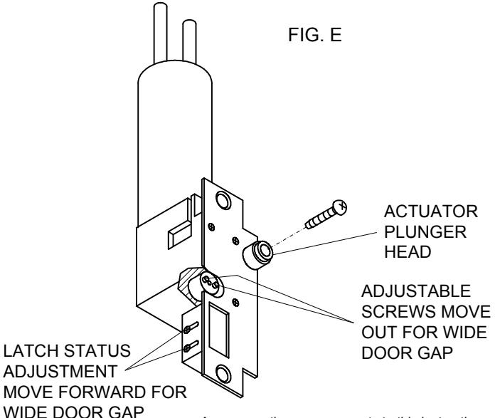
Latch position sensor adjustment is set for 1/8" door clearance and is adjustable for wide and narrow door gaps. Make this adjustment before installing.
To make adjustment please follow steps A, B & C. Refer to Fig. E.
- A. Loosen the two screws on the side of the dust box.
- B. Move the switch assembly forward or back to desired position. Example: For 3/16" door gap move the switch assembly forward 1/16".
- C. Tighten screws.
- The wiring assignments are shown on the reverse side of this page as well as on the electric actuator. The lock is supplied with 6" wire leads and will require 10" leads from the conduit.
- Attach power supply leads to lock leads as shown. Wire nuts are sufficient for these connections.
- Insert wires into the jamb carefully so they do not interfere with proper positioning of the lock in the cut-out.
- 5. Insert lock and secure with screws provided.
-
6. With the power on to the electric actuator, check to see if the levers are locked. On 7540 and 7550 models only the outside lever should lock. The actuator is set for 1/8" door clearance as shipped from the factory. If the clearance between the door and jamb is more or less than 1/8" the following adjustment must be made (refer to Fig. E).
- A. Loosen the allen screw in the plunger.
- B. Remove plunger head.
- C. Turn each adjustment screw equally in desired direction. Counter-clockwise for wide gaps clockwise for narrow gaps.
IMPORTANT: ADJUSTMENT SCREWS MUST BE TURNED EQUALLY TO OPERATE FREELY.
D. Replace plunger head and test lock. Lever should lock when actuator is energized.
Strike Plate Dimensions
For Metal Frames: 4-7/8" x 1-1/4" x .0937" Standard ANSI For pairs of wood doors or wood frames: 9-1/2" X 1-1/4" x 1/8" For narrow metal frames: 8-1/2" x 1-1/4" x 1/8"
ID Requirements
Standard Actuator: 12" x 2-1/2" x 1-3/4" Narrow Backset Actuator: 12" x 2-1/2" x 1-1/4"
Fail Safe: Continuous duty – locked when energized UL Listed: Electrically controlled single point locks or latches
Electric Actuator. Solenoid points up when actuator is used
with:
| WILIT: | |
|---|---|
| SOURCE | MODEL |
| Z SDC | 7550 |
| S SCHLAGE | L9080 |
| I CORBIN/ | ML2057 |
| RUSSWIN | |
| D SARGENT | 8200 |
| P YALE | 8805 |
| T BEST | 45H |
| H HAGER | 3880 |
Any suggestions or comments to this instruction or product are welcome. Please contact us through our website or email engineer@sdcsecurity.com
| FUNCTIONS |
|---|
7510 Mortise lock is unlocked by means of a remote switch.
Suggested: storerooms, records, utility, tool cribs, man trap.
7520 Mortise lock is unlocked by remote switch or by means of an outside key. Suggested: storerooms, records, utility, tool cribs, man trap.
7530 Mortise lock is unlocked by a remote switch or by means of a key from either side. Suggested: communicating locks, man trap
7540 Mortise lock is unlocked by a remote switch or by rotating the inside lever which retracts the mortise latch bolt and the auxiliary latch. Suggested: stairtower doors, control
centers, vaults, man trap.
7550 Mortise lock is unlocked by remote switch or by means of an outside key or by rotating the inside lever.
Suggested: stairtower doors, classrooms, laboratories, offices, man trap.
TROUBLE SHOOTING HiTower 7500 SERIES R
The 7500 Series is a (PL) Electric Power to Lock Unit which is failsafe in that it unlocks when power is removed. The most commonly used function is the 7540 and 7550 models which are locked when energized on the outside and free on the inside egress. Models 7510, 7520 & 7530 lock on both sides when energized.
| PROBLEM | CAUSE | SOLUTIONS | |
|---|---|---|---|
| (1) | Power on controller plunger does not throw. | 1A Insufficient voltage |
1A Check voltage with a meter at the lock
farthest from source with all locks energized. Meter should indicate the same voltage stamped on the solenoid body. If voltage is low, either too small of a wire gauge was used or there is too great of a load on the line. |
|
1B Binding caused by uneven
plunger adjustment. |
1B Adjust plunger evenly. | ||
| 1C Electric portion wired wrong. |
1C Review wiring diagram on side of lock &
instruction sheet. |
||
| (2) |
Latch bolt throws only part way, lock
chatters or buzzes. |
2A Door alignment does not
permit latch bolt to enter strike |
2A Proper alignment must be achieved by correctly
hanging the door in a properly installed frame. Modifying the lock and strike will not remedy the problem. Modification will only void UL listing and warranty. |
| (3) | Inside lever is locked, outside is free. | 3A Incorrect handing | 3A Remove mortise lock and reverse hand. |
| (4) |
Latch position switch does not signal
properly. |
4A 9A adjustment is off. | 4A Adjust sensor. See Step 1 of instructions. |