HS4 RFnet Gateway Controller Installation Instructions 221135
Open the original PDF document
View PDF

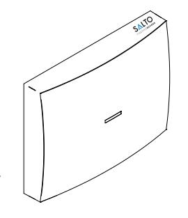
Gatewayx2
Description
The Gateway is the link between the PC and SALTO´s wireless network RF2 (wireless escutcheons). It gives real-time information to the PC.
Gateways are completely managed through the SALTO Software, it collects all the information sent by escutcheons that belong to the Gateway. It has been designed with PoE technology, capable of power the Gateway through Ethernet infrastructure.
Descripción
El Gateway hace de enlace entre el PC o servidor, donde se aloja la base de datos (conexión Ethernet estándar RJ45) y la red wireless RF2 de SALTO (escudos wireless). Los Gateways son gestionados a través del softwares de última generación de SALTO Systems, permitiendo que los operadores gestionen y se comuniquen de forma sencilla y segura con todos los puntos de acceso wireless. Dispone de tecnología PoE que le permite alimentarse a través de la infraestructura Ethernet.
Electrical characteristic
Características Eléctricas
Operation conditions
| Min | Typ | Max | Unit | |
|---|---|---|---|---|
| Temperature | 0 | 25 | 60 | ºC |
| Humidity | 35 | 85 | % |
Cable requirements
| Ethernet | UTP CAT5e |
|---|---|
| Node Connection (AB) |
Generic twisted pair wire
Note1 |
| Node Connection (Vdd) | 24 AWG |
RF Characteristics (if internal node installed)
| Frequency Range | 2405-2480 Mhz |
|---|---|
| RF Standard | IEEE 802.15.4 |
| Indoor Radio Range | 10/15m |
PoE ( IEEE802.3af )
| Unit | ||
|---|---|---|
| Class | 2 | |
| MaxPower | 5 | W |
| Ethernet Standard | 10 BASE-T/100 BASE-TX | |
Auxiliary Power Supply
| Min | Typ | Max | Unit | |
|---|---|---|---|---|
| Input Voltage Note 2 | 10 | 12 | 15 | V |
| Current consumption |
75
Note 3 |
375 Note 4 | mA |
Note 1: 1x2x24AWG or UTP CAT5e recommended Note 2: Use provided AC-DC power supply Note 3: No external/internal node connected
Note 4: 6 external node connected

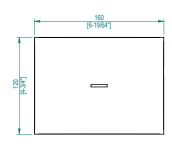
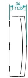
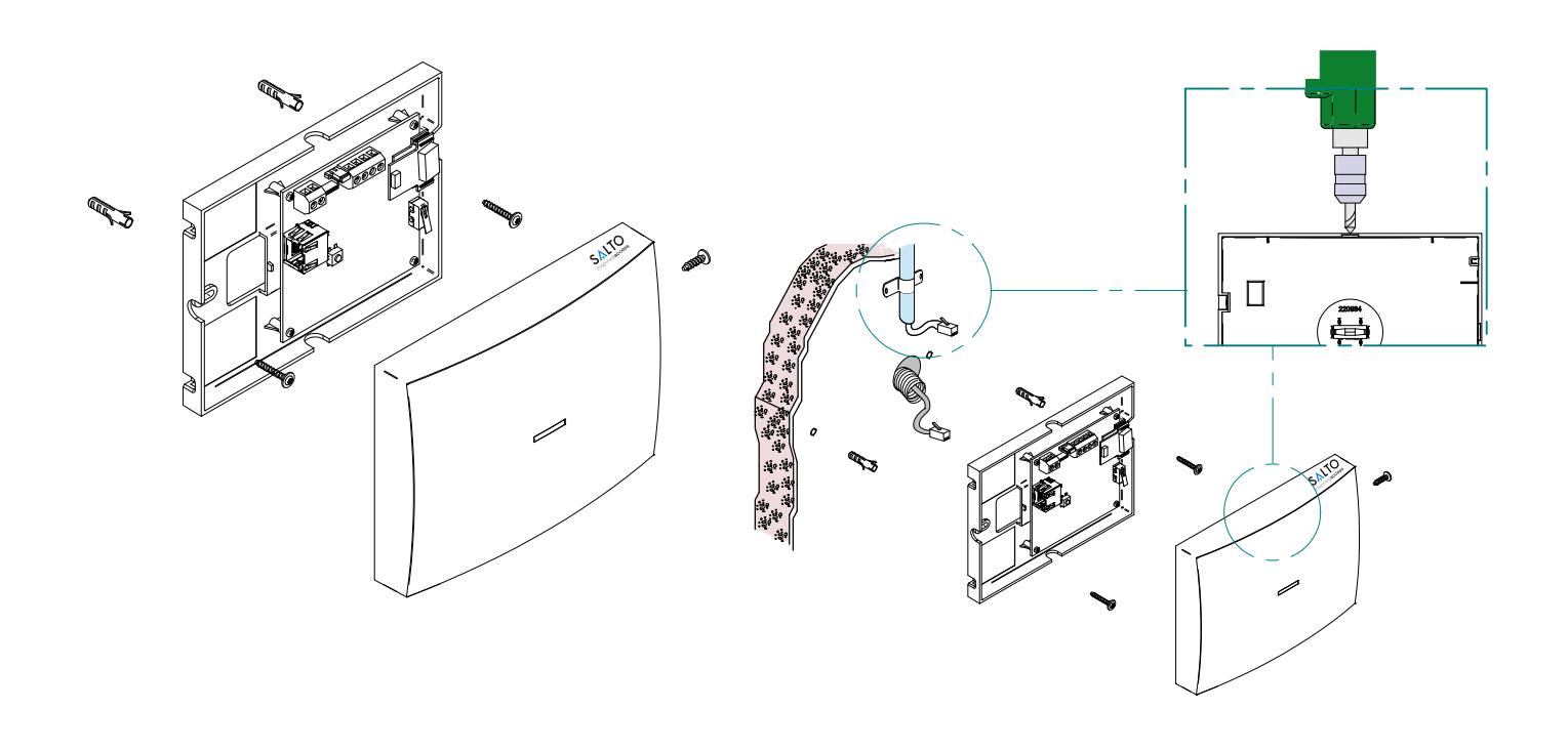
Mechanical Installation
Instalación Mecánica
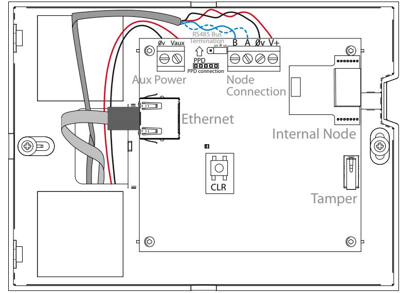
Electrical Installation
Instalación Eléctrica

-
When PoE and auxiliary power supplies are connected at the same time, PoE is disconnected.
- Pressing CLR button 5 seconds, Gateway enters in addressing mode.
- La alimentación auxiliar prevalece sobre la alimentación PoE en caso de conectar las dos a la vez.
- Pulsando el botón CLR 5 segundos el Gateway entra en modo direccionamiento.

RS48 5 bus termination resistor is needed (ON position) when the node is located at the end of the bus.
La resistencia de terminación del bus RS485 es necesaria (posición ON) cuando el equipo esté situado en uno de los extremos del bus

- Auxiliary power supply needed when Ethernet infrastructure is not PoE (Power over Ethernet)
- La alimentación auxiliar sólo es necesaria cuando la infraestructura Ethernet no cuente con soporte PoE (Power Over Ethernet)

Configuration
Configuración
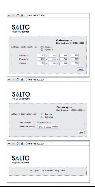
Addressing and configuration
Gatewayx2 is a DHCP ready device. If there is no DHCP server on the local Ethernet network, user can manually configure a fixed IP address changing different parameter using Gatewayx2 Web Server:
- 1. Pressing CLR button for 5 seconds, Gatewayx2 enters in addressing mode (green LED turns to orange).
- 2. Access to 192.168.0.234 IP address with a standard browser and configure network parameters as needed.
- 3. Pressing again CLR button for 5 seconds or confirming the configuration, the device is going to quit the addressing mode.
When addressing process success, configure the RF2 network with SALTO´s software (check the help of the application).
Direccionamiento y configuración
El Gatewayx2 es un dispositivo que dispone de DHCP. Si no existe un servidor DHCP en la red local Ethernet, el usuario puede configurar una IP fija cambiando diferentes parámetros utilizando el Gatewayx2 Web Server:
- 1. Pulsando el botón CLR 5 segundos el Gateway entra en modo direccionamiento (pasa del LED verde al naranja).
- 2. Acceder a la dirección IP 192.168.0.234 a través de un navegador web estándar y configurar los parámetros de red.
- 3. Pulsando otra vez el botón de CLR 5 segundos o confirmando la configuración, el dispositivo saldrá del modo direccionamiento.
Una vez direccionado, configurar la red RF2 a través del software de SALTO (consultar la ayuda del programa).
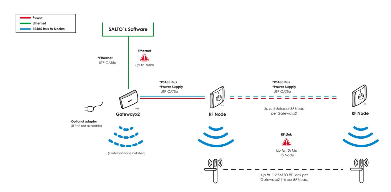
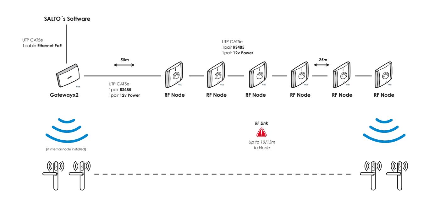
Installation Example
Ejemplo de Instalación

Signalling
Señalización
The LED in the top layer of the Gateway shows the state of the system:
| LED colour | Description |
|---|---|
| No light | Lack of power supply |
| Green | Everything is ok |
| Orange | Gateway in 'Addressing Mode' state |
| Red | Gateway in 'Bootloader mode' state |
| Flashing Green | No initialized by SALTO´s software |
The LEDs on the Ethernet Connector show the state of the Ethernet communication:
| LED colour | Description |
|---|---|
| No light | No Ethernet connection |
| Green | Ethernet active |
| Flashing orange | Data transfer taking place through Ethernet. |
Los LEDs del Gateway indican en todo momento el estado del sistema:
| Color LED | Descripción |
|---|---|
| No luz | Alimentación no presente |
| Verde | El sistema funciona correctamente |
| Naranja | El Gateway está en "Modo Direccionamiento" |
| Rojo | El Gateway está en "Modo Bootloader" |
| Parpadeo Verde | No inicializado por el software de SALTO |
Los LEDs situados en el conector Ethernet indican el estado de la conexión:
| Color LED | Descripción |
|---|---|
| No luz | Sin conexión Ethernet |
| Verde | Ethernet activo |
| Parpadeo Naranja | Transferencia de datos activa |
Operational test
Test Operacional
Maintenance
Mantenimiento
Once the product is installed, follow these steps to check the correct operation:
- Visually check that the LED is active after power on.
- When nodes and locks are installed, check that the LED is green.
- Check Ethernet connector LED to know communication state.
Una vez instalada la unidad de control, para comprobar el correcto funcionamiento de la instalación, siga los siguientes pasos:
- Comprobar visualmente que al alimentar el equipo el LED está activo.
- Comprobar que al instalar los nodos y las cerraduras el LED está en verde.
- Para saber el estado de la conexión Ethernet, comprobar el estado de los LEDs.
- This unit should be tested at least once a year as described in "Operational Test".
- Es recomendable realizar un testeo operacional una vez al año siguiendo el "Test Operacional".
Declaration of Conformity
Declaración de conformidad

SALTO Systems S.L. (Arkotz Kalea (Pol. Lanbarren), 9 – 20180 Oiartzun– Spain) declares herewith under its sole responsibility that the product: Gatewayx2 complies with the requirements of the Directive 2004/108/CE (Electromagnetic Compatibility) and the Directive 2006/95/CE (Low Voltage). You will be able to find a copy of the original declaration of conformity at the following Internet address: http://www.saltosystems.com

SALTO Systems S.L. (Arkotz Kalea (Pol. Lanbarren), 9 – 20180 Oiartzun– Spain) declara bajo su responsabilidad que el producto: Gatewayx2 cumple con los requerimientos de la Directiva 2004/108/CE (Compatibilidad Electromagnética) y Directiva 2006/95/CE (baja tensión). Podrá encontrar una copia de la declaración de conformidad original en la siguiente dirección de internet: http://www.saltosystems.com