HS4 Power Supply-Charges Installation Instructions – I-EA00278
Open the original PDF document
View PDF

2-679-0994 , 2-679-0996, 2-679-0995
Overview:
Hager power supply/chargers convert a 120VAC, 60Hz input to a 12VDC or 24VDC output.
Configuration Chart:
|
Hager Model
Number |
Input Rating
120VAC 60Hz |
Output Voltage (Current) | Aux. Power-Limited Output | Maximum | D-44 | |
|---|---|---|---|---|---|---|
| 12VDC | 24VDC | (unswitched) | Charge Current | Battery Fuse | ||
| 2-679-0994 | 3.5A | 6A | 6A | 1A | 1.54A | 7.5A 32V |
| 2-679-0995 | 3.5A | _ | 10A | 1A | 1.54A | 15A 32V |
| 2-679-0996 | 4.5A | 10A | _ | 1A | 1.54A | 15A 32V |
Specifications:
2-679-0994, 2-679-0996, 2-679-0995:
Input:
• See Configuration Chart pg. 1.
Output:
- For output voltage and supply current refer to Configuration Chart, pg. 1.
- Auxiliary Class 2 power-limited output rated @ 1A (unswitched).
- Overvoltage protection.
Battery Backup:
- Built-in charger for sealed lead acid or gel type batteries.
- Maximum charge current 1.54A.
- Automatic switch over to stand-by battery when AC fails. Transfer to stand-by battery power is instantaneous with no interruption.
Fire Alarm Disconnect:
Rev - , Rev Date: 09/27/19
Supervised Fire Alarm disconnect (latching or non-latching) 10K EOL resistor. Operates on a normally open (NO) or normally closed (NC) trigger.
Supervision:
- AC fail supervision (form "C" contacts).
- Battery fail & presence supervision (form "C" contacts).
- Low power shutdown. Shuts down DC output terminals if battery voltage drops below 71-73% for 12V units and 70-75% for 24V units (depending on the power supply). Prevents deep battery discharge.
Fuse Ratings:
• Refer to Configuration Chart pg. 1.
Visual Indicators:
- Green AC Power LED indicates 120VAC present.
- AC input and DC output LED indicators.
Additional Features:
• Short circuit and overload protection.

HS4 POWER SUPPLY/CHARGERS Installation Instructions I-EA00278
Installation Instructions: 2-679-0994 , 2-679-0996, 2-679-0995:
Wiring methods shall be in accordance with the National Electrical Code/NFPA 70/NFPA 72/ANSI, the Canadian Electrical Code and with all local codes and authorities having jurisdiction. Product is intended for indoor use only.
- 1. Mount power supply/charger board in the desired location/enclosure (mounting hardware included).
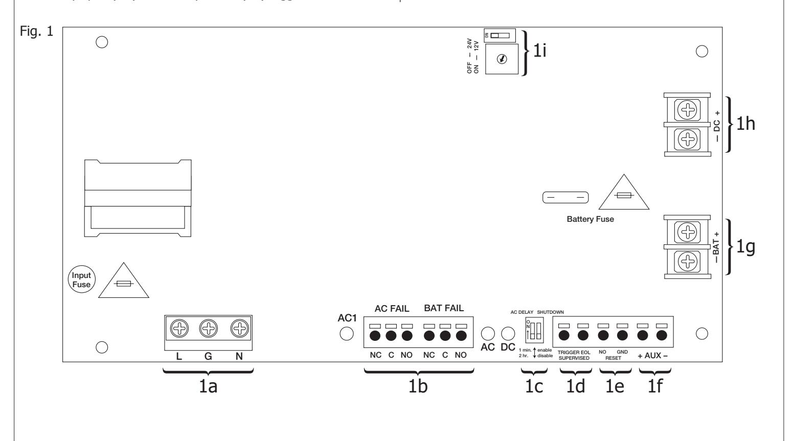
- 3. Set desired DC output voltage by setting SW1 to the appropriate position on the power supply board (Fig. 1i, pg. 1).
- 4. Connect unswitched AC power (120VAC 60Hz) to terminals marked [L, G, N] (Fig. 1a, pg. 1). Use 14 AWG or larger for all power connections. Secure green wire lead to earth ground.
Keep power-limited wiring separate from non power-limited wiring (120VAC 60Hz Input, DC Output (refer to Specifications chart pg. 1) , Battery Wires). Minimum 0.25" spacing must be provided.
CAUTION: Do not touch exposed metal parts.
Shut branch circuit power before installing or servicing equipment.
There are no user serviceable parts inside. Refer installation and servicing to qualified service personnel.
- 5. Measure output voltage before connecting devices. This helps avoiding potential damage.
- 6. Connect devices to be powered to terminals marked [– DC +] (Fig. 1h, pg. 1). For auxiliary device connection this output will not be affected by Low Power Disconnect or Fire Alarm Interface. Connect device to terminals marked [+ AUX –] (Fig. 1f, pg. 1).
- 7. For Access Control applications batteries are optional. When batteries are not used, a loss of AC will result in the loss of output voltage. When the use of stand-by batteries is desired, they must be lead acid or gel type. Connect battery to terminals marked [– BAT +] (Fig. 1g, pg. 1). Use two (2) 12VDC batteries connected in series for 24VDC operation (battery leads included). Use batteries - Casil CL1270 (12V/7AH), CL12120 (12V/12AH), CL12400 (12V/40AH), CL12650 (12V/65AH) batteries or UL recognized BAZR2 batteries of an appropriate rating.
Note: Separate enclosure must be used for housing 40AH or 65AH batteries.
- 8. Connect appropriate signaling notification devices to AC FAIL & BAT FAIL (Fig. 1b, pg. 1) supervisory relay outputs.
- 9. To delay AC reporting for 2 hrs., set SW2 to appropriate DIP switch position [AC Delay] (Fig. 1c, pg. 1).
- 10. To enable or disable Low Output Power Shutdown set SW2 to appropriate DIP switch position [Shutdown] (Fig. 1c, pg. 1).
- 11. A short or NO or NC input triggers FACP [Trigger EOL Shutdown] (Fig. 1d, pg. 1).
- 12. Place a jumper for non-latching FACP. A momentary short on these terminals resets FACP latching [Trigger EOL Shutdown] (Fig. 1e, pg. 1).
Wiring:
Use 18 AWG or larger for all low voltage power connections.
Note: Take care to keep power-limited circuits separate from non power-limited wiring (120VAC, Battery)
Maintenance:
Unit should be tested at least once a year for the proper operation as follows:
Output Voltage Test: Under normal load conditions, the DC output voltage should be checked for proper voltage level.
Battery Test: Under normal load conditions check that the battery is fully charged, check specified voltage (12VDC @ 13.2
or 24VDC @ 26.4) both at the battery terminal and at the board terminals marked [– BAT +] to ensure that
there is no break in the battery connection wires.
Replacing Batteries: Disconnect existing batteries. Connect battery to the terminals marked [– BAT +].
Use two (2) 12VDC batteries connected in series for 24VDC operation.
LED Diagnostics:
| Red (DC) | Green (AC) | Power Supply Status | |
|---|---|---|---|
| ON | ON | Normal operating condition. | |
| ON | OFF | Loss of AC. Stand-by battery supplying power. | |
| OFF | ON | No DC output. | |
| OFF | OFF | Loss of AC. Discharged or no stand-by battery. No DC output. | |
HS4 POWER SUPPLY/CHARGERS Installation Instructions I-EA00278
| Terminal Identification: | ||||
|---|---|---|---|---|
| Terminal Legend | Function/Description | |||
| L, G, N | Connect 120VAC 60Hz to these terminals: L to hot, N to neutral, G to ground (non power-limited) (Fig. 1a, pg. 1). | |||
| – DC + |
2-679-0994: 12VDC or 24VDC @ 6A continuous output (Non Power-Limited output).
2-679-0996: 12VDC @ 10A continuous output (Non Power-Limited output). 2-679-0995: 24VDC @ 10A continuous output (Non Power-Limited output). |
|||
| Trigger EOL Supervised |
Fire Alarm Interface trigger input from a short or FACP. Trigger inputs can be normally open,
normally closed from an FACP output circuit (Power-Limited input) (Fig. 1d, pg. 1). |
|||
| NO, GND - RESET | FACP interface latching or non-latching (Power-Limited) (Fig. 1c, pg. 1). | |||
| + AUX – | Auxiliary Power-Limited output rated @ 1A (unswitched) (Power-Limited output) (Fig. 1f, pg. 1). | |||
|
AC Fail
NC, C, NO |
Indicates loss of AC power, e.g. connect to audible device or alarm panel. Relay normally energized when
AC power is present. Contact rating 1A @ 30VDC (Power-Limited) (Fig. 1b, pg. 1). |
|||
|
Bat Fail
NC, C, NO |
Indicates low battery condition, e.g. connect to alarm panel. Relay normally energized when DC power is
present. Contact rating 1A @ 30VDC. A removed battery is reported within 5 minutes. Battery reconnection is reported within 1 minute (Power-Limited) (Fig. 1b, pg. 1). |
|||
| – BAT + | Stand-by battery connections. Maximum charge current 1.54A (non power-limited) (Fig. 1g, pg. 1). | |||
Stand-by Specifications:
| Battery | Access Control Applications Stand-by | |||||
|---|---|---|---|---|---|---|
| 2-679-0994 | 2-679-0996 | 2-679-0995 | ||||
| 7AH | 10 Mins./6A | 5 Mins./10A | 5 Mins./10A | |||
| 12AH | 35 Mins./6A | 15 Mins./10A | 15 Mins./10A | |||
| 40AH | Over 4 Hours/6A | Over 2 Hours/10A | Over 2 Hours/10A | |||
| 65AH | Over 4 Hours/6A | Over 4 Hours/10A | Over 4 Hours/10A | |||

HS4 POWER SUPPLY/CHARGERS Installation Instructions I-EA00278
| Notes: |
|---|
| nstalling Company: Service Rep. Name: |
| Address: Phone #: |