HS4 Control Units CU42xx Installation Instructions – 224901
Open the original PDF document
View PDFXS4 Controller

Installation guide Eng
- E Guía de instalación
- Guide d'installation F
The door controller reads the encrypted data contained on the carrier and allows for updating of the carrier via SALTO Virtual Network technology, making it possible to cancel lost or stolen cards remotely. It is equipped with input connections that permit third party readers integration.
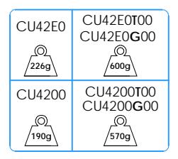
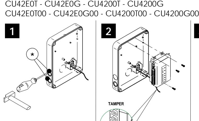
CU42E0T - CU42E0G - CU4200T - CU4200G
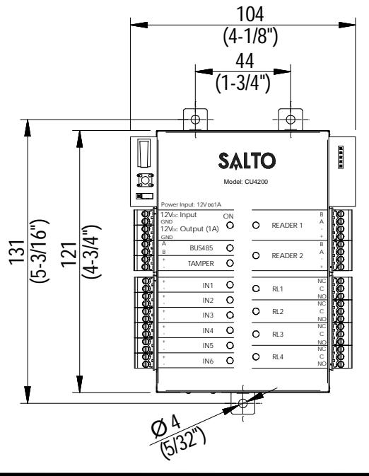
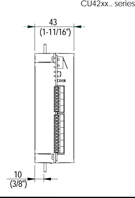
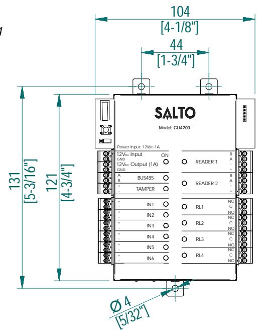
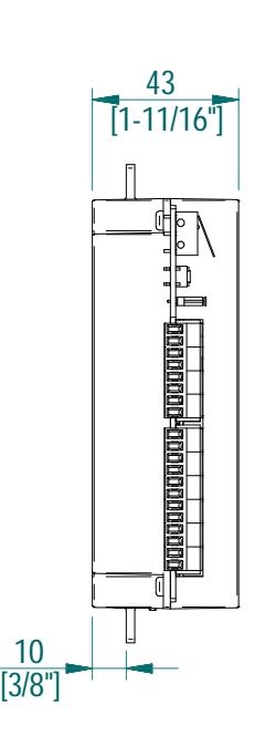
Mechanical Installation Eng E Instalación mecánica F Installation mécanique
CU42E0T00 - CU42E0G00 - CU4200T00 - CU4200G00 *
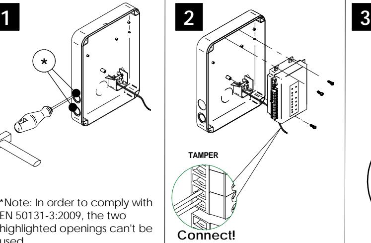
* Note: In order to comply with EN 50131-3:2009, the two highlighted openings can't be used.
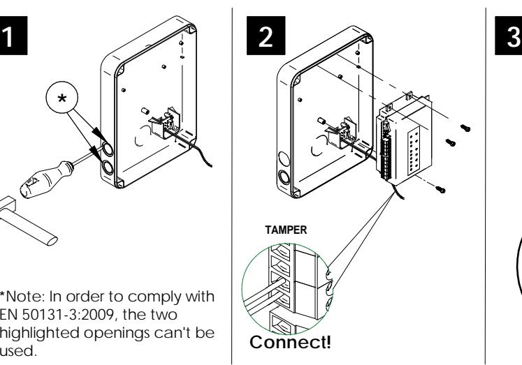
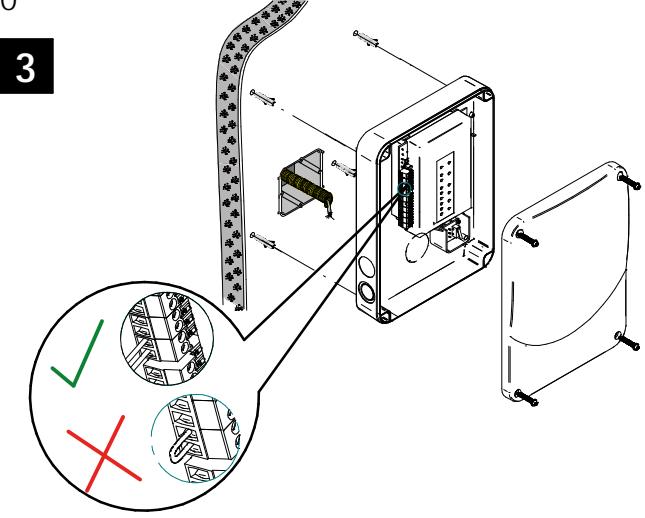
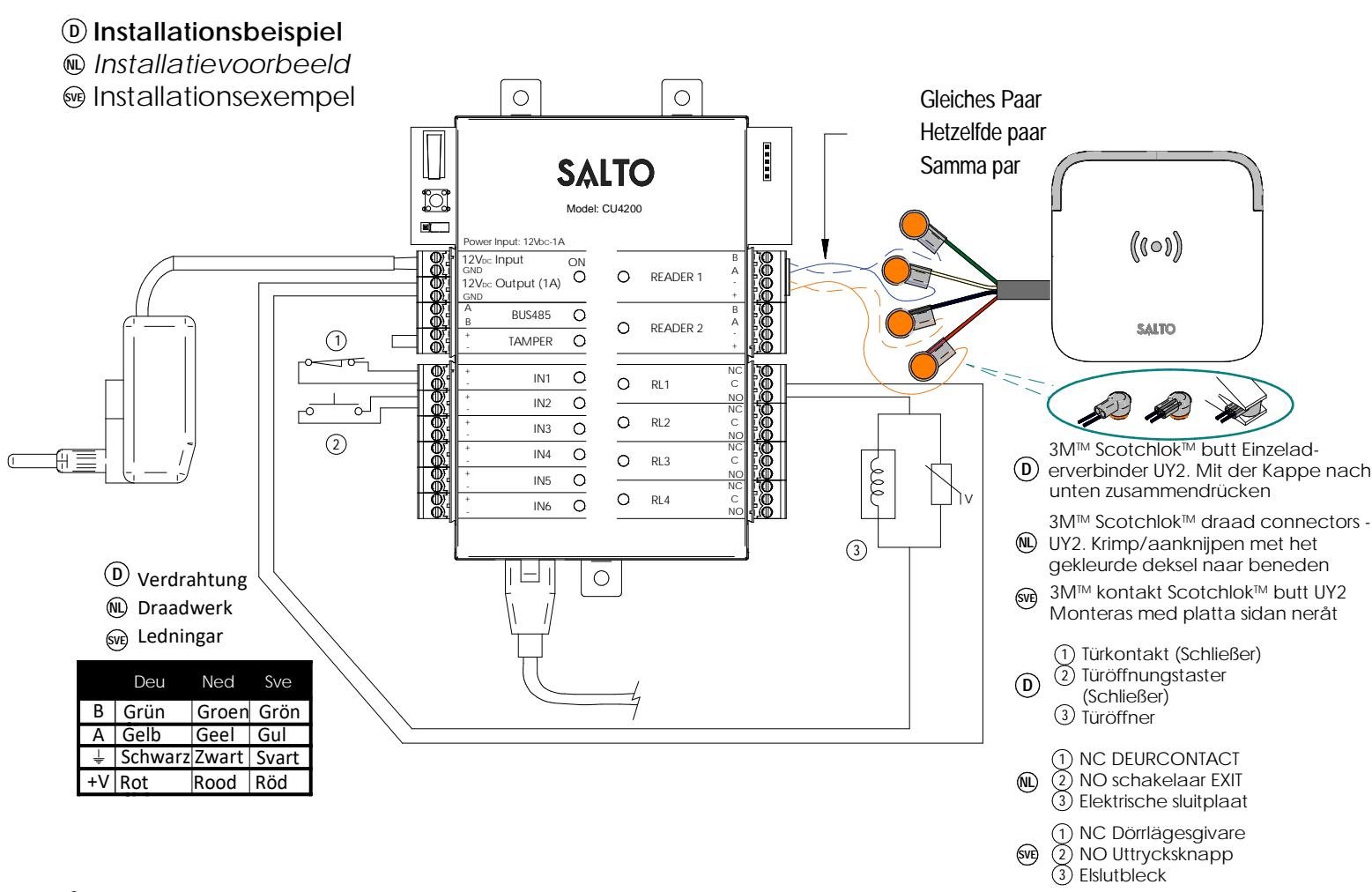
Note: Follow the same connection model, using the CU tamper input, when using a third party electric box equipped with a tamper opening detection.
XS4 Controller
Eng

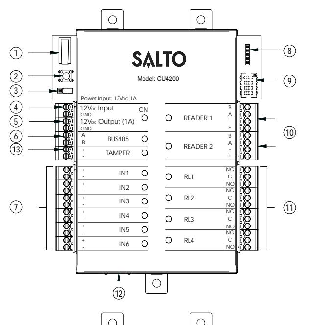
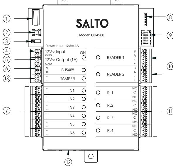
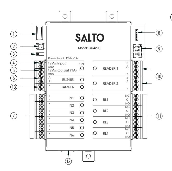
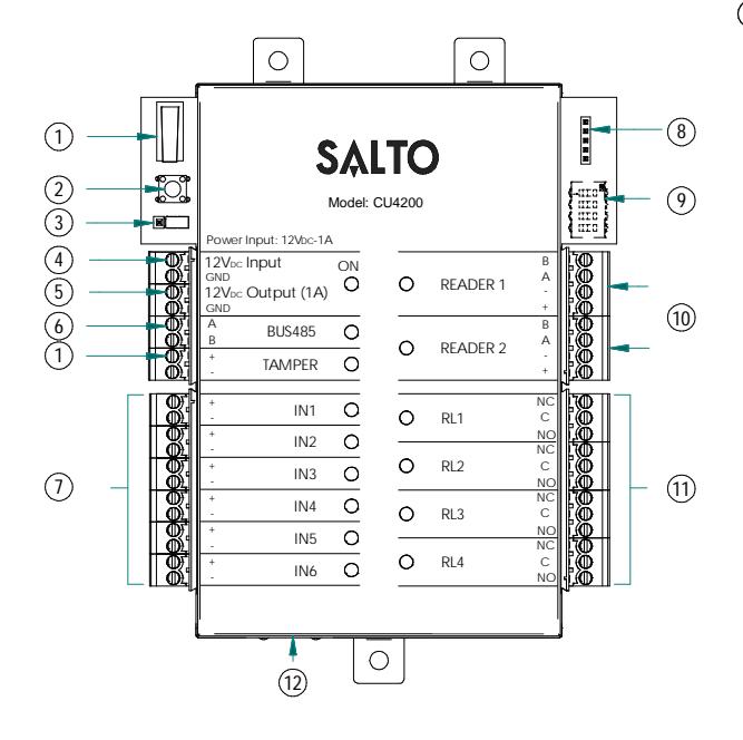
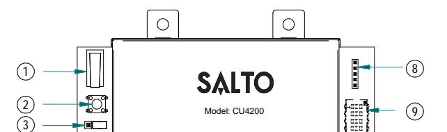
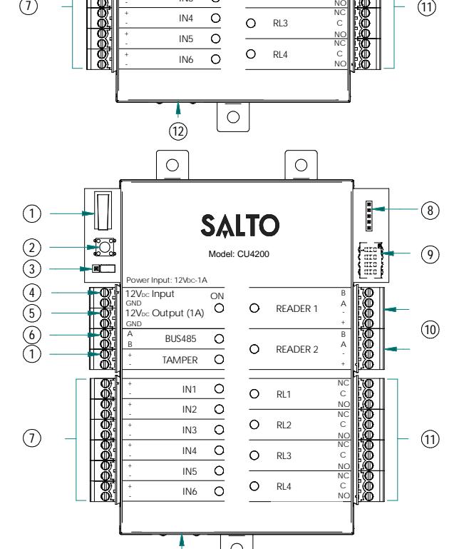
- 1 Physical tamper switch to be operated by external electric box models.
- 2 Clear button must be pushed (not more than 5 seconds) if the configuration has been changed, (i.e. reader added, connected by Ethernet, device connected by BUS485) and the tamper alarm must be activated by removing the tamper switch connector.
- 3 BUS RS485 Terminal resistor must be in the ON position when the CU is connected at the end of the BUS.
- 4 Power input.
- Power output: this output is directly connected to the power input port protected by a 1A fuse.
- 6 BUS485.
- 7 Inputs : installer must identify the bridge cable needed depending on the input configuration.
- 8 PPD Connection.
- 9 Address configure (Only CU4200) All connected CU addresses must be different from each other.
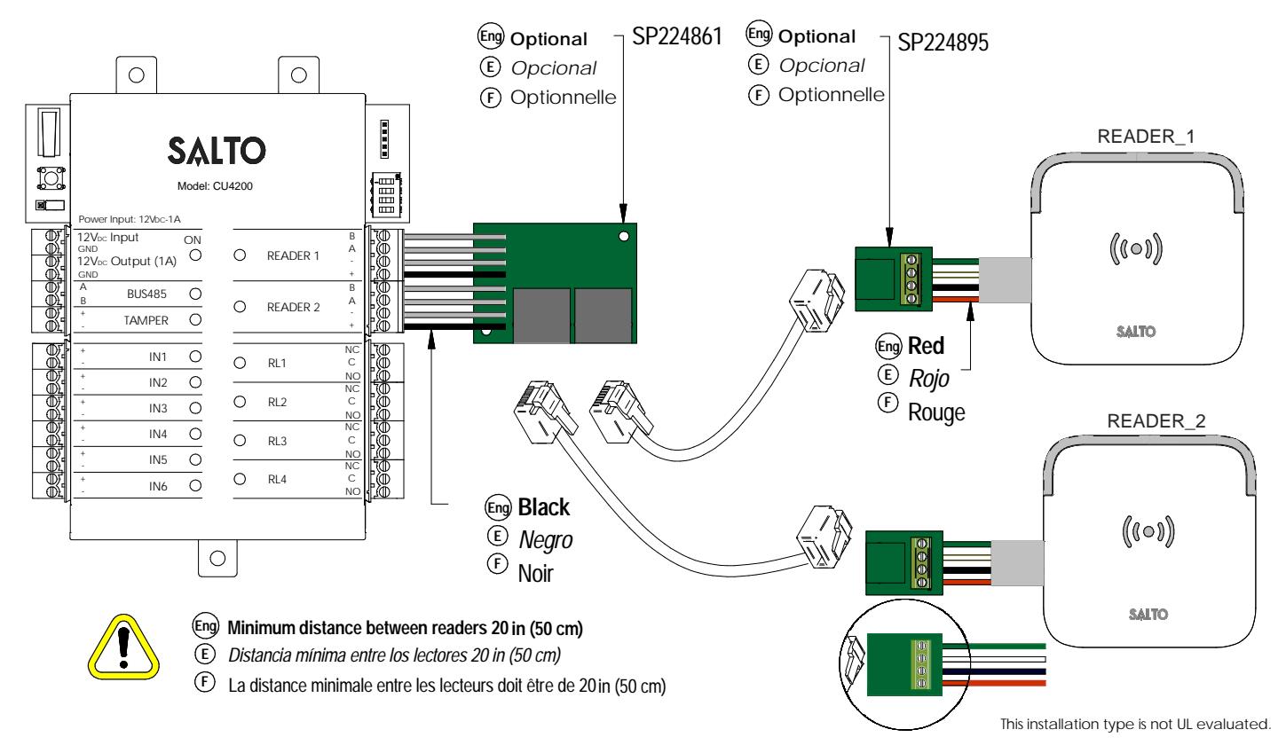
- Connection to readers: check reader installation manual to see recommended cable, connections and max. distances.
- 11 Relay connections: please take into account the max. load restrictions (2A-30VDC). Use the provided varistor if an inductive load is used.
- Ethernet connection (only CU42E0).
- Tamper input to connect the tamper signal from the SALTO electric box or other compatible devices.
-
E Tamper switch,
conectado en paralelo a la entrada del tamper. 1
- Clear button ha de ser pulsado (menos de 5 segundos), si se cambia la configuración: lector añadido, conectado por Ethernet, dispositivo conectado por BUS485 etc. Para ello, la alarma de tamper ha de estar activada (quitar el conector del tamper input). 2
- Resistor del terminal BUS RS485 requerido (posición ON) cuando la CU está conectada al final del BUS.
- Entrada de alimentación. 4
- Salida alimentada: esta salida se conecta directamente a la entrada de alimentación protegida por un fusible de 1 A. 5
- BUS485. 6
- Entradas : el instalador ha de identificar el cable para el puente dependiendo de la configuración de la entrada. 7
- Conexión para el PPD. 8
- Configurador del direccionador (Solo CU4200) Todos los direccionamientos de las distintas CUs han de ser diferentes. 9
- Conexión al lector. Consultar el manual de instalación del lector para ver el tipo de cable recomendado, conexionado y distancias máximas.
- Conexión al Relé: Tener en cuenta las restricciones de las cargas máximas (2ª-30VDC). Utilizar el varistor suministrado si la carga es inductiva.
- Contacteur anti subotage monté en parallèle avec l'entrée anti sabotaje.
- Bouton Clear doit être appuyé (pendant au moins 5 secondes) lorsque la configuration est modifée (ex: ajout d'un lecteur, connexion d'un cordon Ethernet, ajout d'un dispositive sur le BUS485) l'alarmeanti sabotage doit être active en enlevant le cavalier du bornier. 2
- La résistance de fin de bus RS485 est nécessaire (position ON) lorsque la CU est positionn'ee à l'extrémité du bus. 3
- Puissance d'entrée. 4
- Puissance de sortie: Cette sortie est reliéedirectement au port d' entrée de l'alimentation protégee par un fusible de 1 A. 5
- BUS485. 6
F
- Inputs: L'installateur doit identifier le cable necessaire en function de la configuration d'entrée.
- Connexion pour le PPD. 8
- Configuration de l'adresses (Uniquement pour CU4200) Les addresses des CU connectées au même BUS doivent être toutes différentes. 9
- Connexion des lecteurs: Consultez le manuel d'installation du lecteur afin de voir les câbles recommandés, les connexions et les distances maximales.
- Connexion des relais: S'il vous plaît prendre en compte les restrictions de charge max. (2ª-30VDC). Utilisez les varistances fournis si une charge inductive est utilisée (24v AC/DC Max). 11
- Connexion Ethernet (uniquement CU42E0).
XS4 Controller


| Factory cor | nfiguration | |
|---|---|---|
| IN1 | DOOR state for DOOR1 | unsupervised NC |
| IN2 | RTE input for DOOR1 | unsupervised NO |
| IN3 | DOOR state for DOOR2 | unsupervised NC |
| IN4 | RTE input for DOOR2 | unsupervised NO |
| IN5 | Office input for DOOR1 | unsupervised NO |
| IN6 | Office input for DOOR2 | unsupervised NO |
| RL1 | Lock Relay for DOOR1 | |
| RL2 | Tamper Alarm, DLO and intrusion DOOR 1 | |
| RL3 | Lock Relay for DOOR2 | |
| RL4 | Tamper Alarm, DLO and intrusion DOOR 2 |
| (E) | Configuraci | ón de fábrica | |
|---|---|---|---|
| IN1 | Estado de puerta PUERTA 1 | unsupervised NC | |
| IN2 | Input PULSADOR salida PUERTA 1 | unsupervised NO | |
| IN3 | Estado de puerta PUERTA 2 | unsupervised NC | |
| IN4 | Input PULSADOR salida PUERTA 2 | unsupervised NO | |
| IN5 | Input modo OFFICE PUERTA 1 | unsupervised NO | |
| IN6 | Input modo OFFICE PUERTA 2 | unsupervised NO | |
| RL1 | Relé PUERTA 1 | ||
| RL2 | Alarmas de Tamper, DLO e intrusión de PUERTA 1 | ||
| RL3 | Relé PUERTA 2 | ||
| RL4 | Alarmas de Tamper, DLO e intrusión de PUERTA 2 |
F État de porte pour la PORTE 1 non supervisé NC outon noussoir nour la PORTE 1 non supervisé NO IN3 État de norte nour la PORTE 2 non supervisé NC IN4 non supervisé NO outon poussoir pour la PORTE 2 IN5 Fonction office pour la PORTE 1 non supervisé NO IN6 onction office pour la PORTE 2 non supervisé NO RL1 Relais de commande pour la PORTE 1 RI2 Alarme sabotage, intruision ou porte ouverte PORTE 1
Alarme sabotage, intruision ou porte ouverte PORTE 2
Note: in order to comply with EN 60839-11:2013, the Enforce password policy must be enabled.
input connections
RI4
(Input supervision has not been evaluated by UL) CUADAP or third partie readers
| Wiegand | Omron | RS232 | |
|---|---|---|---|
| IN3 | D0 output | Clock output | |
| IN4 | D1 output | Data output | TX output |
| IN5 | D0 output | Clock output | |
| IN6 | D1 output | Data output | TX output |
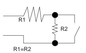
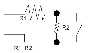
Supervised input connections
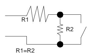
The resistance value R1 and R2 are defined in the software: 1k (recommended), 1k5, 2k2, 3k3, 4k7 6k8, 10k
© Conexión de las entradas
CUADAP o lectores de terceros
| Wiegand | Omron | RS232 | |
|---|---|---|---|
| IN3 | Salida D0 | Salida reloj | |
| IN4 | Salida D1 | Salida Datos | Salida TX |
| IN5 | Salida D0 | Salida reloj | |
| IN6 | Salida D1 | Salida Datos | Salida TX |
Conexión de las entradas supervisadas
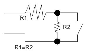
El valor de resistencia R1 y R2 se define en el Software: 1k (recomendado) ,1k5 ,2k2 ,3k3, 4k7, 6k8, 10k
© Connexion d'entrée
CUADAPT ou lecteur tiers.
| Wiegand | Omron | RS232 | |
|---|---|---|---|
| IN3 | Sortie D0 | Sortie Clock | |
| IN4 | Sortie D1 | Sortie Data | Sortie TX |
| IN5 | Sortie D0 | Sortie Clock | |
| IN6 | Sortie D1 | Sortie Data | Sortie TX |
Connexion d'entrée supervisée.
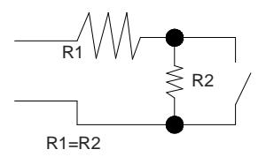
La valeur des résistances R1 et R2 sont définies dans le logiciel: 1k (recommandé), 1k5, 2k2, 3k3, 4k7, 6k8, 10k.
XS4 Controller

Electrical characteristics: Eng
Operation conditions
| Min | Typ | Max | Unit | |
|---|---|---|---|---|
| Temperature | 0 | 25 | 60 | ºC |
| Humidity | 35 | 85 |
Power
| Min | Nom. | Max | Unit | |
|---|---|---|---|---|
| InputVoltage | 12 | V | ||
| Current | 2Note1 | A | ||
| consumption | ||||
| Outputport | 1 | A | ||
| currentNote2 | ||||
| Reader Output Voltage | 12 | V |
Input
| Electrical | 5v Note3 |
| characteristics | |
| Configuration | ViaSoftware Note4 |
Cablerecommendation
| EthernetNote5 | UTP CAT5e |
| BUS485 | Twisted pair |
| Inputs | AWG24 |
| Readers | AWG18 |
Outputrelays
|
Ratedload(resistive)
2A‐30Vdc |
|---|
Note 1: This is consumption of the CU with 2 WR and using the output power port. The CU alone consumes 400mA. Depending on the installation installer must calculate the Power Supply needed.
Note 2: Same voltage as the input.
Note 3: 1K pull‐up resistor.
Note 4: See the software User Manual. Note 5: When Ethernet is available
E Características eléctricas
Condiciones ambientales
| Min | Typ | Max | Unit | |
|---|---|---|---|---|
| Temperatura | 0 | 25 | 60 | ºC |
| Humedad | 35 | 85 |
Potencia
| Min | Nom. | Max | Unit | |
|---|---|---|---|---|
| Voltage | 12 | V | ||
| Consumo de | 2 Nota 1 | A | ||
| la corriente | ||||
|
Output
CorrienteNota 2 |
1 | A |
Entrada
|
Características
Electricas |
5v Nota 3 |
|---|---|
| Configuración | ViaSoftwareNota 4 |
Cable recomendado
| EthernetNota 5 | UTP CAT5e |
| BUS485 | Pares trenzados |
| Inputs | AWG24 |
| Lectores | AWG18 |
Salida relés
| Carga (resistiva) | 2A‐30Vdc |
|---|---|
| Nota 1: consumo de la CU con 2 lectores | |
| y utilizando la salida alimentada. La CU | |
| consume 400mA. Dependiendo de la | |
| instalación, el instalador tiene que | |
| calcular la alimentación a utilizar. |
Nota 2: mismo voltage que la salida.
Nota 3: resistor de 1K.
Nota 4: consultar el manual de usuario.
Nota 5: cuando ethernet disponible.
Caractéristique électronique F
Condition de fonctionnement
| Min | Typ | Max | Unité | |
|---|---|---|---|---|
| Température | 0 | 25 | 60 | ºC |
| Humidité | 35 | 85 | ||
Puissance
| Min | Nom. | Max | Unité | |
|---|---|---|---|---|
| Tension d'entrée | 12 | V | ||
| Courant | 2 Note1 | A | ||
| de consommation | ||||
| Courant en sortie | 1 | A | ||
| du bornier | Note2 |
Entrée
| Caractéristique | 5v Note3 |
| électrique | |
| Configuration | Via Logiciel Note4 |
Type de câble
| EthernetNote5 | UTP CAT5e |
| Bus d'extension | Paire torsadée |
| Inputs | AWG24 |
| Lecteurs | AWG18 |
Relais de sortie
Charge nominal (résistive) 2A‐30Vdc
Note 1: Ceci est la consommation de la CU avec 2 lecteurs et utilisant le bornier de puissance de sortie. La CU à elle seule consome 400mA. Dépendant de l'installataion, l'installateur doit calculer l'alimentation nécessaire.
Note 2: Même tension que l'entrée
Note 3: Résistance de pull‐up 1K
Note 4: Consultez le manuel du logiciel utilisateur
Note 5: Si connectique Ethernet
UL Statements
Comply with ULC-S319 Class I:
This device complies with Industry Canada license-exempt RSS standard(s). Operation is subject to the following two conditions: (1) this device may not cause harmful interference, and (2) this device must accept any interference received, including interference that may cause undesired operation. Changes or modifications not expressly approved by the party responsible for compliance could void the user's authority to operate the equipment.
Le présent appareil est conforme aux CNR d'Industrie Canada applicables aux appareils radio exempts de licence. L'exploitation est autorisée aux deux conditions suivantes: (1) l'appareil ne doit pas roduire de brouillage, et (2) l'utilisateur de l'appareil doit accepter tout brouillage radioélectrique subi, même si le brouillage est susceptible d'en compromettre le fonctionnement.
This device has been tested and found to comply with the limits for a Class B digital device, pursuant to ICES-003.
XS4 Controller

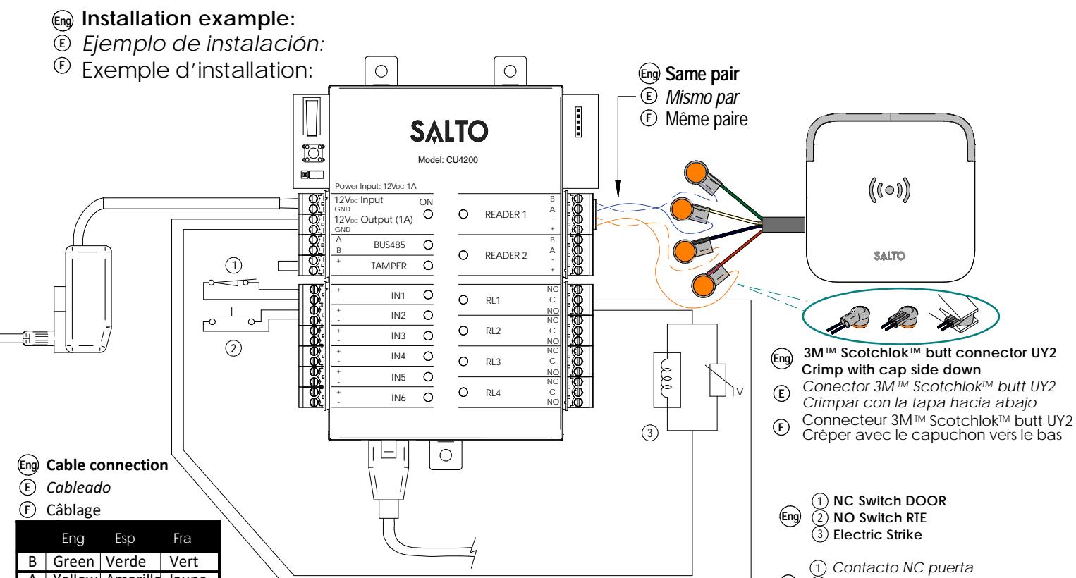
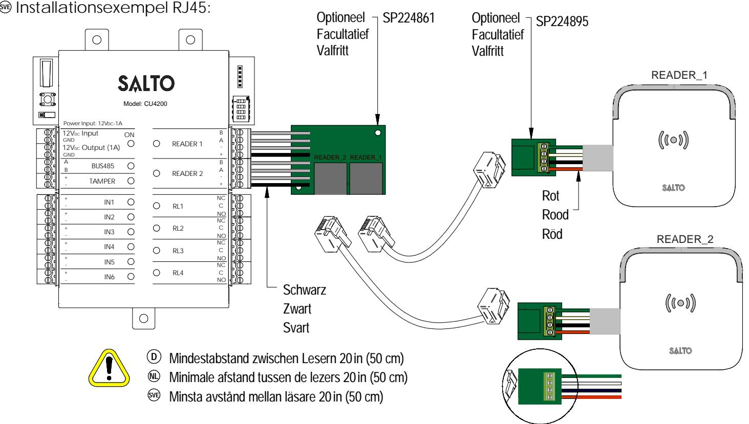
- installation example with RJ45:
- © Ejemplo de instalación RJ45:
Black
+V Red
Negro
Rojo
© Exemple d'installation avec connecteur RJ45 :
Contacto NO RTE Cerradero eléctrico
1) Etat de la porte NC (2) Bouton poussoir NO ③ Gâche électrique
(E)
XS4 Controller

Configuration: Eng
- 1. Prepare all the network connections (including Ethernet cable) setting up the dip-switch of each CU4200. Generate a tamper alarm by opening the CU housing or removing the tamper switch cable and then press the CLR button to detect all the connected readers. Check that the readers LEDs are ON (READER 1, READER 2).
- 2. Perform the set up in the software (Consult SALTO ProAccess SPACE user guide). Set up all the CU4200s with their dip-switches and assign the IP address to the CU42E0.
- 3. Adress the CU42E0:
- 3.1. Press the CLR BUTTON (CU42E0) to detect the readers and the connected CU4200. Check that the reader's LEDs blink and the BUS485 LEDs are switched ON.
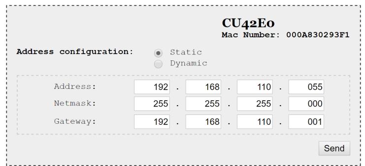
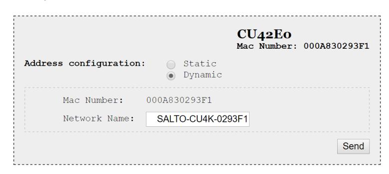
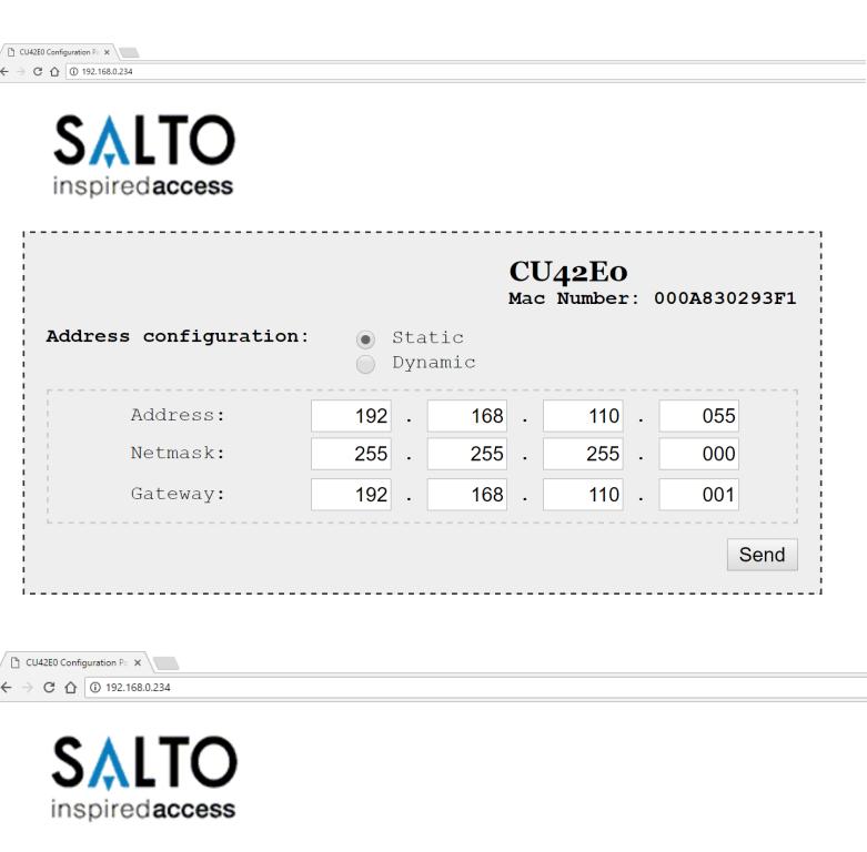
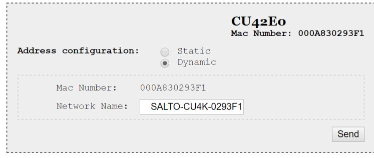
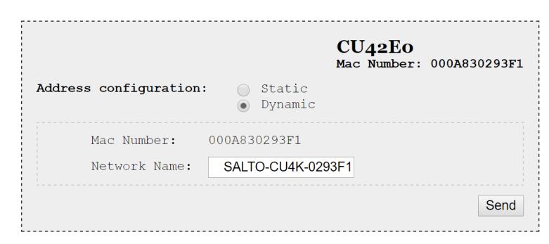
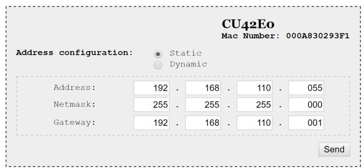
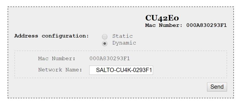
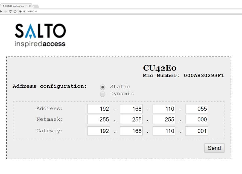
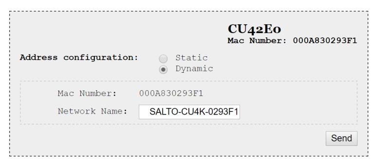
- 3.2. The CU42E0 is a DHCP ready device. If there's no DCHP server, the user can manually set up a static IP address using a web browser.
- 3.2.1. Press the CLR button for 5 seconds to access the addressing mode (LED ON will blink orange).
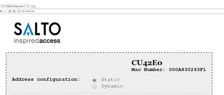
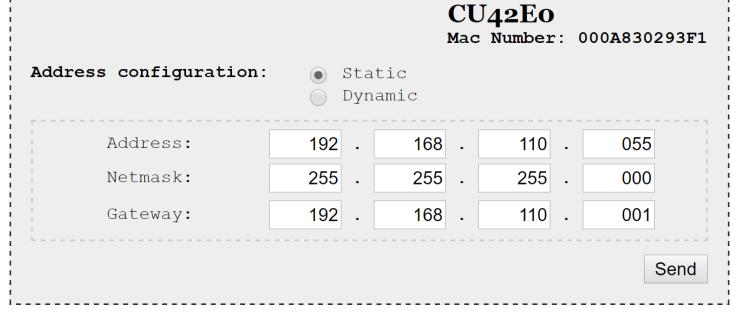
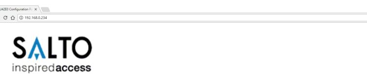
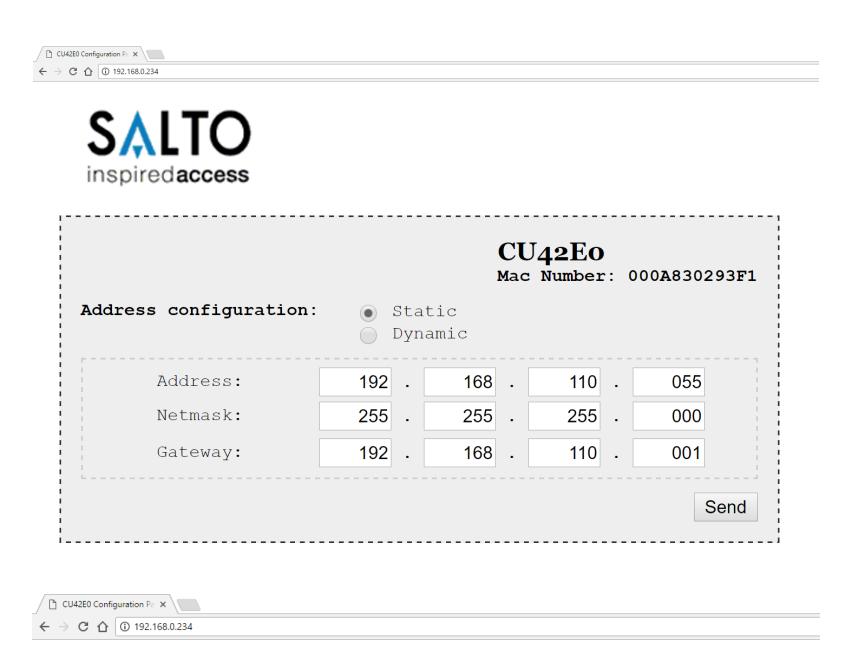
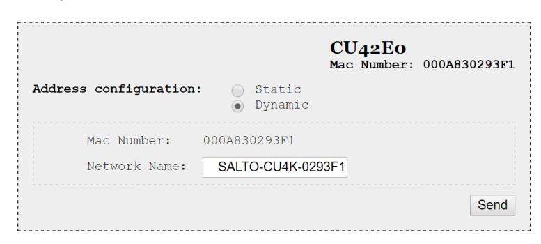
- 3.2.2. Access the IP address 192.168.0.234 with your web browser. Set up the network parameters and click on "send".
- 3.2.3. The CU42E0 will leave the addressing mode automatically, but you can also leave the addressing mode manually by pressing the CLR button for 5 seconds.
- 4. Use SALTO ProAccess software to detect the device (consult SALTO ProAccess Software user manual).


XS4 Controller

E Configuración:
- 1. Hacer todas las conexiones físicas de la red (incluido el cable Ethernet), configurando el dip-switch de cada CU4200. Crear una alarma de tamper. Para ello, abrir la caha o desconectar cable nulo de la entrada tamper y pulsar brevemente el botón de CLR para detectar los lectores conectados. Comprobar que los LEDs de los lectores están encendidos (READER 1, READER 2).
- 2. Crear configuración de la red en el Software (consultar el manual de usuario de usuario de SALTRO ProAccess SPACE).
- 3. Direccionar la CU42E0:
- 3.1. Pulsación corta del CLR (en la CU42E0) para detectar los lectores y CU4200 conectados.Comprobar que los LEDs de los lectores y el BUS485 están encendidos.
- 3.2. La CU42E0 es un dispositivo DHCP ready. Pero el usuario (si no hay servidor DHCP en su instalación) puede configurar manualmente una IP estática usando un navegador de Internet.
- 3.2.1. Pulsar durante 5 segundos el botón de CLR para entrar en el modo addressing (LED ON parpadeando en naranja).
- 3.2.2. Acceder a la dirección IP 192.168.0234 con un explorador estándar. Configurar los parámetros de red y pulsar el botón 'send' en cualquier momento (sin guardar los cambios) pulsando el botón de CLR durante 5 segundos.
- 4. Usar el Software de SALTO para detectar el dispositivo consultar el manual de usuario de SALTO ProAccess Software).


XS4 Controller

Configuration: F
- 1. Préparez toutes les connexions réseau (câble ethernet compris), paramétrez les micro-interrupteurs de chaque CU4200. Générez une alarme Tamper en ouvrant le boitier de la CU ou en déconnectant le cavalier Tamper et appuyez sur le bouton CLR pour détecter tous les lecterus connectés. Vérifiez que les LEDs des lecteurs son allumées (READER 1 et READER 2).
- 2. Définir la configuration dans le logiciel (Consultez le mode d'emploi ProAccess SPACE SALTO). Configurer toutes les CU4200s en fonction des Dipswitchs et attribuer l'adresse IP à la CU42E0.
- 3. Adresser la CU42E0:
- 3.1. Appuyer sur la touche CLR (CU42E0) pour détecter les lecteurs et les CU4200 connectées. Vérifier que les voyants des lecteurs clignotent et que les voyants du BUS485 sont allumés.
- 3.2. Le CU42E0 est un appareil livré en DHCP. Si il n'y a pas de serveur DHCP, l'utilisateur peut configurer manuellement une addresse IP statique à l'aide d'un navigateur Web.
- 3.2.1. Appuyer sur le buton CLR pendant 5 seconds pour accéder au mode d'adressage (LED ON clignote en orange).
- 3.2.2. Acc'eder à l'adresse IP 192.168.0.234 avec votre navigateur web. Mettre en place les paramètres réseau et cliquer sur 'send'.
- 3.2.3. Le CU42E0 va quitter le mode d'adressage automatiquement, il est toutefois possible d'arrêter le mode d'adressage sans enregistrer la modification en appuyant sur la touche CLR 5 secondes.
- 4. Utiliser un logiciel ProAccess SALTO pour détecter les périphériques (consultez du logiciel ProAccess SALTO).


XS4 Controller

Dipswitch set up: Eng
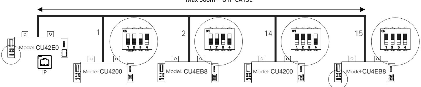
When CU4200 is used offline, the dip-switch setting has to be OFF for all 4 switches (0000). When connected to an online CU42E0 by BUS485, the CU4200 dip-switch setting is used to give each device on the BUS485 a unique address. Ensure that the address in the software is the same as the one you put on the hardware. (See Table). Both ends of the BUS485 must have the RS485 BUS termination resistor in the ON position, intermediate CU4200s need to have the resistor in OFF position.
Si la CU4200 está en modo offline, la configuración del dip-switch ha de estar en OFF con los 4 switches en off (0000). Configuración del dip-switch: E
Cuando la CU4200 está conectada a una CU42E0 ONLINE por BUS485, el dip-switch de la CU4200 se usa para asignarle una dirección dentro del BUS485. Esta dirección ha de ser detallada en el software. Ver tabla adjunta. Ambos extremos del BUS485 han de tener la resistencia del terminal en posición ON, y el resto de CU4200s han de tener este resistor en posición OFF.
| ADDRESS | |
|---|---|
| 0000 | Offline |
| 0001 | Address 1 |
| 0010 | Address 2 |
| 0011 | Address 3 |
| 0100 | Address 4 |
| 0101 | Address 5 |
| ADDRESS | |
|---|---|
| 0110 | Address 6 |
| 0111 | Address 7 |
| 1000 | Address 8 |
| 1001 | Address 9 |
| 1010 | Address 10 |
| 1011 | Address 11 |
| ADDRESS | |
|---|---|
| 1100 | Address 12 |
| 1101 | Address 13 |
| 1110 | Address 14 |
| 1111 | Address 15 |
Configuration du Dipswitch: F
Si la CU4200 est en mode déconnectée, les réglages du dipswitch doit être éteint avec le 4 switches en OFF (0000).
Lorsque la CU4200 est connectée à une CU42E0 ONLINE par BUS485, le dipswitch de la CU4200 est utilisé pour attribuer une adresse dans le BUS485. Cette adresse doit être détaillé dans le logiciel. Voir tableau ci-joint. les deux extrémités de BUS485 doivent avoir les résistances de fin de ligne en position ON, et le reste des CU4200 doivent avoir cette résistance hors tension.
Set up example: Eng
Same configuration at SALTOs ProAccess SPACE Software
- Ejemplo de configuración: Misma configuración que en el Software ProAccess SPACE de SALTO E
- Exemple de configuration: Même configuration que le logiciel SALTO ProAccess SPACE F
Max 300m ‐ UTP CAT5e
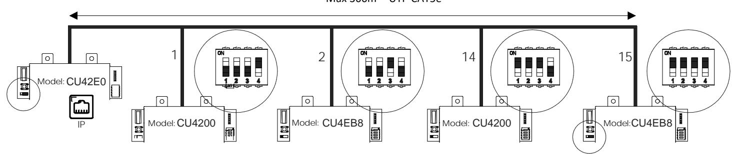
(The interconnection has not been evaluated by UL, the model CU4EB8 has not been evaluated by UL)
Maximum number of devices on BUS485: 16 units, with a maximum of 4 units CU4200 and 15 units CU4EB8. Eng
Número máximo de dispositivos en BUS485: 16 unidades, con un máximo de 4 unidades CU4200 y 15 unidades CU4EB8. E
Nombre maximum d'appareils sur un BUS485: 16 unités, avec un maximum de 4 unités CU4200 et 15 unités CU4EB8. F
XS4 Controller

Signaling: Eng
The LEDs in the top layer of the CU show the state of the system:
| LED name | Description |
|---|---|
| GREEN ON: the unit is powered correctly | |
| BLINKING RED: the unit is not powered properly (check power supply) | |
| ON | BLINKING ORANGE: addressing mode |
| OFF: not powered | |
| ON CU4200:The unit is communicating with the CU42E0 | |
| BUS485 | ON CU42E0: To be defined |
| OFF CU4200:The unit is not communicating with the CU42E0 (press the CLR to start detection process) | |
| OFF CU42E0: To be defined | |
| TAMPER | ON: tamper alarm active |
| OFF: tamper alarm not active | |
| IN1-IN6 | ON: active input (depends on the input type configured in the software) |
| OFF: inactive input (depends on the input type configured in the software) | |
| READER | ON: the reader is communicating with the CU |
| OFF: the reader is not communicating with the CU (press the CLR to start detection process) | |
| RL1-RL4 | ON: the relay is activated (NO is connected with C). |
| OFF: the relay is inactive (NC is connected with C). | |
Señalética: E
Los LEDs en la parte superior de la CU muestran el estado del sistema:
| Nombre del LED | Descripcióon |
|---|---|
| VERDE ON: el dispositivo está correctamente alimentado | |
| ROJO INTERMITENTE: el dispositivo no está correctamente alimentado (comprobar la fuente de alimentación) | |
| ON | NARANJA INTERMITENTE: modo direccionamiento |
| OFF: sin alimentación | |
| ON CU4200: El dispositivo se comunica con la CU42E0 | |
| BUS485 | ON CU42E0: Por definir. |
| OFF CU4200: el dispositivo no se comunica con la CU42E0 (presione el botón CLR para iniciar la detección) | |
| OFF CU42E0: Por definir. | |
| TAMPER | ON: alarma tamper activada |
| OFF: alarma tamper desactivada | |
| IN1-IN6 | ON: input activado (depende del tipo de input configurado a través del software) |
| OFF: input desactivado (depende del tipo de input configurado a través del software) | |
| READER | ON: el lector comunica con la CU |
| OFF: el lector no comunica con la CU (presione el botón CLR para iniciar la detección) | |
| RL1-RL4 | ON: relé activado (NO está conectado con C). |
| OFF: relé desactivado (NC está conectado con C). |
F Signalisation:
Les LEDS en façade avant de la CU indique l'état du système
| Nom LED | Description | |
|---|---|---|
| VERT : l'appareil est correctement alimenté | ||
| Rouge clignotant : l'appareil est mal alimenté (vérifier la tension d'alimentation) | ||
| ON | Orange clignotant : en mode adressage | |
| OFF: non alimenté | ||
| ON CU4200 :L'unité communique correctement avec la CU42E0 | ||
| BUS485 | ON CU42E0 : À définir. | |
| OFF CU4200 : L'unité ne communique pas avec la CU42E0 (appuyez sur le CLR pour lancer le processus de détection) | ||
| OFF CU42E0 : À définir. | ||
| TAMPER | ON : alarme active | |
| OFF : alarme désactivé | ||
| IN1-IN6 | ON : entrée active (dépend du type d'entrée configuré dans le logiciel) | |
| OFF : entrée inactive (dépend du type d'entrée configuré dans le logiciel) | ||
| READER | ON : le lecteur est en communication avec la CU | |
| OFF : le lecteur ne communique pas avec la CU (appuyez sur le CLR pour lancer le processus de détection) | ||
| RL1-RL4 | ON : le relais est actif (NO est connecté avec C) | |
| OFF : le relais est inactif (NC est relié à C) | ||
UL Statements
UL listed models are CU42E0G00, CU42E0T00, CU4200G00 and CU4200T00. Models CU42E0, CU4200, CU42E0G, CU42E0T, CU4200G, CU4200T and CU4EB8 are not UL listed.
The unit shall be supplied by UL294 and S319 listed external power supply with built-in secondary battery, whose output is Class 2, and rating is 12 VDC, minimum 2 A.
UL294 Performance level:
| Feature | Level |
|---|---|
| Destructive Attack | I |
| Line Security | I |
| Endurance | IV |
| Standby Power | Per rating of external listed P.S. |
Field wiring leads must be UL listed but the AWG should not be smaller than AWG26 and no bigger than AWG18. Maximum length of the cable for the readers is 400 m with AWG18 cable.
The interconnection between CU4200 and CU42E0, and between CU42E0 and PC are not UL evaluated.
The LAN connect cable shall locate in the same room, and is not permitted to be greater than 98.5 ft (30 m) long. Comply with ULC-S319 Class I.
EN 50131-3:2009 & EN 60839-11-1:2013 Statements
Certification issued by ALTER TECHNOLOGY TÜV NORD S.A.U. for the models: CU42E0T00, CU42E0G00, CU4200T00 and CU4200G00. Stationary ACE, Type B.
Performance level:
- Security Grade 2 (EN 50131-3:2009), Class II
- Grade 2 (EN60839-11-1:2013), Class II
- IK04
- 2^24 variations of supported credentials
- CU42E0 contains 3x EEPROM (512Kbits)/ CU4200 contains 2x EEPROM (512Kbits)
- The unit shall be supplied by a EN 50131-6:2017 certified external power supply or by the power output of another SALTO Control Unit.
XS4 Controller

CU42xx.. series
Installationsanleitung D
NL Installatiehandleiding
Installationsguide SVE
Mechanische installation Mechanische installatie Mekanisk installation D NL SVE
* Note: In order to comply with EN 50131-3:2009, the two highlighted openings can't be used.
Note: Follow the same connection model, using the CU tamper input, when using a third party electric box equipped with a tamper opening detection.
XS4 Controller


- 485 Bus Abschluss Wiederstände notwendig (ON Position) wenn die CU am Anfang oder Ende des Buses sitzt. 3
- Spannungseingang 4
- Spannunsausgang: Dieser Spannungsausgang ist dierekt mit dem Spannungseingang verbunden, jedoch durch eine 1A Sicherung abge-sichert. 5
- BUS485 6
- Eingänge: Bei der Installation müssen je nach Konfiguration eventuell Eingänge gebrückt werden. Der Steuerung liegen hierzu 3 Kabelbrücken für diesen Zweck bei 7
- PPD Verbindung 8
- Adresskonfiguration (Nur CU4200 ) Alle CU4200 im selben Bus, müssen unterschiedliche Adressen haben 9
- Verbindung für Leser: Für Anschluß und Entfernungen, bitte die Montag-eanleitung des Lesers beachten. 10
- Ausgangsrelais: Bitte beachten Sie die maximale Schaltleistung von 2A-30VDC. Nutzen Sie die beiliegenden Varisatoren, für Induktive Verbraucher (24v AC/DC max.) 11
- 12 Nethwerkverbindung (Nur CU42E0).
TAMPER IN1
BUS485
12VDC Input ON
12VDC Output (1A) Power Input: 12VDC-1A
4 5 6
1
IN3
READER 1
READER 2
NC NC NO
A
10
A
RL1 RL2
-
NL Sabotage schakelaar
is parallel verbonden met Sabotage ingang.
Clear button
moet ingedrukt worden (minder dan 5 sec) als configu-ratie is veranderd. Bijv. Lezer toegevoegd, Ethernet verbonden of een apparaat is toegevoegd aan BUS485, enz. De sabotagemelding (tamper) moet aanstaan 1 2
- om de configuratie te kunnen voltooien. RS485 Bus eindweerstand is nodig (ON positie) wanneer de CU aan het einde van de bus ligt. 3
- Voeding ingang 4
- Voeding uitgang: Deze output is direct verbonden met de power input poort beschermd door een 1A zekering. 5
- BUS485 6
- Ingangen: Installateur moet vaststellen welke kabel nodig is, afhankelijk van de input configuratie. Indien geen deursensoren of sabotagecon-tact gebruikt wordt, sluit de meegeleverde 3 kabelbruggen aan op deze ingangen. 7
- PPD Connectie 8
- Adres configuratie (Alleen CU4200) Alle CU4200 adressen verbonden met de RS485Bus moeten van elkaar verschillen. 9
- Lezer aansluitingen : Zie de installatie handleiding van de (wand)lezer voor de aanbevolen kabel, verbindingen en maximale afstanden.
- Relais aansluitingen: Houd alstublieft rekening met de maximale belasting (2A-30VDC). Gebruik de meegeleverde varistors als er een inductieve lading wordt gebruikt (24vC/DC max.) 11
- 12 Ethernet aansluiting (alleen bij de CU42E0)
-
Sabotage-kontakt
är ansluten parallellt med sabotageingång.
Resetknappen
måste tryckas ner (inte mer än 5 sekunder) om hårdvarukonfigurationen har ändrats (t.ex. en läsare är inkopplad, nätverkssladden har anslutits, osv.) samt så måste tamper-larmet aktiveras genom att koppla ur tamper-bygeln/kontakten. 1 2
SVE
- RS485 Buss-terminering krävs (position ON) om detta är den sista enheten i slingan.
- Power Input 4
- Ström utgång: Denna utgång är direkt kopplad till strömingången,
- BUS485 6
- Ingångar :Installatören måste identifiera vilka kablar som behövs, beroende på konfigurationen. Tre kablar medföljer vid leverans för detta ändamål. 7
- PPD Anslutning 8
- Adress-konfigurering (endast CU4200): Alla CU4200 anslutna via BUS485 måste ha olika adresser. 9
- Anslutning till läsare: Se väggläsarens manual för rekommendation kring kabeltyp, anslutning och avstånd.
- Reläanslutningar: V.g. notera max. belastningen (2A-30VDC). Använd medföljande Varistor vid behov. (24v AC/DC max.) 11
- 12 Nätverksanslutning (endast CU42E0)
XS4 Controller

(D)
| Werl | skonfiguration | |
|---|---|---|
| IN1 | Türkontakt Tür 1 | unüberwachter NC |
| IN2 | Türöffnungstaster Tür 1 | unüberwachter NO |
| IN3 | Türkontakt Tür 2 | unüberwachter NC |
| IN4 | Türöffnungstaster Tür 2 | unüberwachter NO |
| IN5 | Eingang für Office-Mode Tür 1 | unüberwachter NO |
| IN6 | Eingang für Office-Mode Tür 2 | unüberwachter NO |
| RL1 | Ausgangsrelais Tür 1 | |
| RL2 | Sabotagealaram, Tür zu lange offen und Einbruch Tür 1 | |
| RL3 | Ausgangsrelais Tür 2 | |
| RL4 | Sabotagealaram, Tür zu lange offen und Einbruch Tür 2 |
(NL)
| ) | Fabrieksinstellingen | ||||
|---|---|---|---|---|---|
| IN1 | Deurstatus voor DEUR1 | onbewaakt NC | |||
| IN2 | Req EXIT input voor DEUR1 | onbewaakt NO | |||
| IN3 | Deurstatus voor DEUR2 | onbewaakt NC | |||
| IN4 | Req EXIT input voor DEUR2 | onbewaakt NO | |||
| IN5 | Loopstand voor DEUR1 | onbewaakt NO | |||
| IN6 | Loopstand voor DEUR2 | onbewaakt NO | |||
| RL1 | Uitgangrelais voor DEUR1 | ||||
| RL2 | Sabotage alarm, Deur open laten staan, inbraak Deur1 | ||||
| RL3 | Uitgangrelais voor DEUR2 | ||||
| RL4 | Sabotage alarm, Deur open laten staan, inbraak Deur2 | ||||
SVE
| Fabrik | Fabriksinställning | ||||
|---|---|---|---|---|---|
| IN1 | DÖRRLÄGE för DOOR1 | Ej övervakad NC | |||
| IN2 | Jttrycksknapp för DOOR1 | Ej övervakad NO | |||
| IN3 | DÖRRLÄGE för DOOR2 | Ej övervakad NC | |||
| IN4 | Jttrycksknapp för DOOR2 | Ej övervakad NO | |||
| IN5 | KONTORSLÄGE för DOOR1 | Ej övervakad NO | |||
| IN6 | KONTORSLÄGE för DOOR2 | Ej övervakad NO | |||
| RL1 | åsrelä för DOOR1 | ||||
| RL2 | abotagelarm, Dörr lämnad öppen, Intrångsalarm DÖRR 1 | ||||
| RL3 | åsrelä för DOOR2 | ||||
| RL4 | abotagelarm, Dörr lämnad öppen, Intrångsalarm DÖRR 2 | ||||
(D) EINGANG Konfiguration
CUADAP oder Fremdleser
| Wiegand | Omron | RS232 | |
|---|---|---|---|
| IN3 | D0 Ausgang | Clock Ausga | ng |
| IN4 | D1 Ausgang | Data Ausgai | ngTX Ausgang |
| IN5 | D0 Ausgang | Clock Ausga | ng |
| IN6 | D1 Ausgang | Data Ausgai | ngTX Ausgang |
Überwachter Eingang
Die Widerständswert können via Software definiert werden: 1k5, 2k2, 3k3, 4k7, 6k8, 10k
Ingangen
CUADAP en lezers van derden
| Wiegand | Omron | RS232 | |
|---|---|---|---|
| IN3 | D0 uitgang | Clock uitgang | |
| IN4 | D1 uitgang | Data uitgang | TX uitgang |
| IN5 | D0 uitgang | Clock uitgang | |
| IN6 | D1 uitgang | Data uitgang | TX uitgang |
| _ |
Ingangen onder toezicht
De weerstandswaardes R1 en R2 zijn in te stellen in de software: 1k (aanbevolen), 1k5, 2k2, 3k3, 4k7, 6k8 of 10k
CUADAP eller 3e partsläsare
| Wiegand | Omron | RS232 | |
|---|---|---|---|
| IN3 | D0 utgång | Clock utgång | |
| IN4 | D1 utgång | Data utgång | TX utgång |
| IN5 | D0 utgång | Clock utgång | |
| IN6 | D1 utgång | Data utgång | TX utgång |
Övervakad ingång
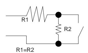
Motståndsvärdet R1 och R2 anges i mjukvaran:1k (rekommenderas), 1k5, 2k2, 3k3, 4k7 6k8, 10k
XS4 Controller

- Installationsbeispiel RJ45: D
- Installatie voorbeeld RJ45: NL
XS4 Controller

Elektronische Charakteristik: D
Umgebungsbedingungen
| Min | Typ | Max | Einheit | |
|---|---|---|---|---|
| Temperatur | 0 | 25 | 60 | ºC |
| Feuchtigkeit | 35 | 85 |
Spannung
| Min | Nom. | Max | Einheit |
|---|---|---|---|
| Eingangsspannung | 12 | V | |
| Stromverbrauch | 2 Note1 | A | |
| Steuerung | |||
| Max. Belastung | 1 | A | |
| Spannungsausgang Note2 |
Eingänge
| Max. Spannung | 5v Note3 |
|---|---|
| Konfiguration | ViaSoftwareNote4 |
Verkabelung
| EthernetNote5 | UTP CAT5e |
| Erweiterungs Bus | Twisted pair |
| Inputs | AWG24 |
| Leser | AWG18 |
Ausgangsrelais
| Zulässige Belastung | 2A‐30Vdc | |
|---|---|---|
| Note 1: Diese Angabe ist bei 2 angeschlossenen | ||
| Wandlesern und Verwendung des 12V Ausgangs. | ||
| Die Steuerung alleine verbraucht 400mA. |
Abhängig von den angeschlossenen Komponent‐ en muss der Installateur ein entsprechendes Netzteil berechnen und planen.
Note 2: Gleiche Spannung wie Eingang
Note 3: 1K Pull‐Up‐Wiederstand
Note 4: Bitte im Softwarehandbuch nachschlagen
Note 5: Wenn Netzwerk verfügbar ist
Technische gegevens: NL
Omgeving
| Min | Typ | Max | Eenheid | |
|---|---|---|---|---|
| Temperatuur | 0 | 25 | 60 | ºC |
| Vochtigheid | 35 | 85 |
Vermogen
| Min | Nom. | Max | Eenheid | |
|---|---|---|---|---|
| InputVoltage | 12 | V | ||
| Stroomverbruik | 2 opm1 | A | ||
| Stroom | 1 | A | ||
| uitgaandopm2 |
Input
| Electra | 5v opm3 |
| eigenschappen | |
| Configuratie | ViaSoftwareopm4 |
Kabel aanbeveling
| UTP CAT5e |
| Twisted pair |
| AWG24 |
| AWG18 |
Relaisuitgangen
| 2A‐30Vdc |
Opm 1: Dit verbruik is wanneer er 2 wandlezers aangesloten zijn op een CU en gebruik wordt gemaakt van de 12 V‐uitgang.De controller alleen verbruikt 400mA.Afhankelijk van de aangesloten componenten, moet de installateur een geschikte voeding berekenen en plaatsen.
Opm 2: Evenveel vermogen als ingevoerd door voeding.
Opm 3: 1K pull‐up weerstand.
Opm 4: Zie de Software gebruikershandleiding
Opm 5: Wanneer Ethernet beschikbaar is
Tekniska data:
Arbetsområde
| Min | Typ | Max | Enhet | |
|---|---|---|---|---|
| Temperatur | 0 | 25 | 60 | ºC |
| Fukt | 35 | 85 |
Ström
| Min | Nom. | Max | Enhet | |
| Spänning in | 12 | V | ||
| Strömför | 2Not 1 | A | ||
| ‐brukning | ||||
| Spänning | 1 | A | ||
|
ut
Not 2 |
Drift
| Spänning | 5v Not 3 |
|---|---|
| Konfiguration | Via MjukvaraNot 4 |
Kabel rekommendation
| Nätverk Not 5 | |
| Expansionsbuss | |
| Ingångar | |
| Läsare |
Reläutgångar
| Märkström (resistiv) | 2A‐30Vdc |
| Not. 1: Detta är strömförbrukningen för |
Kontrollboxen med 2 aktiva läsare samt den externa utgången aktiv. Kontrollboxen själv drar 400mA. Beroende på vad som ingår i installa‐ tionen måste installatören beräkna hur mycket strömförsörjningen måste kunna leverera. Not. 2: Samma volttal som kopplas in I
kontrollenheten
Not. 3: 1K PU motstånd. Not. 4: Se mjukvarumanual
Not. 5: När nätverk skall användas
XS4 Controller

D Konfiguration:
- 1. Bereiten Sie alle Netzwerkverbindungen vor (inkl. Patchkabel) und stellen alle DIP Schalter der CU4200 korrekt ein. Lösen Sie den Sabotage (Tamper) Alarm aus, so dass die LED rot leuchtet. Drücken Sie die CLR Taste einmal um alle angeschlossenen BUS Komponenten und Leser einzulernen. Prüfen Sie ob die LED's für Leser 1 und 2 leuchten.
- 2. Programmieren Sie alle Komponenten in der Software ProAccess SPACE, hierzu können Sie das Handbuch der Software zu rate ziehen.
- 3. Adressierung CU42E0:
- 3.1. Drücken Sie den "CLR" Taster einmal kurz, wenn der Sabotagekontakt offen ist. Die LED's müssen einmal kurz aufleuchten.
- 3.2. CU42E0 ist DHCP Vorbereitet. In Werksauslieferung ist der DHCP Modus aktiviert. Wenn der Kunde keinen DHCP Server verwendet, dann muss eine manuelle IP-Adresse konfiguriert werden.
- 3.2.1. Drücken Sie den "CLR" Button so lange, bis die Steuerung im Adressiermodus ist (ON LED blinkt orange). Wichtig vor dem Drücken des "CRL" Tasters muss der Sabotagekontakt offen sein.
- 3.2.2. Greifen Sie per Web-Browser auf die Standard IP-Adresse 192.168.0.234 der Steuerung zu. Konfigurieren Sie in dem Menu die notwendigen Parameter für das Netzwerk des Kunden. Ein Klick auf den Button "Send" speichert die Konfiguration.
- 3.2.3. Die CU42E0 verlässt den Programmiermodus automatisch, Sie können Ihn manuell abbrechen, wenn Sie die "CLR"-Taste länger als 5 Sekunden gedrückt halten.
- 4.- Prüfen Sie in der ProAccess SPACE Software ob alle Komponenten korrekt erkannt wurden. Hierzu bei Bedarf das Handbuch zu rate ziehen.


XS4 Controller


- 1. Bereid alle netwerkverbindingen voor (inclusief ethernet-kabel) en stel de dip-switch in van elke CU4200. Genereer een sabotage-alarm d.m.v. het openen van de behuizing van of het verwijderen van de sabotageschakelaar kabel en druk op de CLR toets om alle nieuwe aangesloten lezers te detecteren. Controleer of de LED bij lezers op 'ON' staan (READER1, Reader2).
- 2. Creëer de CU4200 reeks in de software (raadpleeg hierbij de SALTO ProAccess SPACE gebruikershandleiding. Configureer alle CU4200 met de juiste DIP-Switch instellingen en ken het IP adres toe aan de CU42E0 in de software.
- 3. Adresseer de CU42E0:
- 3.1. Klik de CLR knop kort in om de aangesloten lezers te detecteren, controleer of de oranje led op de lezers geknipperd hebben en dat de LED van de 485BUS aanstaat.
- 3.2. CU42E0 is voorbereid op DHCP. Wanneer er geen DHCP server in het lokale ethernet netwerk is kan de gebruiker handmatig een vast IP adres configureren door verschillende parameters te veranderen d.m.v. een webbrowser.
- 3.2.1. CLR knop 5 seconden indrukken, CU42E0 gaat in adresseringmodus (LED gaat oranje knipperen).
- 3.2.2. Ga naar 192.168.0.234 IP adres in een webbrowser. Configureer netwerk parameters zoals benodigd en klik op 'send'.
- 3.2.3. De CU42E0 zal de adresseringmodus automatisch verlaten na opslaan. Het is ook mogelijk de adresseringmodus zonder opslaan de verlaten door nogmaals 5 seconden op de CLR knop de drukken.
- 4. Gebruik de SALTO ProAccess SPACE Software om het apparaat op te zoeken (zie SALTO Software gebruikershandleiding).


XS4 Controller

SVE Konfiguration:
- 1. Förbered alla kabelanslutningar (inkl. ethernet kabel) och sätt dip-switcharna i rätt läge på resp. CU4200. Aktivera TAMPER-larmet genom att bryta TAMPER-ingången och tryck på CLR knappen en gång, då kommer all ansluten hårdvara att detekteras. Konteollera att de inkopplade läsarnas LED är ON (READER1, READER2)
- 2. Konfigurera mjukvaran (se manualen för detaljer). Ställ in dip-switcharna för alla CU4200 och tilldela IP-adress till CU42E0.
- 3. Adressera CU42E0:
- 3.1. Tryck på CLR-knappen (CU42E0) för att detektera läsarna och den anslutna CU4200. Kontrollera att läsarnas LED blinkar och BUS485 LED är ON.
- 3.2. CU42E0 är en DHCP kompatibel enhet, om ingen DHCP server finns kan du manuellt sätta en statisk IP-adress med hjälp av en webbläsare.
- 3.2.1. Tryck på CLR knappen i 5 sekunder för att komma till adresseringsläge, (ON LED börjar blinka orange).
- 3.2.2. Surfa in på ipadress 192.168.0.234 med en webbläsare, konfigurera nätverket och tryck på Send.
- 3.2.3. CU42E0 kommer lämna adresseringsläget automatiskt, men det är möjligt att avsluta adresseringen utan att spara genom att trycka på CLR-knappen i 5 sekunder.
- 4. Använd SALTO ProAccess mjukvaran för att detektera enheten (Se manualen för instruktioner).


XS4 Controller

DIP-Schalter Einstellungen: D
Wenn die CU4200 im Offline Modus verwendet wird, müssen alle DIP Schalter auf "OFF" stehen. Bei der Nutzung der CU4200 in Kombination mit einer CU42E0, muss jede CU4200 eine eindeutige ID haben. Die ID wird über die DIP-Schalter eingestellt und muss mit der Konfiguration in der Software übereinstimmen. Für die Auswahl der korrekten Adresseinstellungen bitte die Abbildung nebenan beachten. Bei der ersten und letzen Komponente im Bus muss jeweils der Abschlusswiderstand auf "ON" gesteckt werden.
Dipswitch setup: NL
Indien de CU4200 offline gebruikt word, moeten de dipswitch instellingen voor alle 4 knopjes 'UIT' staan (0000).
Wanneer deze verbonden is via een online CU42E0 d.m.v. een 485BUS, moet elke CU42000 een uniek adres d.m.v. dipswitch instelling hebben. Deze instelling moet gelijk zijn zoals in de software is aangegeven. Zie tabel hiernaast. Bij begin en eind van de 485BUS moeten de eindweerstanden op de 'ON' positie staan. Een CU4200 of CU42E0 die tussen begin en eind van de bus zijn geplaatst, moet de eindweerstand op 'OFF' staan.
| ADDRESS | |
|---|---|
| 0000 | Offline |
| 0001 | Address 1 |
| 0010 | Address 2 |
| 0011 | Address 3 |
| 0100 | Address 4 |
| 0101 | Address 5 |
| ADDRESS | |
|---|---|
| 0110 | Address 6 |
| 0111 | Address 7 |
| 1000 | Address 8 |
| 1001 | Address 9 |
| 1010 | Address 10 |
| 1011 | Address 11 |
| ADDRESS | |
|---|---|
| 1100 | Address 12 |
| 1101 | Address 13 |
| 1110 | Address 14 |
| 1111 | Address 15 |
Dipswitch set up: SVE
När CU4200 används Offline måste alla 4 Dipswitcharna stå i läge OFF (0000). När du är ansluter CU4200 till en online CU42E0 med BUS485,används dipswitch inställningen i CU4200 för att ge varje enhet på BUS485 anslutningen en unik adress . Denna adress används i programvaran för att identifiera CUn i programvaran.(Se tabellen bredvid.) Båda ändarna av BUS485 anslutningen skall ha RS485 termineringen i läge ON, mellanliggande CU4200 skall ha termineringen i läge OFF.
Konfigurationsbeispiel: D
Gleichen Einstellungen in der Software SALTO Pro Access SPACE
Configuratie voorbeeld: NL
Dezelfde instellingen in de Software SALTO Pro Access SPACE
Konfiguration exempel: SVE
Samma inställningar i programvaran SALTO Pro Tillgång SPACE
Max 300m ‐ UTP CAT5e
Maximale Anzahl der Geräte auf dem BUS485: 16 Geräte, davon maximal 4 CU4200 und 15 CU4EB8. D
Maximaal aantal apparaten op 485BUS: 16 eenheden in totaal, met een maximum van 4x CU4200 en7of 15x CU4EB8. NL
Max antal enheter pa BUS485 Är 16st totalt, varav max 4st CU4200 och 15st CU42EB8. SVE
XS4 Controller

Signale: D
Die LED's auf der Steuerung zeigen den Zustand des Systems an:
| LED name | Beschreibung |
|---|---|
| GRÜN ON: Die Eingangsspannung ist ok und aktiv | |
| ROT BLINKEND: Das Netzteil ist nicht korrekt, bitte die Eingangsspannung kontrollieren | |
| ON | ORANGE BLINKEND: Steuerung im Adressiermodus (IP 192.168.0.234 aktiv) |
| AUS: Keine Spannung vorhanden. | |
| EIN CU4200: Die Einheit kommuniziert mit einer CU42E0 | |
| EIN CU42E0: Definiert werden. | |
| BUS485 | AUS CU4200: Die Einheit kommuniziert nicht mit einer CU42E0 (Drücken Sie den CLR um den Erkennungsmodus zu starten) |
| AUS CU42E0: Definiert werden. | |
| TAMPER | EIN: Sabotagekontatk aktiv |
| AUS: Sabotagekontatk nicht aktiv | |
| IN1-IN6 | EIN: Aktiviert (Hängt von Programmierung in der Software ab) |
| AUS: Nicht aktiviert (Hängt von Programmierung in der Software ab) | |
| READER | EIN: Ein Leser ist angeschlossen und kommuniziert mit der Steuerung |
| AUS: Der Leser kommuniziert nicht mit der Steuerung. (Wenn ein Leser angeschlossen ist, bitte den CLR Button einmal kurz drücken um die | |
| Erkennung zu starten) | |
| RL1-RL4 | EIN: Das Relais ist aktiv (NO und C verbunden). |
| AUS: Das Relais ist nicht aktiv (NC und C verbunden). |
Signalering: NL
De LEDs op de bovenkant van de CU laat de status van het systeem zien:
| LED-naam | Beschrijving |
|---|---|
| GROEN AAN: De controller is juist gevoed | |
| KNIPPEREND ROOD: De controller is niet juist gevoed (controleer de voeding) | |
| ON | KNIPPEREND ORANJE: adressering modus |
| UIT: Geen voeding | |
| AAN op CU4200: De controller communiceert met de CU42E0 | |
| BUS485 | AAN op CU42E0: Worden gedefinieerd |
| UIT op CU4200: De controller communiceert niet met de CU42E0 (CLR indrukken om (zoek) proces te starten) | |
| UIT op CU42E0: Worden gedefinieerd | |
| TAMPER | AAN: Sabotage alarm actief |
| UIT: Sabotage alarm niet actief | |
| IN1-IN6 | AAN: actieve input (afhankelijk van type input dat in de software is geconfigureerd) |
| UIT: inactieve input (afhankelijk van type input dat in de software is geconfigureerd) | |
| READER | AAN: De lezer communiceert met de CU |
| UIT: De lezer communiceert niet met de CU (CLR indrukken om (zoek) proces te starten) | |
| RL1-RL4 | AAN: Relais is geactiveerd (NO is verbonden met C). |
| UIT: Relais is gedeactiveerd (NC is verbonden met C). |
Signaler: SVE
LED lamporna på kontrollboxen visar systemstatus enl. nedan:
| LED namn | Förklaring |
|---|---|
| GRÖN PÅ: Spänning till enheten är korrekt inkopplat | |
| BLINKANDE RÖTT: Spänning till enheten är inte korrekt inkopplat, v.g. kontrollera strömkällan. | |
| ON | BLINKANDE ORANGE: adresseringsläge |
| AV: Ingen spänning ansluten | |
| PÅ CU4200:Enheten kommunicerar med CU42E0 | |
| BUS485 | PÅ CU42E0: Att definieras |
| AV CU4200:Enheten kommunicerar inte med CU42E0 (tryck på CLR för att starta sökläge) | |
| AV CU42E0: Att definieras | |
| TAMPER | PÅ: sabotage larm aktivt |
| AV: sabotage larm inaktivt | |
| IN1-IN6 | PÅ: aktiv ingång (beror på konfigurationen i mjukvaran) |
| AV: inaktiv ingång (beror på konfigurationen i mjukvaran) | |
| READER | PÅ: Läsaren kommunicerar med kontrollenheten |
| AV: Läsaren kommunicerar inte med kontrollenheten (tryck på CLR för att starta sökläge) | |
| RL1-RL4 | PÅ: Reläutgången är aktiv (NO är ansluten mot C). |
| AV: Reläutgången är inaktiv (NC är ansluten mot C). |