HP Bored Lock with ALP Push, Pull Trim
Open the original PDF document
View PDF

INSTALLATION INSTRUCTIONS HP Bored Lock with ALP Push/Pull Trim PATENT PENDING
FOR INSTALLATION ASSISTANCE CALL SARGENT AT 1-800-727-5477 / www.sargentlock.com
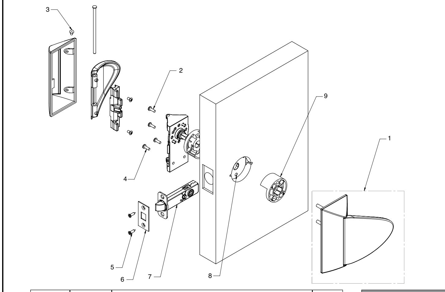
| Item No. | Part No. | Description | Req. |
|---|---|---|---|
| 1 | ––– | Inside Trim Set (ALP) | 2 |
| ––– | Outside Trim Set (ALP) | ||
| 2 | 01-1495 | # 8-32 x 5/8" Machine Screw | 2 |
| 3 | 01-9379 | # 8-32 x 5/16" Machine Screw | 4 |
| 4 | 01-1500 | # 8 x 1/2" Wood Screw | 4 |
| 01-1224 | # 8-32 x 9/16" Machine Screw | ||
| 5 | 01-5000 | Front Screw #8-32 x 3/4" Combination Screw | 2 |
| 6 | ––– | HP Outside Front Plate | 1 |
| 7 | ––– | Latch - Varies by Function | 1 |
| 8 | DL-0071 | Fire Guard Clip | 1 |
| 9 | HP-0021 | 161 Spacer | 2 |
| 10 | HP-0007 | Push Button (65 Function Only) - Not Shown | 1 |
| 11 | 81-0723 | Mounting Post - Not Shown | 1 |
| 12 | DL-0019 | Strike Box - Not Shown | 1 |
| 13 | ––– | Strike- Varies - Not Shown | 1 |
| 14 | ––– | Strike Screws- Varies - Not Shown | 2 |
| Tools Required: | ||
|---|---|---|
| Phillips screwdriver #2 | ||
| Drill | ||
| 7/46" Drill Bit (Wood Door) | ||
| #8-32 Tap (Metal Door) | ||
| 0.136" (#18) Tap Drill | ||
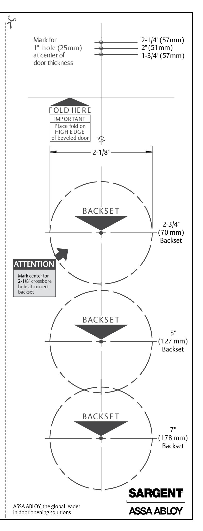
Refer to door template 4695 for required door preparation
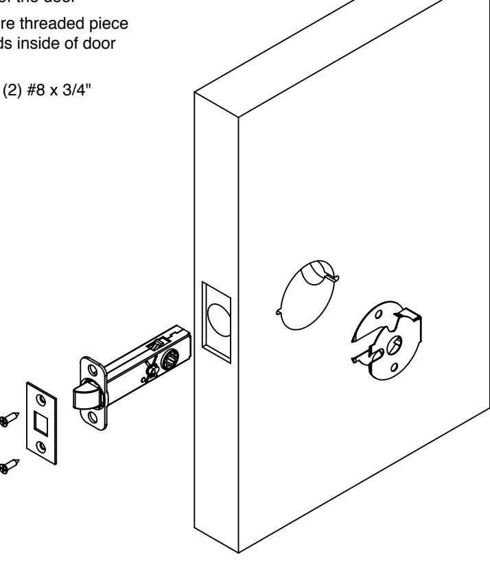
STEP 1
Install of Latch
- • Slide fire clip into door
- • Slide latch into the edge of the door
- • Position latch to make sure threaded piece on latch is pointed towards inside of door (for 65 function locks)
- • Secure latch in door with (2) #8 x 3/4" combination screws
Do not tighten fully
STEP 2
Determine Orientation of Trim
*NOTE: Chassis is packed with the cover and paddle attached. Remove prior to starting Step 3.
• The trim can be mounted vertically or horizontally
Note: Vertical mount required for 65 function (Privacy)
• Position and verify the spindle is engaged into the latch hubs
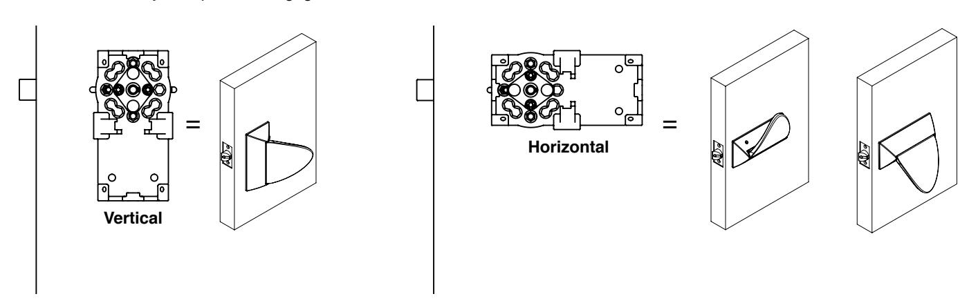
• Cams must be oriented as shown
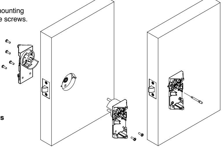
STEP 3
Installation of Chassis
- 1. Press Plastic 161 spacers onto (2) chassis [one up / one down]
- 2. Through bolt the (2) chassis to each other by inserting the (2) mounting posts from the outside and secure with (2) #8-32 x 5/8" machine screws.
Do not tighten screws fully at this point.
- 3. Level Chassis, verifying both chassis are horizontal and vertical to door edge.
- 4. Tighten through bolts.
- 5. Firmly tighten latch screws.
- 6. Install surface mounted screws.
- For wood doors: 7/64" pilot hole
- For metal doors: drill and tap for a #8-32 screw
- 7. Check operation by turning cams by hand. If binding occurs loosen mounting screws and retighten.
- 8. For 65 function (Privacy), install push button on inside of door.
IMPORTANT! Both chassis must be square to the door to ensure proper operation.
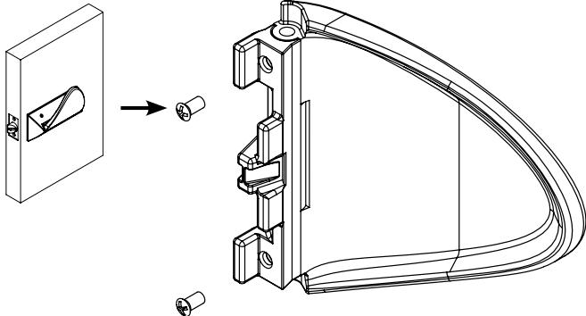
STEP 4
Determine Paddle Orientation
-
•
The paddle has three potential orientations:
- VERTICAL
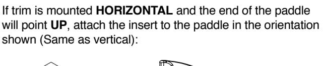
- HORIZONTAL- UP
- HORIZONTAL- DOWN
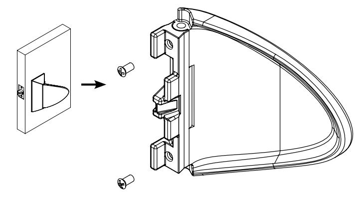
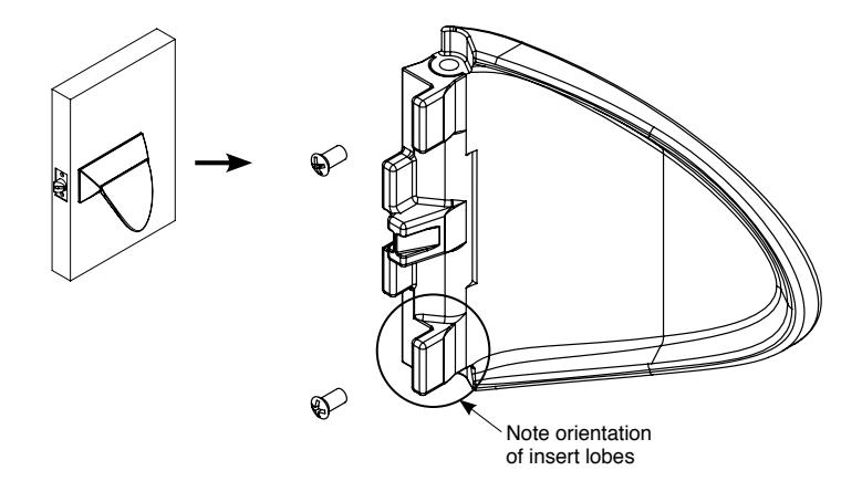
- • The insert is attached to the paddle using (2) #8-32 x 5/16" Machine Screws – VC-3 Coated
If trim is mounted VERTICAL and the end of the paddle will point towards the HINGE , attach the insert to the paddle in the orientation shown:
If trim is mounted HORIZONTAL and the end of the paddle will point DOWN , attach the insert to the paddle in the orientation shown:
Copyright © 2010, Sargent Manufacturing Company, an ASSA ABLOY Group company. of Sargent Manufacturing Company is prohibited. A8054A 10-29-10 3
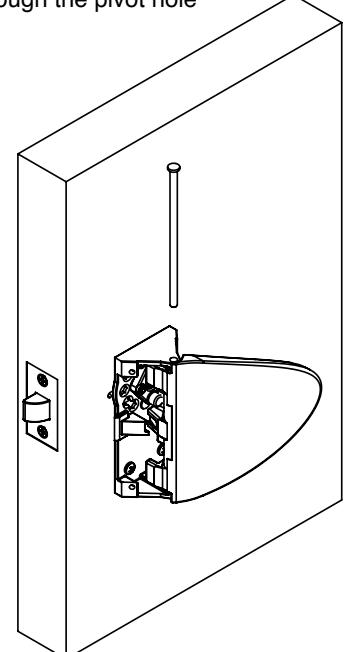
STEP 5
Installation of Paddles
• Attach paddle to the chassis in the desired orientation by inserting the axle through the pivot hole
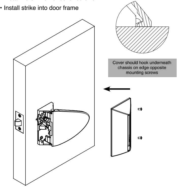
STEP 6
Installation of Covers
- • Slide cover over paddle
- • Press cover against door surface and slide back until mounting holes align with those of the chassis
- • Install #8-32 x 5/16" cover screws