HID-ProxPoint-Guide
Open the original PDF document
View PDF| REV | DESCRIPTION | DATE | APPROVED |
|---|---|---|---|
| С | REVISED PER EO# E6005-17 |
NOTE: Cover sheet is for Revision Control only, and is not to be sent with document.
| REV | ||||||||||||||||||
|---|---|---|---|---|---|---|---|---|---|---|---|---|---|---|---|---|---|---|
| SHEET | 34 | 35 | 36 | 37 | 38 | 39 | 40 | 41 | 42 | 43 | 44 | 45 | 46 | 47 | 48 | 59 | 50 | 51 |
| REV | ||||||||||||||||||
| SHEET | 16 | 17 | 18 | 19 | 20 | 21 | 22 | 23 | 24 | 25 | 26 | 27 | 28 | 29 | 30 | 31 | 32 | 33 |
| REV STATUS | С | С | С | |||||||||||||||
| OF SHEETS | 0 | 1 | 2 | 3 | 4 | 5 | 6 | 7 | 8 | 9 | 10 | 11 | 12 | 13 | 14 | 15 | ||
| TOLERANCES | APPROVALS | DA | ATE | HID CORPORATION | ||||||||||||||
| .XX = +/03" | DW | DWN ANDRESKY | 060500 | IRVINE, CALIFORNIA | ||||||||||||||
| .XXX = +/010" CHK R. OKUDA 071800 | Installation Manual, | |||||||||||||||||
| ANGLES = +/- 1° | APVD M. RIVOLI | 071800 | ProxPoint Reader | |||||||||||||||
| MATERIAL N/A | AP' | APVD B. HOLLAND | 071800 | |||||||||||||||
| FINISH N/A | THIS DOCUMENT CONTAINS PROF | P/N 6005-910 REV C | V C | |||||||||||||||
| SCALE N/A | OTHERS OR USED FOR MANUFACTURING PURPOSES WITHOUT THE PERMISSION OF HID CORPORATION | SIZE A SHEET 0 OF 2 | 2 | |||||||||||||||

Install Manual – 6005-910 Rev C ProxPointTM Installation Manual

| PARTS LIST (Included) | Quantity |
|---|---|
|
- ProxPoint™ Reader with snap-on
cover and 18" cable |
1 |
| - #4-24 x 1" self-tapping flathead screw | 2 |
| - Installation manual | 1 |
| Quantity |
|---|
| 9 |
| 1 |
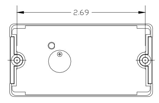
Mounting Instructions
- Determine an appropriate mounting location. The reader may be mounted to any surface, including metal.
- Drill two (2) 5/64-inch (2mm) holes approximately 1 inch deep for mounting the reader.
- Drill a 5/8-inch (16mm) hole for the cable.
- Remove the snap-on cover from the reader and secure the reader to the mounting surface.
- Route the cable from the reader and/or power supply to the host. A linear type power supply is recommended. Check all electrical codes for proper cable installation.
- Test the operation of the reader. After completion of the test, replace the snap-on cover.
- For proper regulatory compliance, the drain wire should be disconnected at the power supply end of the cable.
- Changes or modifications not expressly approved by the party responsible for compliance could void the user's authority to operate the equipment.
- The Reader is intended to be powered from a limited power source output of a previously certified power supply.
- In cold climates (-20°F), when operating the Reader from a 5V power supply, limit the cable distance to 200ft. For longer cable distances, 12V is required.
Connecting the Reader to the Host
Connect the reader to the host according to the wiring table below and the host installation guide.
| Wiegand | Clock & Data | Wire Color | |||
|---|---|---|---|---|---|
| +DC | +DC | Red | |||
| Ground | Ground | Black | |||
| Card Present | Violet | ||||
| Data0 | Data | Green | |||
| Data1 | Clock | White | |||
| Shield Ground | Shield Ground | Drain | |||
| Green LED | Green LED | Orange | |||
| Red LED | Red LED | Brown | |||
| Beeper | Beeper | Yellow | |||
| Hold | Hold | Blue | |||
Testing and Operation
- When power is applied to the reader the LED will flash green three (3) times while the beeper beeps simultaneously. The LED will then turn red. This indicates that the microcontroller is operating properly.
- Present an ID card to the reader. The LED will momentarily turn green while the beeper beeps once, indicating that the card was read successfully.
Important Product Specifications
Power requirements (linear supply)
Operating Voltage Range 5.1 – 16.0 VDC Peak Current 80 Ma Average Current 5V or 12V 20 Ma
Maximum cable distance 500 ft (153 m)
To host
Maximum cable distance 200 ft (61 m)
To host @5V
FCC Compliance Statement: This device complies with part 15 of the FCC rules. Operation is subject to the following two conditions: (1) this device may not cause harmful interference, and (2) this device must accept any interference received, including interference that may cause undesired operation.