HID-Indala-Reader-Installation-Guide
Open the original PDF document
View PDF

Indala Reader Installation Guide
FCC
This device complies with part 15 of the FCC rules. Operation is subject to the following two conditions: (1) this device may not cause harmful interference, and (2) this device must accept any interference received, including interference that may cause undesired operation.
Changes or modifications not expressly approved by the party responsible for compliance could void the user's authority to operate the equipment.
UL
This Proximity Reader is intended to be powered from a limited power source output of a previously certified power supply.
1.1 Introduction
Indala Arch, Linear, Wave, and Curve readers use a common core electronics module with different snap on bezels. The Slim (mullion) and Wallswitch module CEM (FP0500A) mounts easily to any North American standard electrical single gang box with no drilling required. The Midrange core electronics module (FP0200A) mounts easily to a North American standard electrical double gang box, also with no drilling required.
The Linear Classic readers are a direct replacement for Wiegand Swipe readers, and use the same mounting holes and hardware as the Wiegand readers being removed.
1.2 Unpacking and Identifying Supplied Parts
Unpack the contents and become familiar with the components. The following items will be included with Indala readers:
Format
- 1. Installation guide.
- 2. Indala reader module for Slim/Wallswitch, or for Midrange.
- 3. Bezels for Linear, Arch, Curve or Wave style
1.3 Identifying the Reader Format
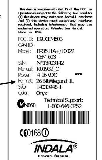
The reader and card formats must match. The Access Control System must be programmed to accept the reader format. (refer to Access Control System instructions) The reader format is printed on the ID label (see figure) attached to the reader core electronics module.
September 2010 Page 1 of 7

2.0 Installation
2.1 Mechanical Installation
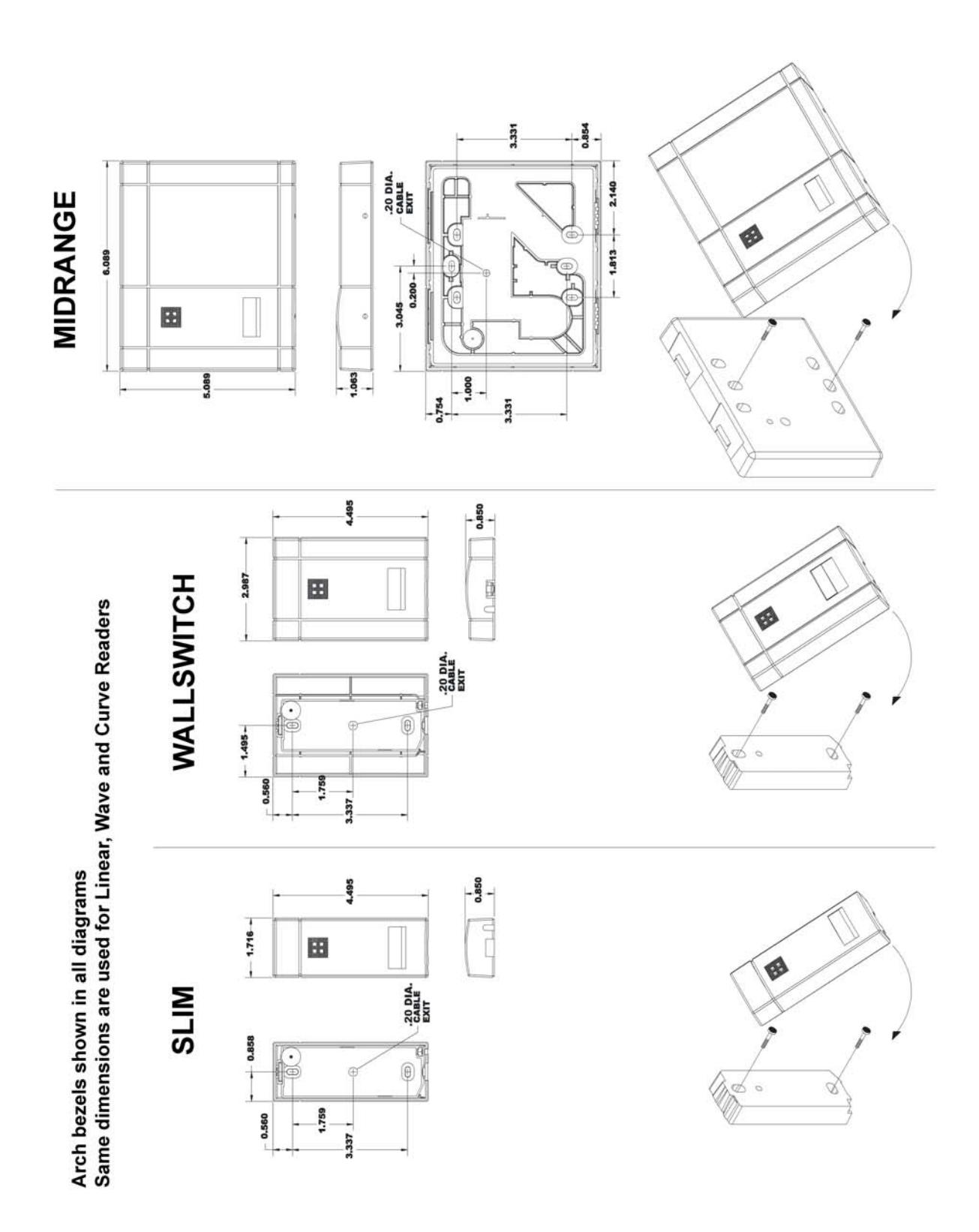
Refer to pages 5 and 6 for reader style.
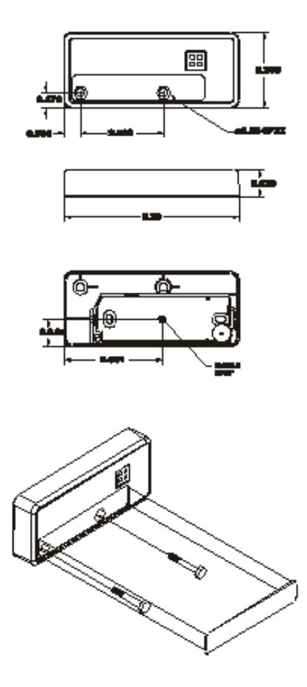
2.1.1 Mullion Mounting (Slim model only)
Mount the Core Electronics Module to a mullion by drilling two vertical pilot holes 3.3" (8.38 cm) apart for #6 or M-3 sheet metal or thread forming screws. Locate and drill a 0.375" (0.95 cm) hole for the 0.20" diameter reader cable. (See diagrams on page 5 and 6.)
Route the cable through the center hole to the controller, mount the core electronics module to the mullion, and snap on the supplied bezel.
2.1.2 Wall Mounting (Wallswitch and Midrange models)
The Wallswitch or Midrange readers can be mounted to either to a pre-installed electrical gang box, or directly to a wall. When mounting to an electrical box, make sure the gang box mounting holes fit the reader mounting holes and use two 6-32 screws to attach the reader to the gang box. Once the reader module is screwed in place, snap on the reader bezel.
If no electrical gang box is available, the core electronics module can be mounted directly to any surface by using appropriate hardware for the surface and two vertical mounting holes 3.3" (8.38 cm) apart. A 0.375" (0.95 cm) hole for the 0.20" diameter reader cable is also required. (See diagrams on page 5 and 6.) Route the cable through the center hole to the controller, mount the core electronics module to the wall, and snap on the supplied bezel.
2.1.3 Indala Linear Classic Reader
Linear Classic readers mount by first snapping the core electronics module into the bezel, and then using the same mounting holes and screws removed from a Wiegand Swipe Reader. If not replacing a Wiegand swipe reader, the same methods described in 2.1.2 can be used except the mounting holes should be horizontal versus vertical. The core electronics module then needs to be mounted horizontally with the LED on the right side.
2.2 Power Supply Cable Types and Maximum Lengths
The Indala readers require a minimum voltage of 4.0 VDC. Voltage drops, caused by the cable resistance, can be made up by increasing the power supply voltage (DO NOT SET THE POWER SUPPLY VOLTAGE TO HIGHER THAN 16 VDC) . The following are the recommended cable types and maximum cable lengths for cable connecting the power supply to the reader (DO NOT USE CABLES WITH GAUGES SMALLER THAN 24 AWG):

| Cable Type | Maximum Cable Length |
|---|---|
|
24 AWG (0.60mm), three conductors, with an
overall foil shield, 9533 or equivalent. |
200' (61 m) |
|
22 AWG (0.80mm), two conductors, with an overall
foil shield, Alpha 5192 or equivalent. |
300' (91 m) |
|
18 AWG (1.20mm), two conductors, with an overall
foil shield, 5836 or equivalent. |
500' (152 m) |

2.2.1 Reader to Host Interface Wire Types and Lengths
Refer to the table below to determine the recommended wiring type at various maximum distances. Variation in distance requires different wire gauges. Because of system data termination differences, contact your system manufacturer for its exact requirements. Installation is to be in accordance with National Electric Code ANSI/NFPA 70.

| Cable Type | Maximum Cable Length |
|---|---|
|
22 AWG (0.80mm), six or eight conductor, with an
overall foil shield, Alpha 5196, 5198 or equivalent. |
200' (61m) |
|
18 AWG (1.20mm), six or eight conductor, with an
overall foil shield, Alpha 5386, 5388 or equivalent. |
500' (152m) |
2.3 Electrical Installation
2.3.1. Grounding
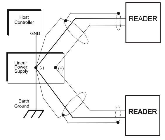
Connect the reader directly to an earth ground. An earth ground can be established by driving a copper clad ground rod into the earth. Make certain the DC resistance between your established earth ground and the system ground is 50 Ohms or less. If direct connection to a ground rod is not possible, connect the reader to an earth grounded cold water metal pipe (do not connect to copper fire sprinkler system because it may have non-conductive couplings) or steel frames (building beams) that connect to earth.
Prevent ground loops by connecting both the cable shield and the negative line of the power supply to one common earth ground point. Connecting different points to separate earth grounds may result in a ground loop. Ground loops may cause poor read range and communication line interference resulting in no code or improper code being seen by the controller.
In a multiple reader installation, connect all readers to a single earth ground reference point (common ground).

2.3.2. Reader to Host Interface Wiring
Choose the appropriate interface for your installation.
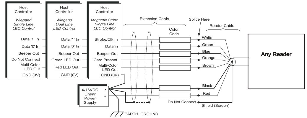
Notes:
- The system must have a single earth ground point.
- As shown above, do not connect shield (screen) wire at Flexpass reader cable splice.
- For open collector (non-terminated output), consult your system manufacturer for correct cable length and type.
2.3.3 Electrical Requirements
Slim and Wallswitch
Input voltage: 4-16 VDC
Current Draw: 100 mA MAX. 65 mA Typical @ 12 VDC
Midrange
Input voltage: 4-14 VDC
Current Draw: 140 mA MAX. 117 mA Typical @ 12 VDC

3.0 Operation
When power is first applied to the reader, it performs an internal circuit Self Test™. If it appears to be functioning properly, the reader will flash the amber LED and beep twice. After the Self Test ™ is completed, the reader is in a READY status mode and you may present the card to the reader.
3.1 Presenting the Card
To obtain maximum read range, present the card to the reader, keeping the card parallel to the reader. Move it slowly toward the face of the reader until a QuickFlash ™ (refer to section 3.3) is obtained. This is the point at which the card is read and the data is transmitted to the controller. To read the card again, remove it away from the antenna field and present it again. During normal use, the card can be presented to the antenna at any angle, although this will result in a reduced read range.
3.2 Data Output
The readers are capable of outputting in either Wiegand or magnetic stripe formatted data. For further information please call technical support at (800) 646-3252
3.3 QuickFlash ™
Unless QuickFlash™ is activated when a valid card is presented, the LED will flash and the audio tone (beeper) will be activated for 70 to 100 milliseconds. This gives the user immediate feedback that the card was read and the data was sent to the controller.


HID GLOBAL, HID, the HID logo, Indala are the trademarks or registered trademarks of HID Global Corporation, or its licensors, in the U.S. and other countries.