HID-INDALA-FlexPass®-ASR-620-Long-Range-Reader-Installation-Guide
Open the original PDF document
View PDF


ASR-620++ Long Range Reader Installation Guide
July 16, 2007 Document Number K02021-000, Rev B
© 2007 HID Global Corporation. All rights reserved.
Contents
| 1 | Over | Overview | |||
|---|---|---|---|---|---|
| 1.1 | Parts List | 3 | |||
| 1.2 | Product Specifications | 3 | |||
| 1.3 | Features | 4 | |||
| 1.4 | Reader Format | 4 | |||
| 2 | Insta | allation | 5 | ||
| 2.1 | Mechanical | 5 | |||
| 2.2 | Dimension Drawing | 6 | |||
| 2.3 | Cabling | 7 | |||
| 2.4 | Electrical | 8 | |||
| 2.5 | Reader to Host Interface Wiring | 9 | |||
| 2.6 | Reader Tuning | 10 | |||
| 3 | Ope | ration | 10 | ||
| 3.1 | Presenting the Card | 10 | |||
| 3.2 | QuickFlash | 11 | |||
| 3.3 | Data Output | 11 | |||
| 3.4 | Verifying Data at Host | 11 | |||
| 3.5 | Controls and Indications | 11 | |||
| Reg | ulatory | 12 | |||
| Con | tacts | 13 | |||
| . : | |||||
|
gures
ader Label |
4 | ||||
| _ | all Mounting | ||||
| - | nensions | ||||
| Figure 5 Grounding the Reader | |||||
| ader to Host Wiring | |||||
| Figure 7 Internal Circuit Configurations | |||||
| Figu | re 8 Pre | esenting the Card | 10 | ||
| Lict | of Ta | phles | |||
| ver Supply Cables | 7 | ||||
| st Interface Cables | |||||
| · uvi | 1 IUS | « III.O. 1000 Oublou | |||
1 Overview
The Indala® FlexPass® ASR-620++ Long Range Reader is a rugged radio frequency reader designed for applications such as identification systems, security systems, and data collection. The reader mounts on most flat surfaces with the electronics enclosed in a gasket sealed cover to provide weather resistance. The ASR-620++ outputs data in Wiegand or ABA Track II (MagStripe) formats. Sold separately is an optional RS-232 interface that requires the use of a BIL-422/232 signal-conditioning module.
1.1 Parts List
Unpack the equipment and become familiar with the components.
| Description | Quantity |
|---|---|
| ASR-620++ reader electronics module | 1 |
| ASR-620++ cover | 1 |
| Tuning tool | 1 |
| O rings | 7 |
1.2 Product Specifications
| Description | Specification | |
|---|---|---|
| Input voltage | 12.0 VDC to 24 VDC | |
| Input current/power | ||
| - Typical, quiescent off metal |
Vin = 12.0 VDC
1.0 A 12 W Vin = 24.0 VDC 750 mA 18.0 W |
|
| - Maximum, quiescent off metal |
Vin = 12.0 VDC
1.2 A 14.4 W Vin = 24.0 VDC 920 mA 22.1 W |
|
| - Maximum power |
12 VDC ≤ Vin ≤ 24 VDC
22.1 W |
|
| Recommended power supply |
Regulated linear power supply
12 VDC at 1.5 A (per reader) 24 VDC at 1.0 A (per reader) |
|
|
Read range with the HID Global
FlexCard® |
Up to 26.0 in (66.0 cm) | |
| Operating temperature range | -35°C to +65° C (-31°F to +149°F) (See Notes) | |
| Material |
UV resistant, ABS /polycarbonate (UL94V0)
plastic |
|
| Dimensions | 11.2" H x 11.2" W x 1.8 "T (28.4 x 28.4 x 4.6 cm) | |
| Weight | 3.2 lbs (1.45 kg) | |
| Output formats |
Wiegand, ABA track2 Magnetic Stripe
(Contact HID Technical support for other formats) |
|
Notes:
Read range is applicable in an undisturbed electrical environment. Install the reader in accordance with HID Global instructions, and present the card parallel to the reader. The power supply, reader, and controller must be on the same ground, connected to the earth.
The beeper may not be audible at temperatures below -20ºC, except at short distances.
ASR620++ reader tuning supports mounting the on non-ferrous surfaces. If mounting the ASR620++ on or near a ferrous surface, use a minimum 3 in (7.6cm) non-ferrous spacer.
Earlier versions of the ASR-620 reader required the use of a CT-620 power conditioner to meet European emissions standards; this is not applicable with the ASR 620++ model.
Power the ASR-620++ from a limited power source which is certified. Use with UL 294 listed control equipment.
1.3 Features
- QuickFlash™ for immediate user feedback
- SelfTest™ for installer assistance during installation
- WatchDog™ for increased supervisory control
- Independently controlled audio-tone and tri-color status LEDs
- Field programmability via ProxSmith™ software (available separately) and option cards
- Mounting on most flat surfaces
- Indoor/outdoor operation
- Attractive, contemporary styling
1.4 Reader Format
The reader format is printed on the ID label (See Figure 1 Reader Label) located on the rear of the base assembly, and under the cover on one of the two metal shields.
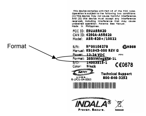
Figure 1 Reader Label
2 Installation
2.1 Mechanical
Proper operation of the reader requires mounting it to a vertical surface with the LEDs located in the top left corner.
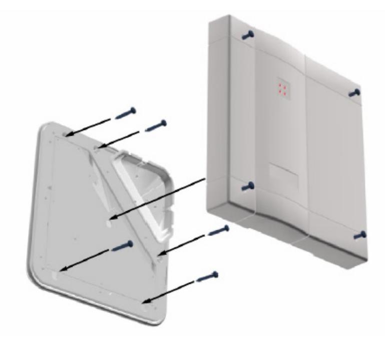
Figure 2 Wall Mounting
- 1. Drill the mounting holes to a #8 clearance and drill the cable hole to at least 13/16" (0.813") diameter.
- 2. Remove the cover from the base and feed the cable through the cable clearance hole.
- 3. Attach the reader to the wall using #8 screws.
- 4. Ensure the O-rings are installed between the mounting screw heads and the base housing (do not over-tighten the screws).
- 5. Route the reader cable to the controller. (For dimensions, cable and hole locations see Figure 3 Dimensions)
Note: The ASR0-620++ reader is tuned for mounting on non-ferrous surfaces. If the reader must be mounted on, or near, a ferrous surface, use a minimum 3 inch (7.6cm) non-ferrous spacer.
2.2 Dimension Drawing
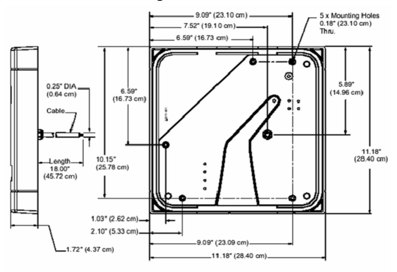
Figure 3 Dimensions
2.3 Cabling
2.3.1 Power Supply
The ASR-620++ reader requires a minimum voltage of 12.0 VDC at the reader. Overcome voltage drops, caused by the cable resistance, by increasing the power supply voltage. Do not set the power supply voltage to higher than 28 VDC. In noisy environments, use shorter cable runs. (See Table 1 Power Supply Cables for the recommended cable types and cable lengths). Do not use cables with gauges smaller than 22 AWG for cables connecting the power supply to the reader.
Table 1 Power Supply Cables
| Cable Type | 12V Cable Length | 24V Cable Length | |||
|---|---|---|---|---|---|
|
22 AWG (0.80 mm), two
conductors, with an overall foil shield, Alpha 5192 or equivalent. |
30 ft (9.1 m) | 44 ft (13.7 m) | |||
|
18 AWG (1.20 mm), two
conductors, with an overall foil shield, Alpha 5386 or equivalent. |
80 ft (24.4 m) | 120 ft (36.6 m) | |||
2.3.2 Host Interface
Refer to Table 2 Host Interface Cables to determine the recommended wiring type at various maximum readers to host distances. Due to system termination differences, and the variation in distance requires different wire gauges, contact your system manufacturer for exact requirements. Installation should be in accordance with national electric code ANSI/NFPA 70 (or the applicable regulatory standards in countries outside the USA).
Table 2 Host Interface Cables
| Cable Type | Maximum Cable Length |
|---|---|
|
22 AWG (0.80mm), six or eight conductor, with an
overall foil shield, Alpha 5196, 5198 or equivalent. |
500'(152 m) |
Note: Ensure an active low-level voltage of less than 0.6 V, and the total ground resistance from the reader to the controller is less than 0.5 ohms. Use larger gauge wire if necessary.
2.4 Electrical
2.4.1 Grounding
Connect the reader directly to an earth ground as shown in Figure 4 Grounding the Reader. Establish an earth ground by driving a copper clad ground rod into the earth. Confirm the DC resistance between your established earth ground and the system ground is very low. If direct connection to a ground rod is not possible, connect the reader to an earth-ground. Do not connect to a fire sprinkler system, or to steel frames (building beams) that connect to the earth.
Prevent ground loops by connecting the controller ground and the negative line of the power supply to one common earth ground point. Connecting different points to separate earth grounds may result in a ground loop. Ground loops may cause poor read range and communication line interference resulting in no code or improper data transmission to the controller. In a multiple reader installation, connect all readers to a single earth ground reference point (common ground).
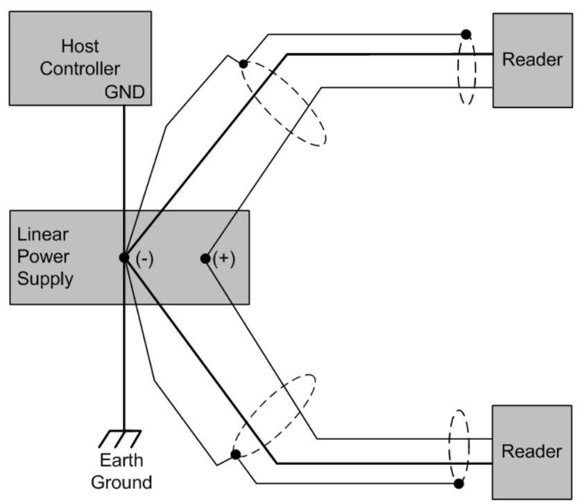
Figure 4 Grounding the Reader
Note: A multiple reader installation requires a higher maximum current rated power supply. See section 1.2 Product Specifications, page 3.
2.5 Reader to Host Interface Wiring
Figure 5 Reader to Host Wiring shows interfaces for Magstripe and Wiegand host controllers. Choose the appropriate interface for your installation.
Note : RS-232 configuration requires a BIL-422/232 signal-conditioning module (purchase a separate).
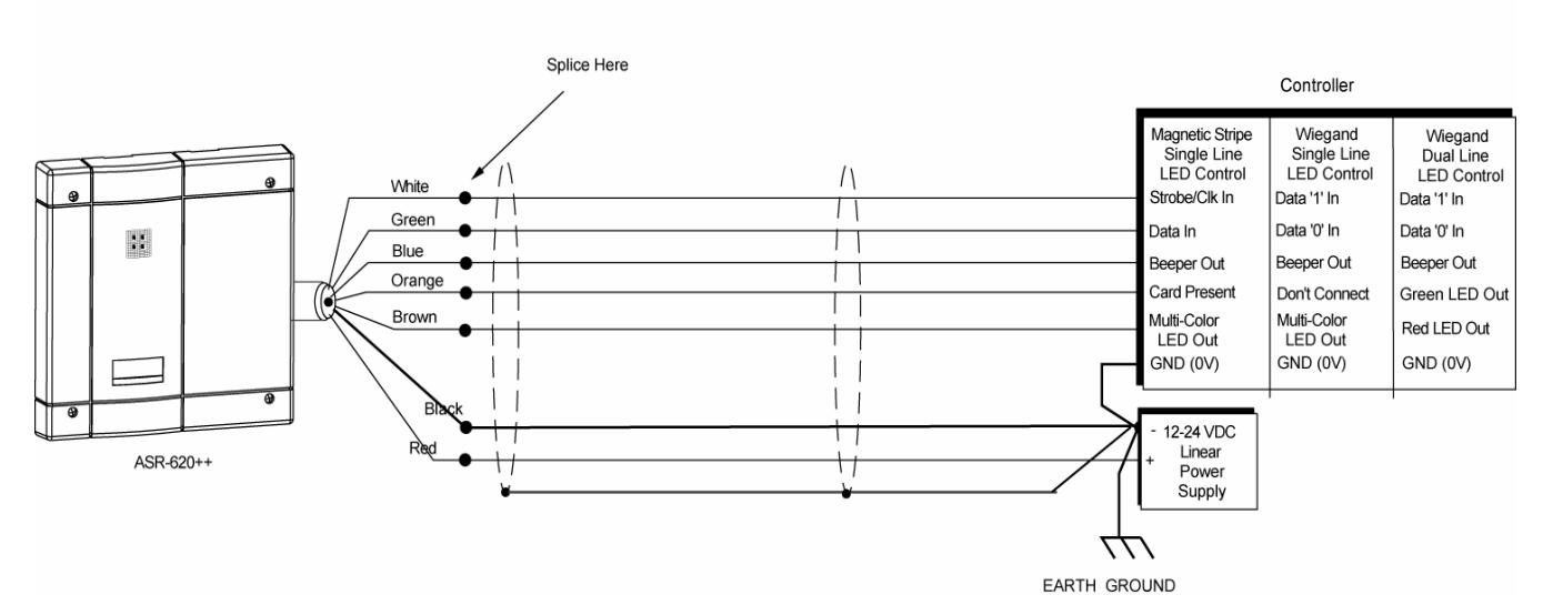
Figure 5 Reader to Host Wiring
Notes:
The system must have a single earth ground point.
For regulatory compliance, connect the drain wire at the power supply end of the I/O cable.
For open collector (non-terminated output), consult your system manufacturer for correct cable length and type. The internal circuit configurations for the reader inputs and outputs are as shown in Figure 6 Internal Circuit Configurations.
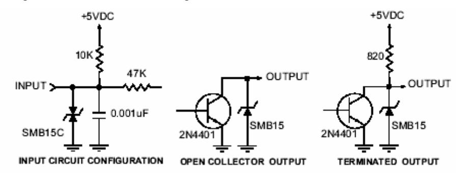
Figure 6 Internal Circuit Configurations
2.6 Reader Tuning
Tuning the reader is not necessary in most installations. The reader should be mounted and tested for read range and host output function prior to attempting an adjustment of the reader. For guidance in re-tuning this reader, call HID technical support (see Contacts). The installer should be familiar with the adjustment procedure and complete the adjustment in a controlled environment prior to attempting to make adjustments at the installation location.
Note: Do not attempt to tune the reader without the required tools and equipment. Improper tuning of the reader can significantly degrade reader performance and may invalidate the warranty.
3 Operation
When power is first applied, the reader performs internal diagnostics to ensure reader operation and test the integrity of the data lines. If the reader is functioning properly, the reader will flash the LED and beep twice. After the diagnostics are completed, the reader is ready and you may present a standard or option card to the reader. If the reader start-up routine determines that one of the critical memory devices inside the reader has failed, the reader will flash the LED red and green.
3.1 Presenting the Card
To obtain maximum read range, present the card to the reader, as shown in Figure 7 Presenting the Card. Keep the card parallel to the reader and move it slowly toward the face until observing a QuickFlash. The card is read and the data is transmitted to the controller at this is the point.
To read the card again, remove it from the reader field and represent it as above. During normal use, present the card to the reader at any angle, although this may result in a reduced read range.
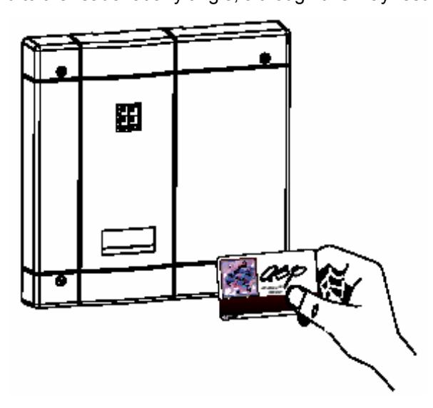
Figure 7 Presenting the Card
3.2 QuickFlash
When presenting a valid card, the LED will flash and activate an audio tone (beeper) for 70 to 100 milliseconds regardless of the access status of the card. Immediate feedback that the card was read and that data was sent to the controller is provided to the user. After the QuickFlash period, the controller takes over the LED and beeper.
3.3 Data Output
The ASR-620++ reader is capable of Wiegand, Magstripe, or RS-232 output (RS-232 requires additional hardware). For further information please contact HID technical support (see Contacts).
3.4 Verifying Data at Host
Verify that the data lines are good by putting the reader into line test mode; do so by holding a SelfTest card in front of the reader. The reader will respond with an alternately flashing LED in all three colors and an audio signal. Until removing/reapplying power, the reader will remain in the line test mode. Presenting the SelfTest or other option card also removes the reader from the line test mode.
While in the line test mode, the reader sends output pulses at a 1 Hz rate. Measure these pulses at the controller with a voltmeter. If the pulses are not present, then there is probably a break or short in the line. If the pulses are present and the system is still not working, confirm correct connection of the reader to the host controller. It may also be possible that the host controller is incorrectly programmed or otherwise non-functional.
3.5 Controls and Indications
3.5.1 Single-Line Control LED Host to Reader Wiring
There is no LED off state in this configuration. The LED is red when the brown wire is high above 2.2 VDC or not connected.
- Pull the brown wire low to change the LED color to green.
- Toggle the brown line high then low at a rate of 100 Hz to 1 kHz to produce the amber LED.
- Pull the blue beeper wire low to activate the audio beep tone.
3.5.2 Dual-Line Control LED Host to Reader Wiring
The LED is off when both the brown and orange wires are high above 2.2 VDC or not connected.
- Pull the brown wire low to activate red LED.
- Pull the orange wire low to activate green LED.
- Pull the orange and brown wires low simultaneously to activate the amber LED.
- Pull the blue wire low to activate the audio beep tone.
3.5.3 Option Cards
3.5.3.1 Single-Line and Dual-Line LED Control
This option card toggles the state of the LED control lines. If one beep is heard when the card is presented, the reader is set to a single-line LED control. The reader is in dual-line LED control if two beeps are heard.
3.5.3.2 QuickFlash Beep
This option card toggles the state of the QuickFlash beep option. If one beep is heard when the card is presented to the reader, the automatic beep is enabled. The automatic QuickFlash beep is disabled if two beeps are heard.
3.5.3.3 QuickFlash LED
This option card toggles the state of the QuickFlash LED option. If one beep is heard when the card is presented to the reader, the automatic QuickFlash is enabled. If two beeps are heard, the automatic QuickFlash LED is disabled.
3.5.3.4 SelfTest
This option card enables or disables the line test mode upon presentation. Present the card once to put the reader into the line test mode. Present a second time to revert to normal operation.
3.5.3.5 WatchDog
This option card toggles the state of the automatic WatchDog option. If one beep is heard when the card is presented to the reader, the WatchDog output is enabled. If two beeps are heard, the WatchDog output is disabled. The WatchDog will output an 8-bit '10101010'pattern (hexadecimal 'AA') approximately once every minute over the data lines.
Regulatory
FCC
This device complies with part 15 of the FCC rules. Operation is subject to the following two conditions: (1) this device may not cause harmful interference, and (2) this device must accept any interference received, including interference that may cause undesired operation.
Changes or modifications not expressly approved by the party responsible for compliance could void the user's authority to operate the equipment.
UL
This proximity reader is intended to be powered from a limited power source output of a previously certified power supply. This reader is intended to be use with UL 294 listed control equipment.
The ABA Track II (Mag Stripe) format and RS-232 interface have not been evaluated by UL.
CE Marking
HID Global hereby declares that this proximity reader is in compliance with the essential requirements and other relevant provisions of directive 1999/5/EC.
Contacts
Americas
HID Global Corporation (California, USA)
Email: tech@hidcorp.com Main: (949) 598-1600 Support: 1-800-237-7769 Fax: (949) 598-1690
Europe, Middle East and Africa
HID Global Corporation, Ltd. (Haverhill, UK)
Email: eusupport@hidcorp.com Main: +44 (0) 1440 714 850 Support: +44 (0) 1440 711 822 Fax: +44 (0) 1440 714 840
Asia-Pacific
HID Global Corporation Asia Pacific Ltd. (Hong Kong)
Email: asiasupport@hidcorp.com
Main: (852) 3160 9800 Support: (852) 3160 9802 Fax: (852) 3160 4809