HID FARGO DTCii Plus User Guide
Open the original PDF document
View PDFHID® FARGO® DTCii Plus User Guide
PLT-05151, A.2 August 2022


Copyright
© 2020 - 2022 HID Global Corporation/ASSA ABLOY AB. All rights reserved.
This document may not be reproduced, disseminated or republished in any form without the prior written permission of HID Global Corporation.
Trademarks
HID GLOBAL, HID, the HID Brick logo, DTC, FARGO, UltraCard, and iCLASS are trademarks or registered trademarks of HID Global, ASSA ABLOY AB, or its affiliate(s) in the US and other countries and may not be used without permission. All other trademarks, service marks, and product or service names are trademarks or registered trademarks of their respective owners.
MIFARE is a registered trademarks of NXP B.V. and are used under license.
Contacts
For technical support, please visit: https://support.hidglobal.com .
What's new
| Date | Description | |
|---|---|---|
| August 2022 | Adds cleaning and maintenance instructions. Updates compliance information. | A.2 |
A complete list of revisions is available in Revision history .

| Specifications | 4 |
|---|---|
| 1.1 Regulatory compliance | 5 |
| 1.1.1 Agency listings | 5 |
| 1.1.2 United States | 5 |
| 1.1.3 Canada | 5 |
| 1.2 Safety messages - United States | 6 |
| 1.3 Safety messages - French | 7 |
| 1.4 Technical specifications | 8 |
| 1.5 Functional specifications | 9 |
| 1.6 Printer components: print ribbons | 10 |
| 1.6.1 Ribbon types and print counts | 10 |
| 1.7 Printer components: blank cards | 11 |
|
Setup
and installation procedures |
12 |
| 2.1 Choosing a good location | 13 |
| 2.1.1 About moisture condensation | 13 |
| 2.2 Unpacking and inspection | 13 |
| 2.3 Installing the print ribbon cartridge | 14 |
| 2.3.1 Installing the ribbon | 14 |
| 2.4 Installing blank cards into the input card hopper | 16 |
| 2.5 Installing the output hopper | 18 |
| 2.6 Connecting the printer power | 19 |
| 2.7 Locking system | 20 |
| 2.8 Accessory procedures: using the security lock slot | 20 |
|
Cleaning
and maintenance procedures |
21 |
| 3.1 Cleaning and maintenance procedures | 22 |
|
System
overview - troubleshooting |
24 |
| 4.1 Sequence of operations | 25 |
| 4.2 Troubleshooting | 26 |
| 4.2.1 Printer error buttons | 26 |
| 4.2.2 Error messages | 26 |
| 4.2.3 Troubleshooting with the error message table | 27 |
| 4.2.4 Printer-specific tools | 30 |
|
HID
Global Technical Support |
31 |
| 5.1 Before contacting HID Global Technical Support | 32 |
| 5.2 Reading the serial numbers on a FARGO printer | 32 |
Section 01 Specifications


1.1 Regulatory compliance
| UL |
The card printer is listed under UL 62368-1 (2nd edition) Information Technology Equipment
File Number: E145118 This product is intended to be supplied by a Listed Power Unit marked Class 2 and rated for 24Vdc, 3.3A minimum. |
|---|---|
| CSA |
The card printer manufacturer has been authorized by UL to represent the card printer as CSA Certified under
CSA Standard C22.2 No. 62368-1-14 2nd edition File Number: E145118 |
1.1.1 Agency listings
| Emissions and Immunity Standards | FCC Part 15 Class A, RSS-GEN, RSS 210 |
|---|---|
| Safety Standards | UL IEC 62368-1 (2nd edition), CSA C22.2 No. 62368-1-14 (2nd edition) |
1.1.2 United States
This device complies with Part 15 of the FCC rules. Operation is subject to the following two conditions:
- 1. This device may not cause harmful interference.
- 2. This device must accept any interference received, including interference that may cause undesired operation.
This equipment has been tested and found to comply with the limits for a Class A digital device, pursuant to part 15 of the FCC Rules. These limits are designed to provide reasonable protection against harmful interference when the equipment is operated in a commercial environment. This equipment generates, uses, and can radiate radio frequency energy and, if not installed and used in accordance with the instruction manual, may cause harmful interference to radio communications. Operation of this equipment in a residential area is likely to cause harmful interference; in which case, you are required to correct the interference at your expense.
Important: Changes or modifications to an intentional or unintentional radiator not expressly approved by the party responsible for compliance could void the user's authority to operate the equipment.
WARNING: THIS PRODUCT CAN EXPOSE YOU TO CHEMICALS INCLUDING DIISONONYL PHTHALATE (DINP), WHICH IS A KNOWN TO THE STATE OF CALIFORNIA TO CAUSE CANCER. FOR MORE INFORMATION GO TO WWW.P65WARNINGS.CA.GOV.
1.1.3 Canada
This device complies with Industry Canada license-exempt RSS standard(s). Operation is subject to the following two conditions: (1) this device may not cause interference, and (2) this device must accept any interference, including interference that may cause undesired operation of the device.
Le présent appareil est conforme aux CNR d'Industrie Canada applicables aux appareils radio exempts de licence. L'exploitation est autorisée aux deux conditions suivantes: (1) l'appareil ne doit pas produire de brouillage, et (2) l'utilisateur de l'appareil doit accepter tout brouillage radioélectrique subi, même si le brouillage est susceptible d'en compromettre le fonctionnement.

1.2 Safety messages - United States
| Symbol | Critical instructions for safety purposes |
|---|---|
| Danger: |
Failure to follow these guidelines results in personal injury or death.
To prevent personal injury or death: Reference the following safety messages before performing an operation. l Always remove the power cord prior to performing repair procedures, unless otherwise specified. l Ensure only qualified personnel perform these procedures. l |
| ESD: |
This device is electrostatically sensitive. You may damage the device if exposing it to static electricity discharges.
To prevent damage: Reference the following safety messages before performing an operation. l Observe all established Electrostatic Discharge (ESD) procedures while handling cables in or near the circuit board and l print head assemblies. Always wear an appropriate personal grounding device. l Always remove the ribbon and cards from the printer before making any repairs, unless otherwise specified. l Remove jewelry and thoroughly clean hands before working on the printer. l |
| Caution: | This symbol warns of an electrical hazard that could result in personal injury or death. |
| Caution: | For safety purposes, do not use Ethernet for a direct connection outside of the building. |

1.3 Safety messages - French
| Symbole | Instructions critiques visant la Sécurité |
|---|---|
| Danger: |
Si ces directives ne sont pas suivies les résultats peuvent être des lésions corporelles ou la mort.
Pour éviter des lésions corporelles ou la mort: Rapportez-vous aux avis suivants de sécurité avant de procéder à une opération. l Retirez toujours le câble d'alimentation avant d'effectuer des procédures de réparation, sauf spécification contraire. l Assurez-vous qu'uniquement des personnes qualifiées réalisent des procédures. l |
| ESD: |
Ce dispositif est sensible à l'électricité statique. Il peut souffrir des dommages s'il est exposé à des décharges
électrostatiques. Pour éviter des dommages: Rapportez-vous aux messages suivants avant de procéder à une opération. l Suivez toutes les procédures de Décharges Electrostatiques (ESD) en vigueur durant le maniement des câbles dans ou à l proximité des Ensembles de Cartes de Circuit Imprimé et Tête d'Impression. Portez toujours un dispositif de mise à la terre personnelle appropriée. l Retirez toujours le ruban et les Cartes de l'Imprimante avant d'effectuer toute réparation, sauf spécification contraire. l Retirez tous bijoux et lavez soigneusement vos mains avant de travailler à l'Imprimante. l |
| Attention: | Ce symbole est un avis de péril électrique passible de résulter en lésion corporelle ou mort. |
| Attention: | Pour des motifs de sécurité, n'utilisez pas Ethernet pour une connexion directe hors du bâtiment. |

1.4 Technical specifications
| Term | Function | ||
|---|---|---|---|
| Print Method | Dye Sublimation / Resin Thermal Transfer | ||
| Print resolution | 300 dpi (11.8 dots/mm); continuous tone | ||
| Colors | Up to 16.7 million colors / 256 shades per pixel | ||
| Print Ribbon Options | Full color with two resin black panels and overlay panel - YMCKOK* (200 prints) | ||
| Silver metallic resin with overlay panel and resin black panel - SOK* (350 prints) | |||
| Resin black and overlay panel, KO* (1250 prints) | |||
|
* Indicates the ribbon type and the number of ribbon panels printed where Y=Yellow, M=Magenta,
C=Cyan, K=Resin Black, O=Overlay, F=Fluorescing Resin |
|||
| Print Speed | 12 seconds per card (KO*) | ||
| 24 seconds per card (YMCKOK*) | |||
|
Print speed indicates an approximate batch print speed and is measured from the time a card feeds
into the printer to the time it ejects from the printer. |
|||
| Print speeds do not include encoding time or the time needed for the PC to process the image. | |||
|
Process time is dependent on the size of the file, the CPU, amount of RAM and the amount of available
resources at the time of the print. |
|||
|
* Indicates the ribbon type and the number of ribbon panels printed where Y=Yellow, M=Magenta,
C=Cyan, K=Resin Black, O=Overlay, F=Fluorescing Resin |
|||
| Card Size and Types Supported | CR-80 (3.375" L x 2.125" W / 85.6mm L x 54mm W) | ||
| Accepted Standard Card Sizes | CR-80 edge-to-edge (3.36" L x 2.11" W / 85.3mm L x 53.7mm W) | ||
| Accepted Card Thickness | .009"040" / 9 mil – 40 mil/.229mm – 1.016mm | ||
| Accepted Card Types |
Press polished PVC
l |
||
|
Laminated PVC (credit card construction)
l |
|||
|
Blank white chip/mag
l |
|||
|
Dual interface MC and/or Visa
l |
|||
| Input Hopper Card Capacity | 200 cards (.030"/.762 mm) | ||
| Output Hopper Card Capacity | 100 cards (.030"/.762.mm) | ||
| Reject Hopper Card Capacity | 100 cards (.030"/.762.mm) | ||
| Card Cleaning | Card cleaning roller integrated into the ribbon cartridge. | ||
| A new cleaning roller is included with each ribbon cartridge. | |||
| Printer Memory | 32MB RAM | ||
| Operating Systems | Windows Server 2003 | ||
| Windows Server 2008 | |||
| Windows Server 2016 | |||
| Windows Server 2019 | |||
| Windows 7 (32- and 64 bit) | |||
| Windows 10 (32- and 64-bit) | |||
| Interface | Ethernet with internal print server | ||

| Term | Function |
|---|---|
| Operating Temperature | 65° F to 90° F / 18° C to 32°C |
| Humidity | 20-80% non-condensing |
| Dimensions (with output bin) | 9.8"H x 22.9"W x 9.2"D/249mm H x 583mm W x 234mm D |
| Weight | 13 lbs / 6 Kg |
| Supply Voltage | 100-240 VAC, 1.6 A |
| Supply Frequency | 50 Hz / 60 Hz |
| Warranty | Printer – Three years; Printhead – Three years, unlimited pass with UltraCard® |
| Encoding Options Supported | 125 kHz (HID Prox) reader |
| 13.56 MHz (iCLASS®, MIFARE, ISO 14443 A/B, ISO 15693) read/write encoder | |
|
Contact Smart Card Encoder reads from and writes to all ISO7816 1/2/3/4 memory and
microprocessor smart cards (T=0, T=1) as well as synchronous cards |
|
| ISO Magnetic Stripe Encoding, dual high- and low-coercivity, Tracks 1, 2 and 3 | |
| Display | Graphical Display |
1.5 Functional specifications
This card printer utilizes two different, yet closely related printing technologies to achieve its remarkable card print quality for dye-sublimation and resin thermal transfer.

1.6 Printer components: print ribbons
The card printer utilizes both dye-sublimation and/or resin thermal transfer methods to print images directly onto blank cards. Since the dye-sublimation and the resin thermal transfer print methods each provide their own unique benefits, print ribbons are available in resin-only, dye-sublimation-only and combination dye-sublimation/resin versions.
To make it easier to identify the print ribbons, a letter code has been developed to indicate the type of ribbon panels found on each ribbon:
| Dye -Sublimation Yellow Panel | ||
|---|---|---|
| Dye-Sublimation Magenta Panel | ||
| Dye-Sublimation Cyan Panel | ||
| Resin Black Panel (Premium unless otherwise stated) | ||
| Clear Protective Overlay Panel | ||
| Fluorescing Panel | ||
1.6.1 Ribbon types and print counts
| Ribbon | Print count |
|---|---|
| YMCKOK - Full Color / 2 Resin Black / Overlay | 200 |
| KO - Premium Black Resin / Overlay | 500 |
| SOK - Silver Metallic Resin / Overlay / Resin Black | 350 |

1.7 Printer components: blank cards
| Type | Description | |
|---|---|---|
| Card Size | The card printer accepts standard CR-80 sized cards. | |
| Card Surface |
Suitable cards must have a polished PVC surface free of fingerprints, dust or any other types of
embedded contaminants. In addition, cards must have a completely smooth, level surface in order for the printer to achieve consistent color coverage. Certain types of Proximity cards have an uneven surface that inhibit consistent color transfer. |
|
|
Certain types of smart card chips are raised slightly above the cards surface which results in
poor color transfer. |
||
| UltraCard Brand Cards |
The UltraCard® product line, available exclusively as part of HID Global FARGO brand secure
card issuance solutions, has a long standing reputation among dealers and end-Users for consistent quality in construction. |
|
|
In addition to blank stock, the UltraCard line is available in a variety of configurations for
magnetic stripe, custom holograms, and other additional anti-counterfeiting features. UltraCard Premium is the preferred card for Direct-to-Card (DTC) applications that require a l higher quality card. The composite material construction provides for maximum durability, flexibility and card life, with optimal resolution print quality for lamination and fluorescent panel ribbon printing applications. UltraCard PVC cards are medium-durability cards for a glossy, photo quality finish. These l cards are manufactured to ensure clean, scratch-free cards for high-quality prints and extended printhead life. |
||
Section 02 Setup and installation procedures


2.1 Choosing a good location
The following guidelines help to ensure optimal printing performance:
- l Place the unit in a location with adequate air circulation to prevent internal heat buildup.
- l Use the printer's dimensions as a guideline for the minimum clearances to the unit.
Note: Allow for adequate clearance in front of the unit to accommodate the unit with its covers open.
l Do not install unit near heat sources such as radiators or air ducts or in a place subject to direct sunlight, excessive dust, mechanical vibration or shock.
2.1.1 About moisture condensation
If the unit is brought directly from a cold to a warm location or is placed in a very damp room, moisture may condense inside the unit. Should this occur, print quality may not be optimal.
Leave the unit unplugged in a warm, dry room for several hours before using to evaporate any moisture.

Caution : For safety purposes, Ethernet is not intended for a direct connection outside of the building. Attention : Pour des raisons de sécurité, Ethernet n'est pas conçu pour une connexion directe à l'extérieur du bâtiment.
2.2 Unpacking and inspection
While unpacking your printer, inspect the carton to ensure that no damage has occurred during shipping. Make sure that all supplied accessories are included with your unit.
Check that the following items are included:
- l Power supply
- l US power cord
- l Installation Guide
- l Warranty Statement, Compliance Document

2.3 Installing the print ribbon cartridge
FARGO® Direct-to-Card Printers require highly specialized supplies to function properly.
The FARGO DTCii Plus uses a one piece, disposable ribbon cartridge system.
To maximize printer durability, reliability and printed card quality, only FARGO-certified supplies must be used. For this reason, your FARGO warranty is void, where not prohibited by law, if you use non-FARGO-certified supplies.
Printer cleaning is recommended with each ribbon change to ensure quality printed cards.
Resin-only print ribbons consist of a continuous roll of a single resin color. No protective overlay panel (O) is provided because resin images do not require the protection of an overlay.
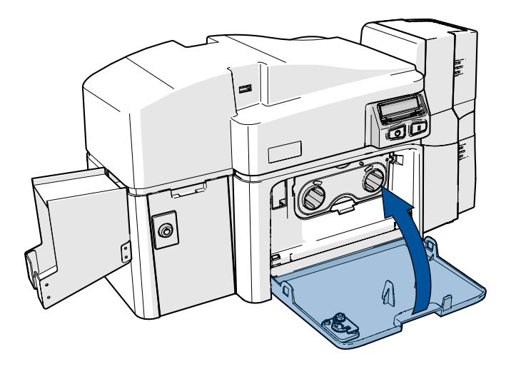
2.3.1 Installing the ribbon
1. Pull open front cover.
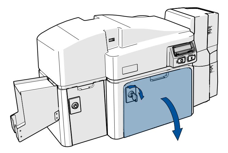
2. Insert the print ribbon cartridge into the printer.
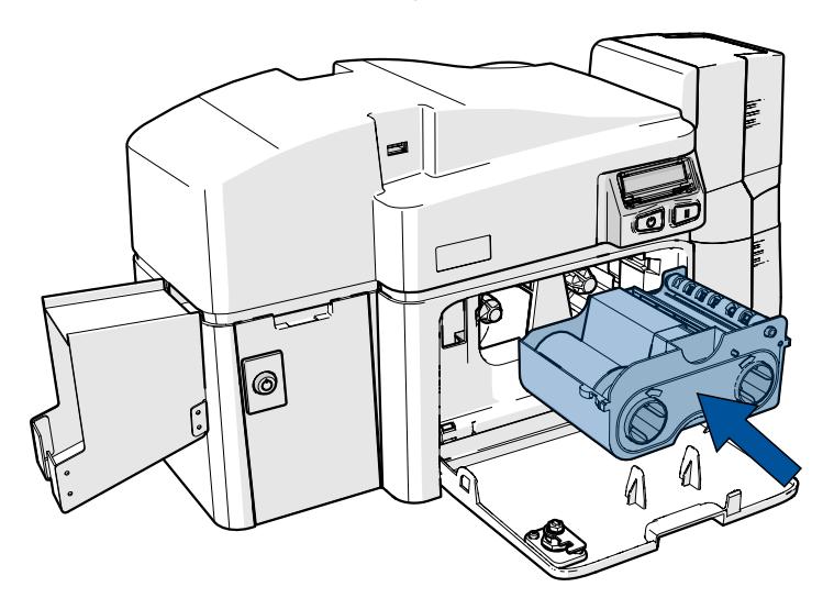

3. Close the front cover.

2.4 Installing blank cards into the input card hopper
The FARGO DTCii Plus card printer with dual input card hoppers is capable of printing different types of cards located in the upper or lower tray of the dual input hopper, for a total of 200 cards.
1. Slide up and open the dual input hopper upper door (Hopper 1).
- 2. Load up to 100 cards into the upper hopper with the print side down. If using cards with a magnetic stripe, the magnetic stripe should be loaded with the stripe up and to the front of the printer.
- 3. Close the dual input card hopper upper door to release the weight load onto the upper hopper cards.

4. Open the input hopper lower door (Hopper 2).
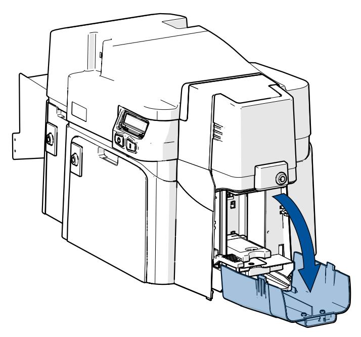
5. Press the card hopper load lever down until the card tray locks into place.
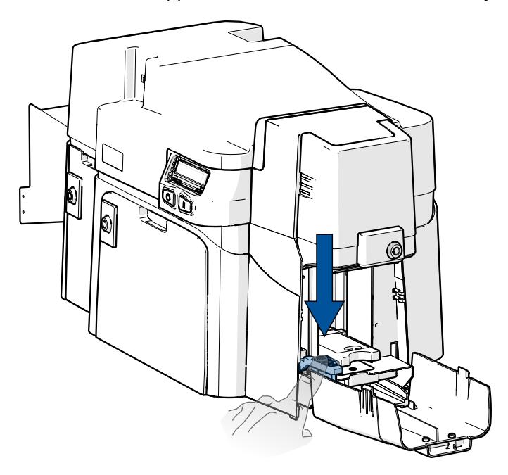
6. Load up to 100 cards into the lower hopper with the print side down.
Note: If using cards with a magnetic stripe, the magnetic stripe should be loaded with the stripe upand to the front of the printer.

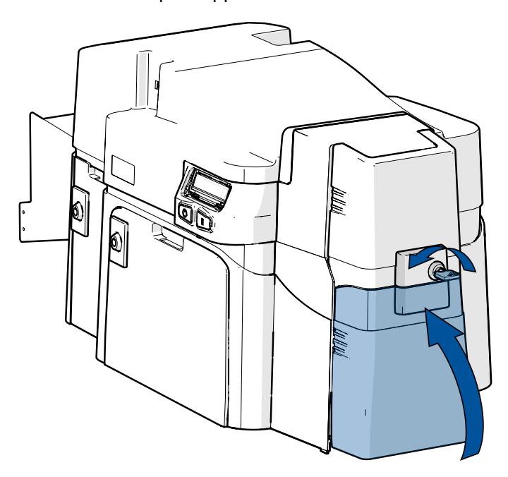
7. Close the dual input hopper lower door to release the lever to the printing position.
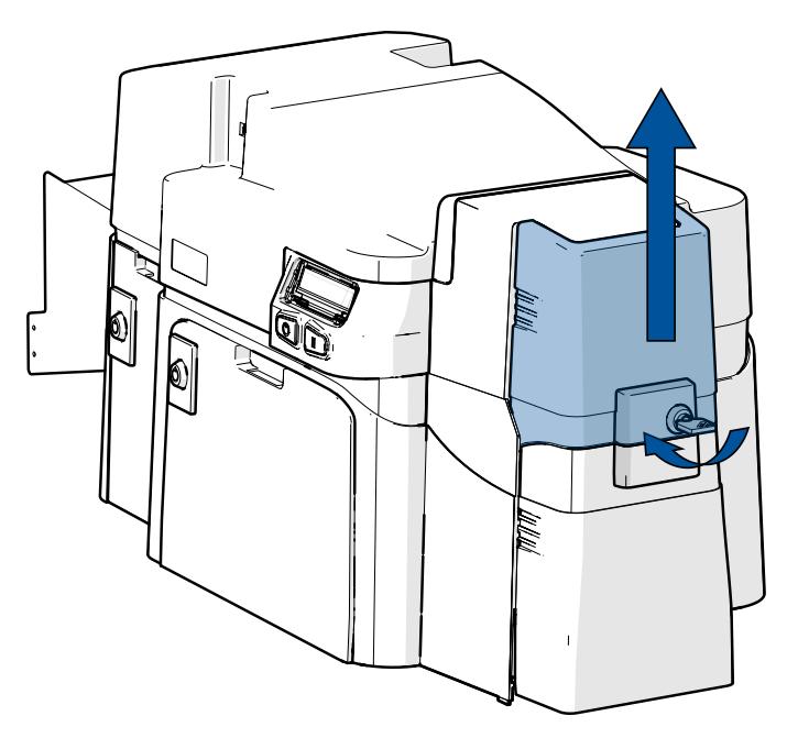
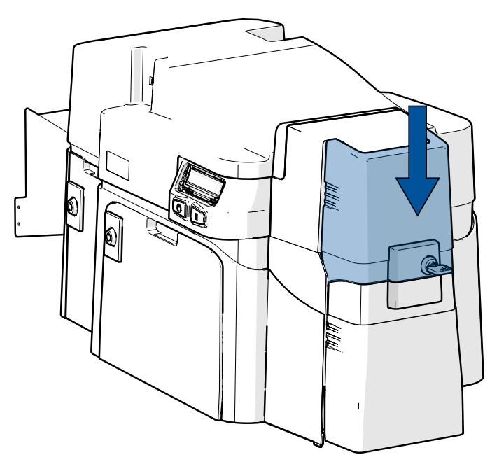
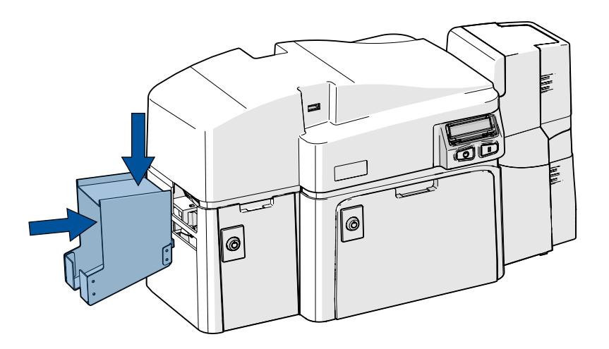
2.5 Installing the output hopper
Place the card output hopper into the bottom slot on the left side of the printer, push down until it locks into place.

2.6 Connecting the printer power
To connect power to the printer, follow this procedure.
Note: Do not connect a USB cable to the front of the printer. The USB connection on the front of the printer is for security connections only.
- 1. Plug the Ethernet cable into the back of the printer.
- 2. Plug the AC adapter power cable into the back of the printer.
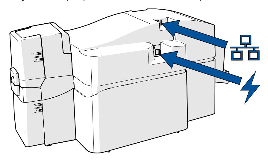
- 3. Plug the wall power cable into the AC power adapter.
- 4. Plug the wall power cable into a standard 100-240 V AC power outlet.
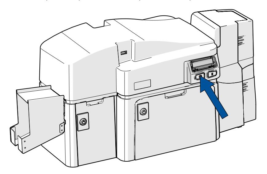
- 5. Press the printer's power button to power on the printer.
Note: The printer powers down during the "sleep time" but automatically powers up when a print job is sent.

2.7 Locking system
The printer includes additional security with the inclusion of locks on the following components:
- l Card input
- l Reject hopper
- l Material door
A set of two identical keys are provided that unlock all sections of the printer. In the event that these keys are misplaced, please contact HID Customer Services.
2.8 Accessory procedures: using the security lock slot
The printer has a security lock slot located in the back lip of the metal chassis to accommodate a standard laptop security lock.
To prevent unauthorized removal of the printer, attach an industry standard security cable to an immovable object and then lock the cable to the security lock slot.
The lock slot has a plastic covering that needs to be penetrated by the lock.
Note: Push the lock end into the slot with adequate force to break the protective film.
Follow the locking procedure recommended by the lock vendor.
Section 03 Cleaning and maintenance procedures


3.1 Cleaning and maintenance procedures
Use the following links to view cleaning and maintenance procedures for the DTCii Plus printer:

Clean card printer using adhesive card https://player.vimeo.com/video/730303403

Clean card printer using IPA card https://player.vimeo.com/video/730304212

How to calibrate the ribbon sensor https://player.vimeo.com/video/730305724

How to check the printer IP and MAC address https://player.vimeo.com/video/730306248

How to clean the print head https://player.vimeo.com/video/730306775


How to load cards and ribbon into the printer https://player.vimeo.com/video/730307330
Section 04 System overview - troubleshooting


4.1 Sequence of operations
Knowing the sequence of the printer operation helps when troubleshooting the printer.
- 1. File information is received from the PC.
- 2. Printer compares the installed ribbon type stored in memory with the ribbon type command that was sent from the printer. If the ribbon type does not match, the Pause button (on the right) flashes.
- 3. The print stepper motor engages.
- 4. The card feed sensor detects the leading edge of the card and the headlift stepper engages to disengage the input lever.
- 5. The card feeds through for the alignment pass.
- 6. The card feed stepper motor engages to queue card for magnetic encoding (if applicable).
- 7. The encoded data is written to the card (if applicable).
- 8. The magnetic encoder verifies while the stepper reverses the card (if applicable).
- 9. The print ribbon drive engages (if not already at the yellow panel).
- 10. The print ribbon sensor looks for the yellow panel.
Note: The print ribbon encoder detects the number of revolutions required to use an entire color panel.
- 11. The print stepper motor engages.
- 12. The card feed sensor detects the leading edge of card.
- 13. The print stepper motor queues card to the middle of the platen roller. All stop.
- 14. The print headlift motor engages to the print position.
- 15. The print cover sensor checks for closed state.
- 16. The print stepper motor engages.
- 17. The ribbon drive motor engages.
- 18. The image data is burned by the printhead until the image data is depleted. All Stop.
- 19. The thermistor engages the printhead cooling fan to maintain proper operating temperature.
- 20. The headlift motor engages to the queue position.
- 21. The print stepper motor engages.
- 22. The print ribbon drive engages.
- 23. After ribbon advances a few encoder clicks, assume the ribbon is free of card. All stop.
- 24. Repeat Steps 9 through 22 for the appropriate number of color/overlay Panels.
- 25. Either the card is ejected from the singled-sided printer or the card feed stepper engages to queue the card for the flipper table for the dual-sided printer.
- 26. All stop.

4.2 Troubleshooting
4.2.1 Printer error buttons
All printers have two buttons.

ON/OFF

Pause
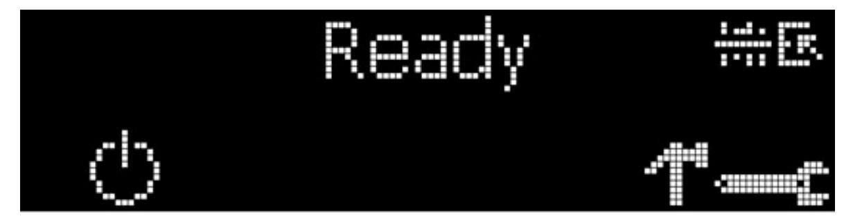
The display message system appears as a graphical message, for example:
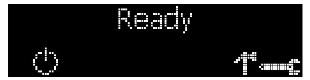
4.2.2 Error messages
This section provides the troubleshooting table for the error messages. When an error occurs in the printer, the PC shows the error message on screen with solutions.
Each table uses a 3-column presentation to display a specific error message, the cause, and the solution.
- l This format allows the troubleshooter to identify the error and its cause, and then perform the procedure provided in the solution column.
- l This standard mode of identifying the problem and its solution should provide an efficient method of troubleshooting this printer.
- l If you encounter problems beyond the capabilities of this error message table, you should contact Technical Support.
| Error message | Cause | Solution |
|---|---|---|
|
# 81
Unable to Feed |
The printer is unable to feed a
card from the input card hopper. |
Check the following:
Verify the card thickness setting is set to the thickness of your cards. l Verify the cleaning roller is properly installed on the ribbon cartridge. l Check for card slippage. If necessary, run the printer cleaning routine. l Verify that your cards are within the accepted card size range. l Verify the cards are not sticking together. l |

4.2.3 Troubleshooting with the error message table
| Error Message | Cause | Solution |
|---|---|---|
| # 2 | The print head lift has | Reset the printer and try again. |
| Head Move Error | malfunctioned. | If this problem persists, call for technical assistance. |
|
# 8
Head Sensor Error |
The print head temperature
sensor is not functioning or is not connected properly. |
Reset the printer and try again.
If the problem persists, call for technical assistance. |
|
Or, the print head is not cooling
properly. |
||
|
# 9
Reboot Required |
An unspecified system error has
been detected by the printer firmware. |
Reset the printer and try again.
If this problem persists, call for technical assistance. |
|
# 25
Ribbon not Installed |
No ribbon is installed in the
printer. |
Install a ribbon and retry. |
|
# 30
Mag Verify Error |
Magnetic encoding verification
has failed. |
Verify cards are oriented correctly.
Try encoding with a different card. Verify cards have the magnetic stripe. Replace the magnetic encoding module. |
|
# 31
No Mag Module |
The printer is not configured with
the encoder data type that you are trying to send. |
Ensure that no encoding data is being sent with the print job and reprint the
card. Install a magnetic encoding module. |
|
# 38
# 39 # 40 EEPROM Corrupt EEPROM Read Error |
EEPROM is restored with factory
default values. |
Reset the printer and try again. If this problem persists, call for technical
assistance. |
|
# 44
Flipper Jam/ Home Error |
A card has become jammed in
the printer flipper table. The flipper failed to position properly while aligning a card or flipping a card. |
Clear any cards in the flipper table using the buttons to move the card out.
Resume printing. The flipper table should be level when the printer is powered up. If the flipper Table is at an angle, open the card output door and manually level it. Then cycle the printer power to reset. Reset the printer and retry. If problem persists call for technical assistance. |
|
# 45
No Flip Module installed |
Request to print on 2nd side of
card, but no flipper is installed. |
Reset the printer and try again. If this problem persists, call for technical
assistance. |
|
# 64
# 65 # 66 Reboot Required |
Unspecified system error
detected by the printer firmware. |
Reset the printer and try again.
If this problem persists, call for technical assistance. |
|
# 68
Card in Printer |
A card is jammed in the print
station or card flipping area of the printer. |
Clear the jam and reset the printer. |

| Error Message | Cause | Solution |
|---|---|---|
|
# 70
Multiple Feed |
Multiple cards were fed into the
printer. |
Verify the card thickness is set to the thickness of your cards.
Check for card slippage. If necessary, run the printer cleaning routine. Verify the cleaning roller is properly installed on the ribbon cartridge. Verify the cards are not sticking together. |
|
# 81
Unable to Feed |
The printer is unable to feed a
card from the input card hopper. |
Check the following:
Verify the card thickness setting is set to the thickness of your cards. l Verify the cleaning roller is properly installed on the ribbon cartridge. l Check for card slippage. If necessary, run the printer cleaning routine. l Verify that your cards are within the perimeters accepted card size l range. Verify the cards are not sticking together. l |
|
# 82
Mag Jam |
A card is jammed in the
magnetic station |
Clear any cards in the magnetic station using the buttons to move the card
out. |
|
# 91
Ribbon Out |
The print ribbon has run out. | Install a new ribbon. |
|
# 93
Wrong Ribbon |
The print ribbon installed in the
printer does not match the ribbon type selected. |
Change either the installed print ribbon or the ribbon type. |
|
# 97
Ribbon Search Error |
The ribbon is not able to find the
next panel correctly. Check for jams/breaks. |
Recalibrate the ribbon sensor.
If broken, repair by taping the ribbon back on to the take- up core. Replace the ribbon. |
|
# 99
Ribbon Error |
The print ribbon has either
broken or jammed. |
If jammed, clear the jam.
If broken, repair by taping the ribbon back on to the take-up core. |
|
# 100
Ribbon RFID Error |
There is no ribbon or the ribbon
tag information is corrupted or incorrect. |
Verify the printer settings for correct ribbon.
Try a new ribbon and continue. |
|
# 102
# 103 # 104 #3 Headlift Error |
This is a problem with the
printhead lift. |
Reset the printer and try again.
If this problem persists, call for technical assistance. |
|
# 106
Job Data Error |
The print data sent to the printer
is corrupt or has been interrupted. |
Check the interface cable. |
|
# 107
Printing Error |
An error was detected during
printing. |
Reset the printer and try again.
If this problem persists, call for technical assistance. |
|
# 109
# 113 Ribbon Release Error |
The printer cannot locate the
next ribbon panel in order to release the ribbon from the card. |
Ensure that the ribbon is not stuck to the card.
Replace the ribbon. Recalibrate the ribbon sensor. If the ribbon is broken, repair by taping the ribbon back onto the take-up core and manually advance to the next panel. |

| Error Message | Cause | Solution |
|---|---|---|
|
# 110
Card Jam/Align error |
A card is jammed in the print
station or card flipping area of the printer. |
Clear the jam. |
|
# 111
Head Loading |
An unrecoverable error has
occurred during printing. |
Reset the printer and try again. If this problem persists, call for technical
assistance. |
|
# 112
Card Jam/Align error |
A card is jammed in the print
station or card flipping area of the Printer. |
Clear the jam. |
|
# 128
# 170 Calibrate Ribbon |
The print ribbon sensor is out of
calibration or has failed. |
Calibrate the ribbon sensor.
Check for material blocking sensor and try again. |
|
# 131
Flipper Jam/Home Error |
A card has become jammed in
the printer's flipper table. The flipper failed to position properly while aligning a card or flipping a card. |
Clear any cards in the flipper table, using the buttons to move the card out.
Resume printing. Reset the printer and retry. If problem persists call for technical assistance. |
|
# 139
Please Remove Ribbon |
Ribbon needs to be removed. |
Reset the printer and retry.
If problem persists, call for technical assistance. |
|
# 144
EEPROM Corrupt EEPROM Read Error |
EEPROM restored with factory
default values. |
Reset the printer and try again. If this problem persists, call for technical
assistance. |
|
#202
Encoder not installed |
You are trying to send encoding
data, but the printer is not configured with this encoder type. |
Ensure that no encoding data is being sent with the print job and reprint the
card. Install an encoding module. |
| Card in Printer |
There was a card in the printer at
boot up or cover close when no job is active. |
Open the cover, remove the card, and close the cover. |
| Check Ribbon |
The ribbon could not be queued
to the first panel of the set. |
Recalibrate the ribbon sensor. If broken, repair by taping the ribbon back to
the take-up core. |
| Empty Reject Bin |
The reject bin needs to be
emptied. |
Open reject bin door, remove cards and press the OK button. |

4.2.4 Printer-specific tools
The status icons are as follows:

This icon indicates that the print ribbon supply is low and requires replacement soon.

This icon indicates that the printer needs to be cleaned.
Section 05 HID Global Technical Support


5.1 Before contacting HID Global Technical Support
- l Position a phone near the printer and computer so the Technician can help to troubleshoot the printer.
- l Have a self-test and a sample card ready when calling HID Global Technical Support.
5.2 Reading the serial numbers on a FARGO printer
To determine when the card printer was manufactured, see the serial number (affixed to the card printer).
Example: Serial Number C0050028 (2020)
- l The first two digits indicate the year the printer was built ( C0 indicates the year 2020).
- l The third and fourth digits indicate the week the printer was built ( 05 indicates week 5 of that year).
- l The last four digits indicate the sequence number for the numeric order in which the printers were built.
Contact the HID Global Technical Support Group :
Website: www.hidglobal.com/support

Revision history
| Date | Description | |
|---|---|---|
| August 2022 | Adds cleaning and maintenance instructions. Updates compliance information. | A.2 |
| December 2020 | Minor updates. | A.1 |
| September 2020 | Initial release. | A.0 |

For technical support, please visit: https://support.hidglobal.com
© 2022 HID Global Corporation/ASSA ABLOY AB. All rights reserved. PLT-05151, Rev. A.2
Part of ASSA ABLOY