HES K100 Series Wireless Cabinet Lock Installation Instructions
Open the original PDF document
View PDFHES K100 Aperio Series Wireless Cabinet Lock
Installation and Operating Instructions
Products Specifications
Wireless Frequency: 2.4GHz, IEEE 802.15.4, using AES 128-bit encryption
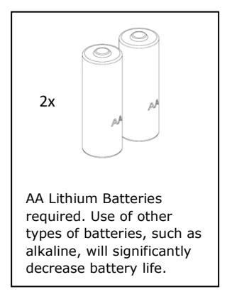
Lock Battery Type: AA Lithium, 1.5 Volts (V)
Battery Life: 50,000 cycles*
* All battery life claims are approximate and based on a set configuration profile. Battery performance is based on pre-defined system settings such as battery chemistry and battery model used, credential presentation settings (LED/buzzer), UHF polling period, UHF status intervals, and operations per day. Actual battery performance will vary and depends on the factors above.
Operating Temperature: 32 to 122 F (0 to 50 C)
HID® multiCLASS SE® technology Credentials Supported:
-
High Frequency (13.56 MHz):
- HID iCLASS®
- HID iCLASS SE® (SIO-enabled)
- HID iCLASS® Seos™
- HID MIFARE® SE
- HID DESfire® EV1 SE
- MIFARE CLASSIC
- DESfire® EV1
-
Low Frequency (125 kHz):
- HID Prox® , AWID, EM4102, ioProx
- NFC-enabled Mobile Phones
Recommended Tools
Flathead Drivers — 3/32", 3/16"
Drill, Drill Bits — 1/16", 3/16", 1/2"
Phillips Drivers — P0, P2
Pencil, Wire Stripper, Level, Square, Ruler, Punch, Scissors
Hardware Specifications
Table 1 – Shaft Length
| Door Thickness | Shaft Used |
|---|---|
| 1/16" – 1/2" | L1 |
| >1/2" - 1½" | L2 |
| >11/2" - 21/4" | L3 |
Table 2 – Mounting Screw Length for Various Door Thickness
|
Door
Thickness |
Reader
Mounting |
Cut to approx. screw length |
Lock
Mounting |
Cut to
Approx. Screw Length |
|---|---|---|---|---|
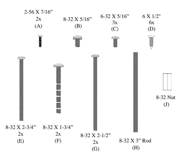
| 1/16" | Coupling Nut and 3" Rod | 10/16" |
8-32 x 1-3/4"
Break Away |
1-1/16" |
| 1/4" | Coupling Nut and 3" Rod | 13/16" |
8-32 x 1-3/4"
Break Away |
1-1/4" |
| 1/2" | Coupling Nut and 3" Rod | 1-1/16" |
8-32 x 1-3/4"
Break Away |
1-7/16" |
| 3/4" | Coupling Nut and 3" Rod | 1-5/16" |
8-32 x 1-3/4"
Break Away |
No Cut |
| 1" | Coupling Nut and 3" Rod | 1-9/16" | 8-32 x 2-1/2" | 2" |
| 1-1/4" | Coupling Nut and 3" Rod | 1-13/16" | 8-32 x 2-1/2" | No Cut |
| 1-1/2" | Coupling Nut and 3" Rod | 2-1/16" | 8-32 x 2-3/4" | No Cut |
For Technical Support Please call 1-800-810-WIRE
Package Contents
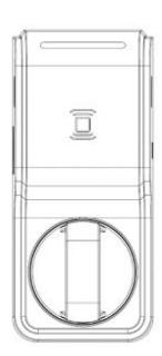
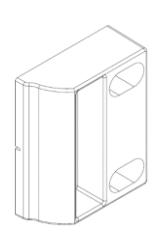
Reader Lock Body
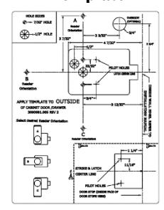
Installation Template
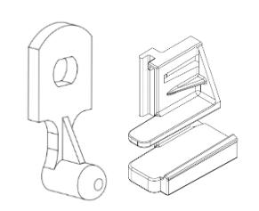
Strike Plate
Mechanical Key Override
Threadlock Pillow Pack
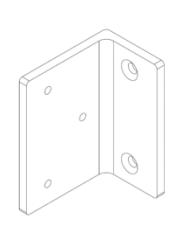
Double Door Bracket
Hardware
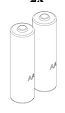
Lithium Batteries 2x
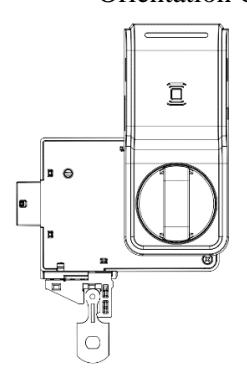
Lock Orientation Options
Orientation A Orientation B
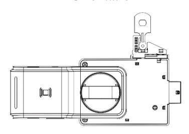
Orientation C
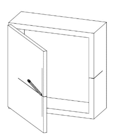
Prepping the Cabinet/Drawer Face
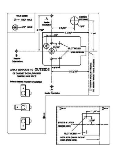
1. Separate Strike Plate Template. 2. Establish centerline (for double door cabinet prep go to page 6).
-
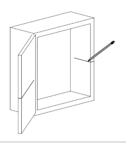
3. Measure cabinet wall thickness and mark offset line on face of cabinet/drawer. The offset line should match with the interior edge of the cabinet wall.
- 4. Continue centerline to face of cabinet/drawer
-
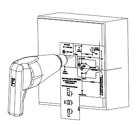
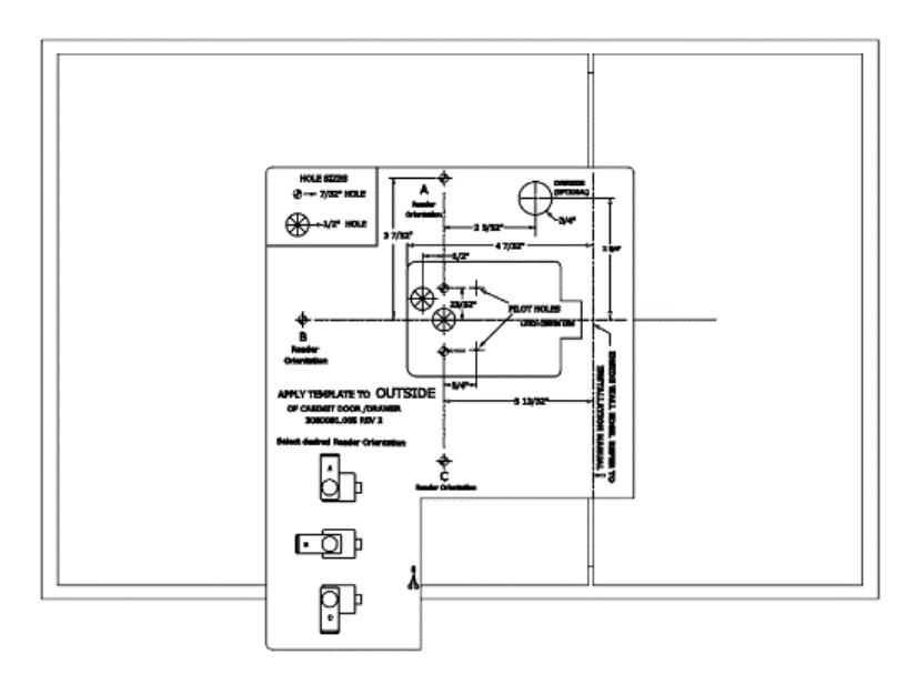
5. Align template to offset line and centerline. Remove backing and apply template onto cabinet/drawer face.
- Center line Offset Line
6. Use punch to mark drilling locations then drill mounting holes. If using mechanical key override, drill key override hole as well.
Prepping the Cabinet/Drawer Face (Double Door)
- 1. Establish center line on inside of stationary door.
- 2. Continue center line onto outside face of cabinet.
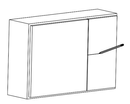
3. Align offset line on template to the edge of the stationary door and align center line with the established center line above. Remove backing and apply template to cabinet face. Continue with Step 6 in previous section.
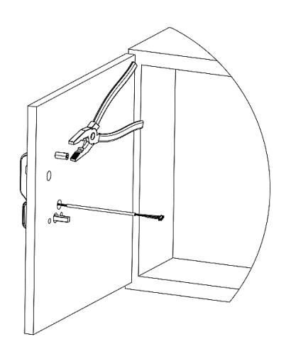
Reader Installation
-
1. Align reader with mounting holes and pull cable through as shown. Trim Threaded rod to length as outlined in table 2.
- 2. Add Threadlock to threaded rod. Secure Reader to cabinet/drawer using the cut threaded rod and coupling nut. DO NOT overtighten.
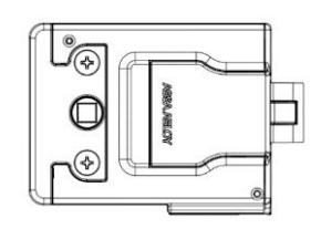
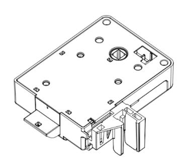
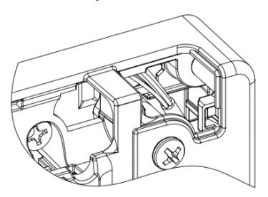
Mechanical Override (Optional)
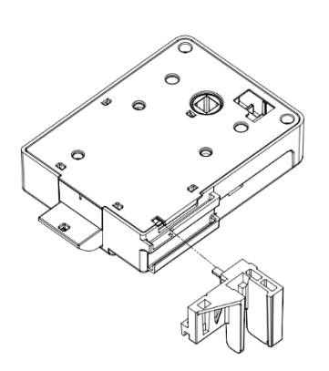
1. Slide Override into slot as shown. 2. Ensure that override retracts latch bolt before installation. Override should rest loosely until lock body and battery cover are installed.
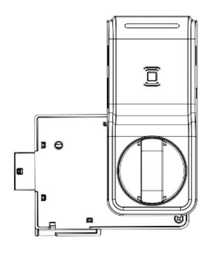
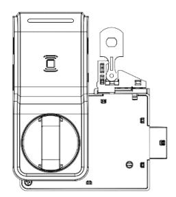
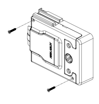
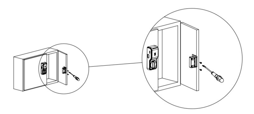
Lock Body Installation
1. Insert reader cable through hole in back of lock body.
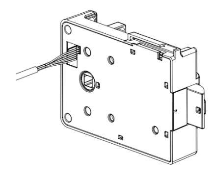
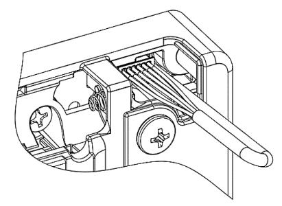
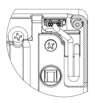
5. Any excess cable should be inserted into the cavity as shown below.
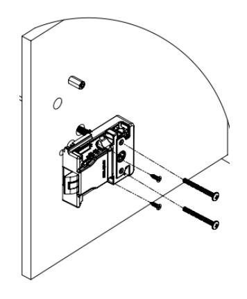
2. Align lock body to mounting holes andsecure to cabinet/drawer face using 2x screw F and 2x screw D. If thick cabinet/drawer then use 2x screw E or 2x screw G instead of 2x screw F. DO NOT over tighten.
3. Plug cable into slot on lock body. 4. Tuck excess cable into lock body cavity as shown.
6. For cabinet/drawer face thicker than1/2", add a third screw D as shown.
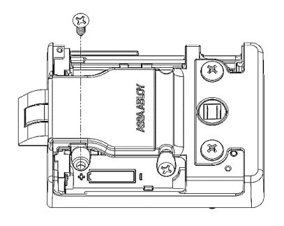
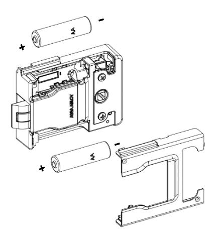
Installing the Batteries
- 1. Install AA lithium batteries in appropriate position.
- 2. Install cover and secure using 2x screw A.
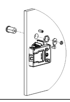
Mechanical Key Override (Optional)
Mechanical key override cam lock sold separately.
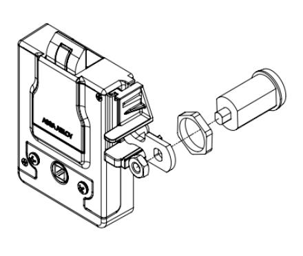
1. Insert cam lock through the outside of the cabinet/drawer face and secure with locking nut. Insert the end of Cam into the mechanical override and secure with nut as shown.
Important Note – Reader MUST be programmed before installing the strike plate. If the cabinet is closed before the reader is programmed and after the strike plate is installed, you will be locked out of the cabinet.
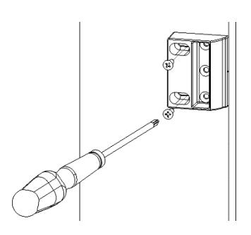
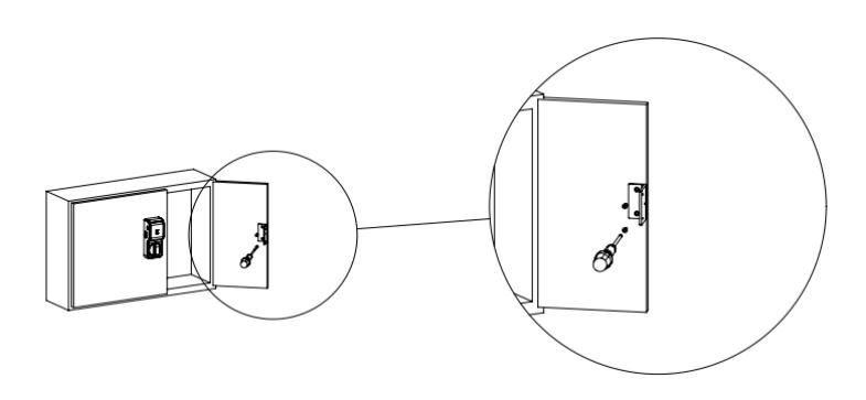
Strike Plate Installation
1. Align strike plate template to centerline and edge of cabinet. Drill mounting holes.
2. Secure strike plate to inside cabinet wall using 2x screw D, but do not fully tighten. Adjust strike plate so the edge is flush with the cabinet wall edge then tighten.
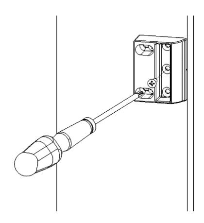
3. After the strike plate is in the desired position, fasten screw D into strike plate as shown below.
Double Door Strike Installation
1. Align Double door bracket with mounting holes from the strike plate template. Secure double door bracket using 3x screw D.
2. Secure strike plate to double door bracket using 3x screw D as shown below.
Page 11 of 16 For more information visit website assaabloyesh.com P/N: 3080006.016 Rev1
LED Codes
| ASSA ABLOY One yellow flash | rio LED LOCK Cod | les: Card read aperio |
|---|---|---|
| One green flash | Access granted | |
| Five yellow, one red flash | Force closed (in open mode) | |
| Continous yellow flashes (.25 sec every second) | Comhub busy | |
| One red flash | Access denied (AC online) | |
| Three red flashes | Access denied (AC offline) | |
| Continous red flashes (.125 sec every second) | Lock is blocked (when closing) | |
| Ten red flashes | Error in Lock | |
| Continous yellow flashes (.25 sec every 5 seconds) | Low Battery | |
| Continous red flashes (.25 sec every 5 seconds) | Dead Battery |
Aperio Hub
Technical Data – AH20
| Approvals | CE, ETL, FCC, IC, C-Tick |
|---|---|
| Safety and emissions |
FCC 47CFR Part 15 subpart
B and subpart C; IC RSS-210 EN ETSI 301 489-17 v2.1.1; ENETSI 300 328 v1.7.1; EN 60950-1 ed.2 2007 |
| Dimensions | 82x82x37 |
| Power Supply | 8-24 VDC |
| Current | 250 mA minimum |
| Internal Antenna | 2cross polarized dipoles |
|
External Antenna
(Part No. EXT-10-ANT) |
One reverse polarity SMA
external antenna connector. Optional antenna type dipole with max antenna gain of 3.9dBi |
| Radio Standard |
IEEE 802.15.4(2.4GHz) –
15 channels (11-25) |
|
Encryption (Radio
Communications) |
AES 128 bits |
| Wireless Operating Range | Up to 50 ft |
| Receiver Sensitivity | 100dBm 20%PER |
| Wireless Transmit Power | 10 dBm/MHz |
| Class of Protection | IP 20 |
| Operating temperature range | 5°C to 35°C |
| Humidity | < 95% non-condensing |
| Status | LED (red/green/orange) |
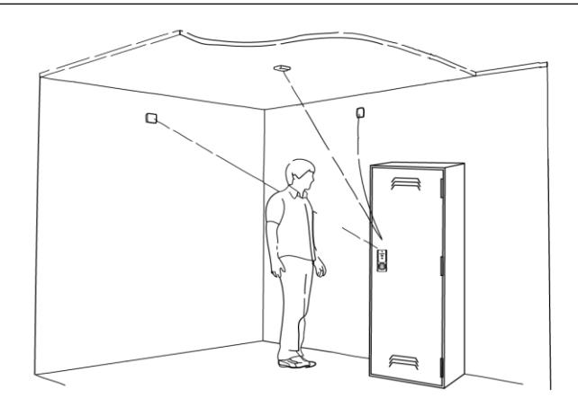
Connecting the Hub
The following applies only to Aperio factory paired kits with AH20 Hubs.
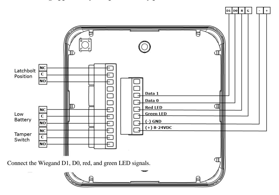
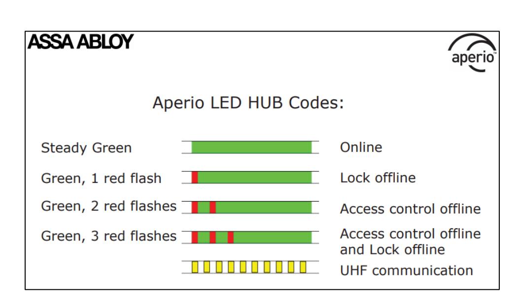
Note: The Green LED input is used to grant access to the cabinet lock. If the Green LED signal is not available to indicate approved access, the approval input can be activated by a relay with "NO" attached to Green LED and "C" to GND.
The Red LED input is used to indicate access denied. If the RED LED signal is not connected, the lock will flash RED three times when a non-approved card is presented indicating loss of connection to the hub rather than access denied. Any other codes may be reference on the LED reference card.
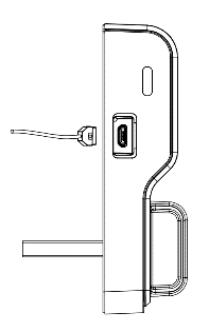
Micro USB Port
For Emergency Power & Local (Hard Wired) Firmware Updates, use micro USB port located on the side of the K100
FCC Statement
This equipment has been tested and found to comply with the limits for a class B digital device, pursuant to part 15 of the FCC Rules. These limits are designed to provide reasonable protection against harmful interference in a residential installation. This equipment generates, uses, and can radiate radio frequency energy and if not installed and used in accordance with the instructions, may cause harmful interference to radio communications. However, there is no guarantee that interference will not occur in a particular installation. If this equipment does cause harmful interference to radio or television reception, which can be determined by turning the equipment off and on, the user is encouraged to try to correct the interference by one or more of the following measures:
- 1. Reorient or relocate the receiving antenna.
- 2. Increase the separation between the equipment and receiver.
- 3. Connect the equipment into an outlet on a circuit different from that to which the receiver is connected.
- 4. Consult the dealer or an experienced radio/TV technician for help.
Operation with non-approved equipment is likely to result in interference to radio and TV reception. The user is cautioned that changes and modifications made to the equipment without the approval of manufacturer could void the user's authority to operate this equipment.
IC Statement
This device complies with Industry Canada license-exempt RSS standards(s). Operation is subject to the following two conditions:
- (1) this device may not cause interference, and
- (2) this device must accept any interference, including interference that may cause undesired operation.
Conformité aux normes FCC
Cet équipement a été testé et trouvé conforme aux limites pour un dispositif numérique de classe B, conformément à la Partie 15 des règlements de la FCC. Ces limites sont conçues pour fournir une protection raisonnable contre les interférences nuisibles dans une installation résidentielle. Cet équipement génère, utilise et peut émettre des fréquences radio et, s'il n'est pas installé et utilisé conformément ment aux instructions du fabricant, peut causer des interferences nuisibles aux communications radio. Rien ne garantit cependant que l'interférence ne se produira pas dans une installation particulière. Si cet équipement provoque des interférences nuisibles à la réception radio ou de télévision, qui peut être déterminé en comparant et en l'éteignant, l'utilisateur est encouragé à essayer de corriger les interférence par une ou plusieurs des mesures suivantes:
- 1. Réorienter ou déplacer l'antenne de réception.
- 2. Augmenter la distance entre l'équipement et le récepteur.
- 3. Branchez l'appareil dans une prise sur un circuit différent de celui auquel le récepteur est connecté.
- 4. Consultez votre revendeur ou un technicien radio / TV pour assistance.Avertissement
Les changements ou modififications à cet appareil sans expressément approuvée par la partie responsable de conformité pourraient annuler l'autorité de l'utilisateur de faire fonctionner cet équipement.
Conformité aux normes IC
Cet appareil est confrome avec Industrie Canada exempt de license RSS standard(s). Son fonctionnement est souimes aux deux conditions suivantes:
- (1) cet appareil ne peut causer d'interférences, et
- (2) cet appareil doit accepter toute interference, y compris des interférences qui peuvent provoquer un fonctionnement indésirable du périphérique.