HES 9800 Series Installation Instructions
Open the original PDF document
View PDFHES® 9800 | Adams Rite® 7800 Electric Strike
ASSA ABLOY
The global leader in door opening solutions
Installation Instructions and Frame Preparation
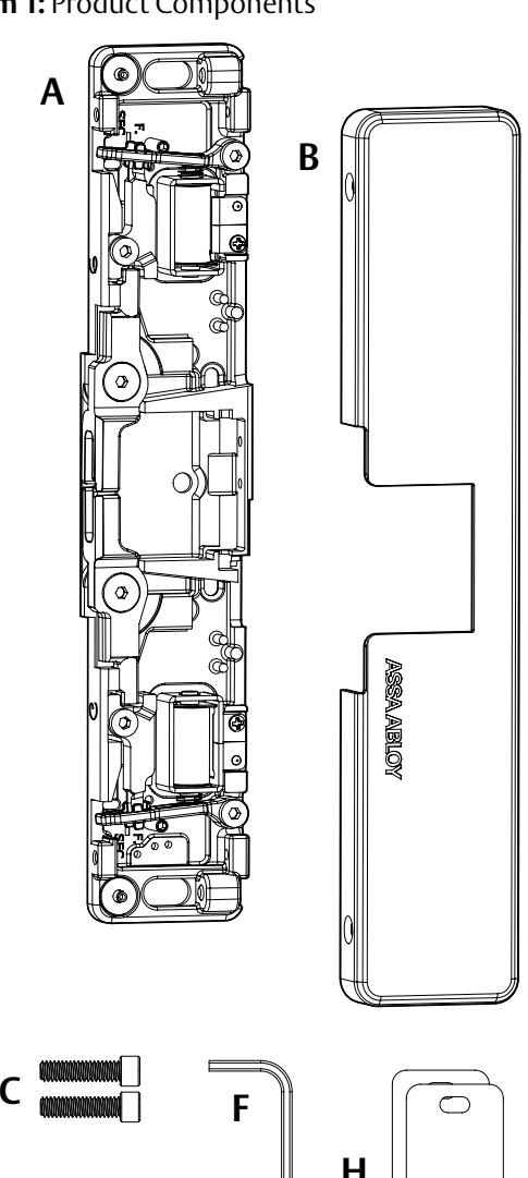
Product Components
A HES 9800 | Adams Rite 7800 Strike Body
B HES 9800 | Adams Rite 7800 Cover
C 1/4"-20 x 1" Mounting Screws
D #10-32 & 10-24 Lockdown Screws (optional)
E #6-32 x 1/4" Cover Screws
F 5/64" Hex Key
G 12-Volt and 24-Volt Pigtails
H 1/8" and 1/16" Spacers
Electrical Specifications
| Electrical Ratings for Solenoid | |||
|---|---|---|---|
| Voltage | 12 VDC | 24 VDC | |
| Resistance in Ohms | 24 | 96 | |
| mA Continuous Duty | 450 | 250 | |
Solenoids are rated at +/- 10% indicated value.
|
Minimum Wire Gauge
Requirements (Based on Round Trip) |
Solenoid Voltage | |
|---|---|---|
| 12 VDC | 24 VDC | |
| 200 feet or less | 18 gauge | 22 gauge |
| 200 – 300 feet | 16 gauge | 22 gauge |
| 300 – 400 feet | 16 gauge | 20 gauge |
UL1034
- Static Strength: 1500 lbs
- Dynamic Strength: 70 ft lbs
- Endurance: 250,000 cycles
UL294 Performance Levels
- Destructive Attack: Level I
- Line Security: Level I
- Endurance: Level IV
- Standby Power: Level I
Diagram 1: Product Components
CAUTION Before connecting any device at the installation site, verify input voltage using a multimeter. Many power supplies and low voltage transformers operate at higher levels than listed. Any input voltage exceeding 10% of the solenoid rating may cause severe damage to the unit and will void the warranty.
Preparing the Strike
For 12 VDC, the Plug In Connector (pigtail) marked "12 VDC" should be used; for 24 VDC, the pigtail marked "24 VDC" should be used.
- SELECT the appropriate pigtail that matches system power and electrically CONNECT as illustrated in Diagram 1.
- IF no connector is present, THEN CONFIGURE the wires as shown in Diagram 2.
- IF using the Latchbolt Monitor (LBM) or Latchbolt Strike Monitor (LBSM), THEN REFER to Diagrams 5 and 6 to complete wiring (see page 3).
Verifying the Operation Mode
The HES 9800 | Adams Rite 7800 Electric Strike is pre-set for FAIL SECURE OPERATION as shown in Diagram 3.
• VERIFY that both keepers are in FAIL SECURE OPERATION.
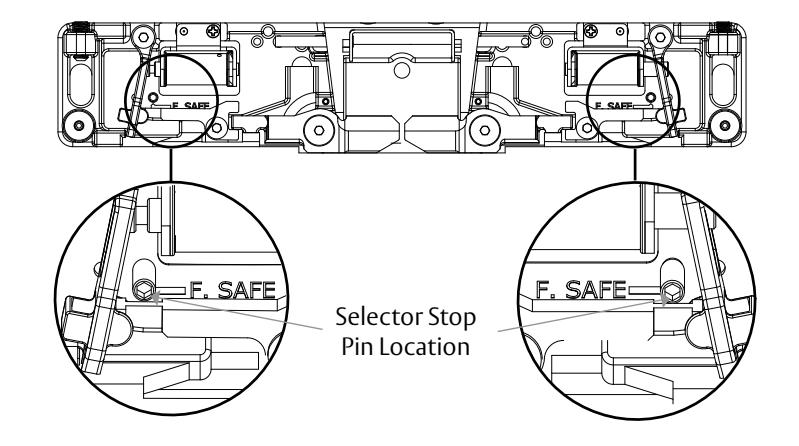
Converting the Operation Mode
There are two Selector Stop Pins, one on the left side and one on the right side. Both Selector Stop Pins must be repositioned (as shown in Diagram 4) to convert the strike to FAIL SAFE OPERATION.
IN FAIL SAFE OPERATION: Both keepers should be unlocked without power but locked when power is applied.
- To convert to FAIL SAFE OPERATION, REMOVE the Selector Stop Pins on each side of the strike body using the provided 5/64" hex key.
- MOVE the Selector Stop Pins to the FAIL SAFE OPERATION position (towards the center of the strike) as shown in Diagram 4.
- TIGHTEN both Selector Stop Pins after they have been moved to the FAIL SAFE OPERATION position using the 5/64" hex key.
FAIL SAFE OPERATION mode should not be used in fire rated or windstorm-resistant applications.
Diagram 1: 12V to 24V Conversion Diagram 2: If Connector Is Missing
Red/green Violet Red Black Violet Red/green (+ 12 VDC) (- NEG) (+ 24 VDC) (- NEG) or Electric Strike Electric Strike Connect Together Connect Together Connect Together
Diagram 3: Fail Secure Operation
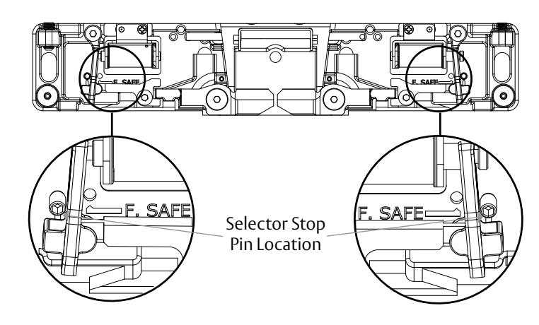
Diagram 4: Fail Safe Operation
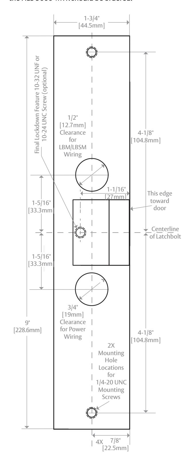
Preparing the Frame
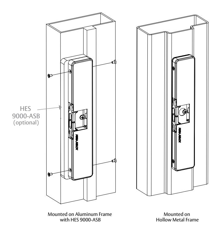
When mounting on an aluminum frame, with a blade stop, an HES 9000-ASB (sold separately) is necessary to provide a secure installation. The HES 9000-ASB is shown installed in Diagrams 8 and 9.
- IDENTIFY and MARK the latchbolt centerline on the frame.
- Using the dimensions provided on page 4, MARK all appropriate holes. If using a HES 9000-ASB, reference the installation instructions provided with that product. NOTE: This may require the exit device to shift horizontally towards the hinge side of the door to compensate for the HES 9000-ASB.
- PUNCH, DRILL and TAP the marked holes as required.
Finishing the Installation
- ELECTRICALLY CONNECT the HES 9800 | Adams Rite 7800 to the Plug In Connector, and ATTACH the electric strike to the jamb using the 1/4"-20 x 1" mounting screws provided.
- CHECK the starwheel interaction with the keepers to ensure proper engagement and clearance. The starwheel's latchguard needs to be centered within the keepers as seen in Diagram 7. If horizontal adjustment is needed, use one or both of the spacers to provide latch guard/keeper clearance. Additional spacers can be ordered separately.
Adjusting Horizontal and Lockdown
- TIGHTEN the two 1/4"-20 x 1" mounting screws.
- SECURE the adjustment by tightening the set screws. Shown in Diagram 8 on page 4.
- OPTIONAL LOCKDOWN FEATURE: INSTALL the #10-24 UNC or 10-32 UNF lockdown screw if additional security is required; however, REMOVE the strike before drilling hole. If using a HES 9000-ASB it will require drilling and tapping of the lockdown hole.
- INSTALL the cover plate, and SECURE in place using the #6-32 x 1/4" Cover Screws as illustrated in Diagram 9 on page 4.
Diagram 5 Latchbolt Monitor
| White | Common |
|---|---|
| Orange | Normally Open |
| Green | Normally Closed |
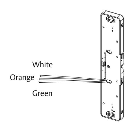
Diagram 6 Latchbolt Strike Monitor
| Brown | Common |
|---|---|
| Blue | Normally Open |
| Yellow | Normally Closed |
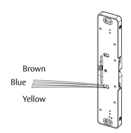
Diagram 7: Starwheel & Keeper Cross-section Latchguard should be centered between the keepers.
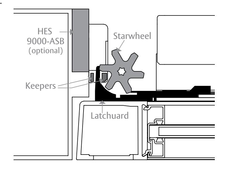
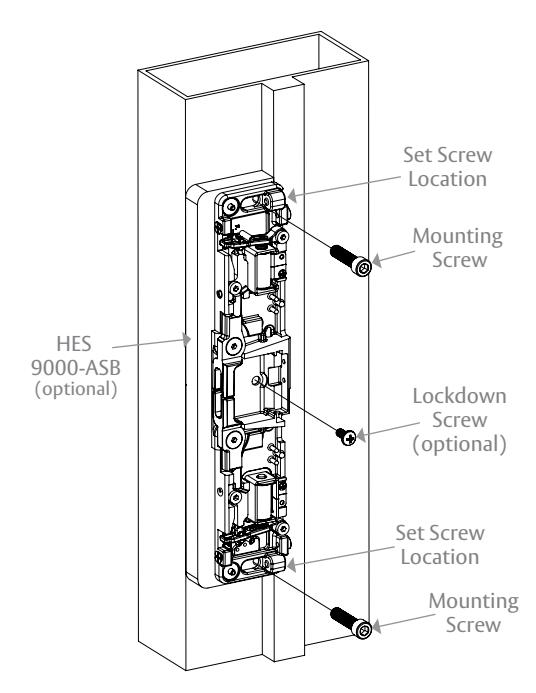
Diagram 9
Dimensions
NOTE: May not be to scale. For easy installation, the HES 9000-MTK should be ordered. Diagram 8