HES 9700 Series Electric Strikes Installation Instructions
Open the original PDF document
View PDFHES 9400/9500/9600 Electric Strike
Installation Instructions and Frame Preparation
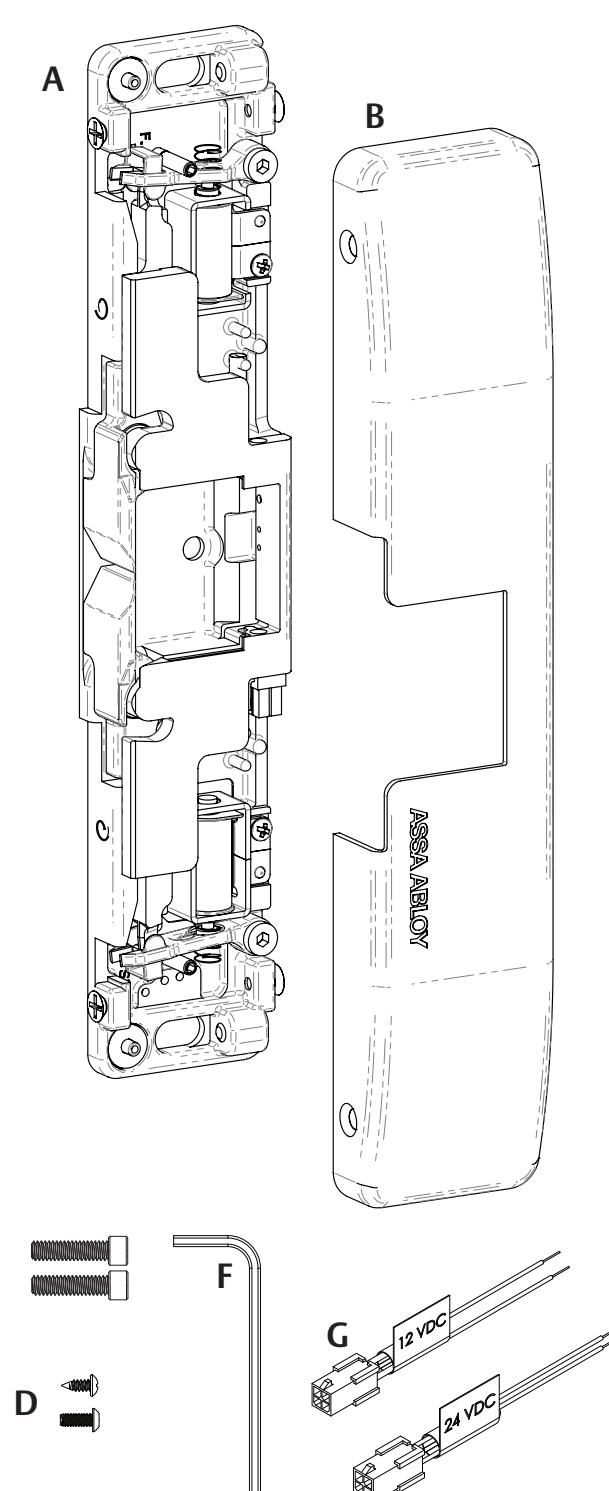
Product Components
A 9400/9500/9600 Strike Body
B 9400/9500/9600 Cover
C 1/4"-20 x 1" Mounting Screws
D #10-32 & 10-24 Lockdown Screws (optional)
E #6-32 x 1/4" Cover Screws
F 5/64" Hex Key
G 12-Volt and 24-Volt Pigtails
Electrical Specifications
| Electrical Ratings for Solenoid | |||
|---|---|---|---|
| Continuous Duty | 12 VDC | 24 VDC | |
| Resistance in Ohms | 24 | 96 | |
| Amps | .50 | .25 | |
Solenoids are rated at +/- 10% indicated value.
|
Minimum Wire Gauge
Requirements (Based on Round Trip) |
Solenoid Voltage | |
|---|---|---|
| 12 VDC | 24 VDC | |
| 200 feet or less | 18 gauge | 22 gauge |
| 200 – 300 feet | 16 gauge | 22 gauge |
| 300 – 400 feet | 16 gauge | 20 gauge |
Diagram 1: Product Components
C
E
Installation
CAUTION Before connecting any device at the installation site, verify input voltage using a multimeter. Many power supplies and low voltage transformers operate at higher levels than listed. Any input voltage exceeding 10% of the solenoid rating may cause severe damage to the unit and will void the warranty.
Preparing the Strike
NOTE: For 12 VDC, the Plug In Connector (pigtail) marked "12 VDC" should be used; for 24 VDC, the pigtail marked "24 VDC should be used.
- 1 SELECT the appropriate pigtail that matches system power and electrically CONNECT as illustrated in Diagram 2.
- 2 IF no connector is present, THEN CONFIGURE the wires as shown in Diagram 2.
- 3 IF using the Latchbolt Monitor (LBM) or Latchbolt Strike Monitor (LBSM), THEN REFER to Diagrams 3 and 4 on Page 3 to complete wiring.
NOTE 1: The 9400/9500/9600 ships in FAIL SECURE OPERATION mode.
NOTE 2: FAIL SAFE OPERATION mode should not be used in fire or windstorm-rated applications.
4 CONVERT the 9400/9500/9600 to FAIL SAFE OPERATION, if needed, using Diagrams 5 and 6 on Page 3 as a guide.
Preparing the Frame
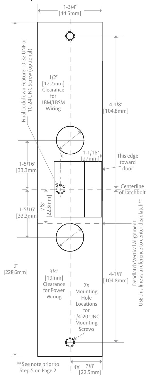
NOTE: When using a Corbin Russwin Series 5000 or Yale 7000 series equipped with an offset deadlatch, the deadlatch is located just above the Vertical Alignment line, as shown on the Installation Template on Page 4.
1 PREPARE the door jamb using the Installation Template located on Page 4 (with the exception of the hole for final lockdown).
Red Red/green Black Violet Red Black Violet Red/green (+ 12 VDC) (-NEG) (+ 24 VDC) (-NEG) or Electric Strike Electric Strike Connect Together Connect Together Connect Together Diagram 2: 12V to 24V Conversion If Connector Is Missing
Finishing the Installation
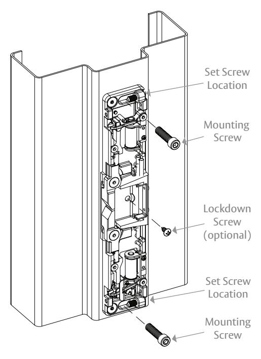
- 1 Electrically CONNECT the 9400/9500/9600 to the Plug In Connector, and ATTACH the electric strike to the jamb using the 1/4"-20 x 1" mounting screws provided.
- 2 CHECK latchbolt interaction to determine if horizontal adjustment is needed, and ADJUST as needed; then LOCK DOWN the horizontal adjustment using the #10-32 set screws as illustrated on Page 4.
- 3 OPTIONAL LOCKDOWN FEATURE: INSTALL the #10-24 UNC or 10-32 UNF lockdown screw if additional security is required; however, REMOVE the strike before drilling hole.
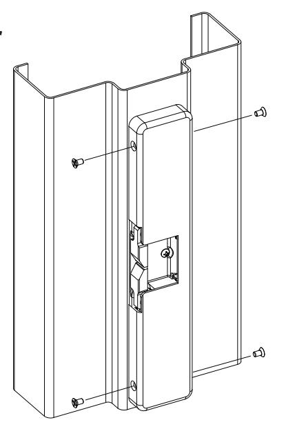
- 4 INSTALL the cover plate, and SECURE in place using the #6-32 x 1/4" Cover Screws as illustrated on Page 4.
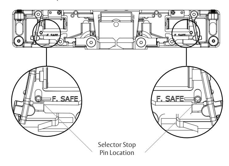
Converting the Operation Mode
NOTE 1: The 9400/9500/9600 series Electric Strikes are pre-set for FAIL SECURE OPERATION as shown in Diagram 5.
NOTE 2: There are Selector Stop Pins, one on the left side and one on the right side. Both Selector Stop Pins must be repositioned to convert the strike to FAIL SAFE OPERATION.
- 1 To convert to FAIL SAFE OPERATION, REMOVE the Selector Stop Pins on each side of the strike body using the provided 5/64" hex key.
- 2 MOVE the Selector Stop Pins to the FAIL SAFE OPERATION position (towards the center of the strike) as pictured in Diagram 6.
- 3 TIGHTEN both Selector Stop Pins after they have been moved to the FAIL SAFE OPERATION position using the 5/64" hex key.
Verifying the Operation Mode
NOTE: Both keepers should be unlocked without power, but lock when power is applied.
1 VERIFY that both keepers are in FAIL SAFE OPERATION.
Diagram 3 Latchbolt Monitor
| White | Common |
|---|---|
| Orange | Normally Open |
| Green | Normally Closed |
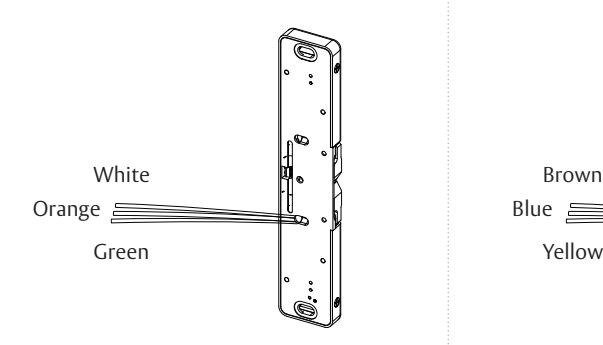
Diagram 4 Latchbolt Strike Monitor
| Brown | Common |
|---|---|
| Blue | Normally Open |
| Yellow | Normally Closed |
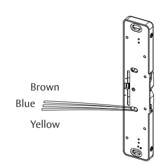
Diagram 5: Fail Secure Operation
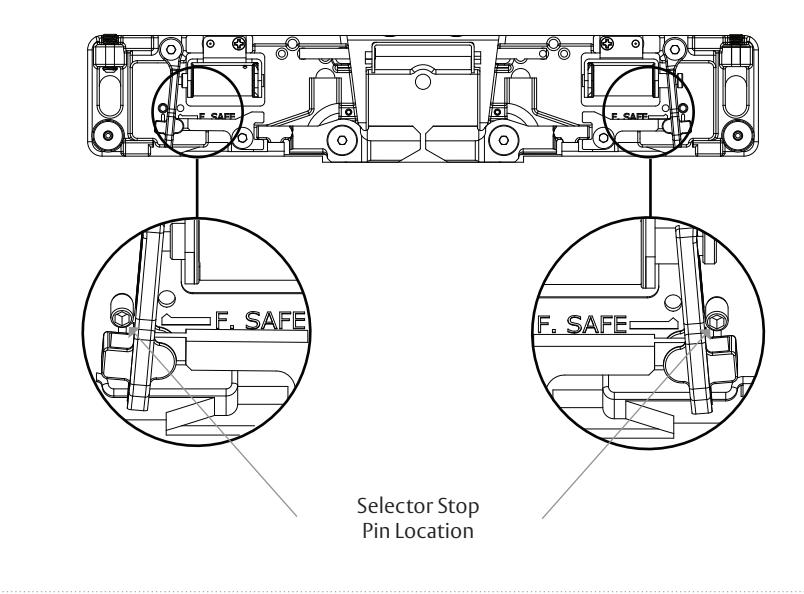
Diagram 6: Fail Safe Operation
Frame Preparation
Adjusting Horizontal and Lockdown
- 1 LOOSEN the two 1/4"-20 x 1" mounting screws.
- 2 ADJUST strike to appropriate horizontal position
- 3 TIGHTEN the two 1/4"-20 x 1" mounting screws
- 4 SECURE the adjustment by tightening the set screws
- 5 INSTALL the #10-32 UNF or 10-24 UNC lockdown screw (optional).
Installing the Cover
1 ATTACH the cover using the #6-32 x 1/4" Cover Screws
Template
NOTE: May not be to scale. For easy installation, the template should be ordered.
ELECTRONIC SECURITY HARDWARE
HES | Securitron
techsupport.esh@assaabloy.com | assaabloyesh.com 800.626.7590 | 10027 S. 51st Street Phoenix, AZ 85044 USA
3026006.002 rev D
Copyright © 2018, Hanchett Entry Systems, Inc., an ASSA ABLOY Group company. All rights reserved. Reproduction in whole or in part without the express written permission of Hanchett Entry Systems, Inc. is prohibited.