HES 8500 Series Electric Strike Installation Instructions
Open the original PDF document
View PDF

Installation Instructions 8500 Series Electric Strike
HES, Inc. Phoenix, AZ 800-626-7590 www.hesinnovations.com
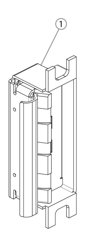
1
Product Components
- 1) 8500 Electric Strike Body
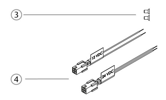
- (3) #4-40 Screws
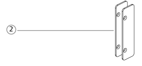
- (2) Horizontal Lockdown Shims
- (4) 12 & 24 Volt Pigtails
Electrical Specifications
| ELECTRICAL RATINGS FOR SOLENOID | CONTINUOUS DUTY | INTERMITTENT DUTY* | ||
|---|---|---|---|---|
| 12VDC | 24VDC | 12-16VAC | 24VAC | |
| Resistance in Ohms | 50 | 200 | 50 | 200 |
| Amps | .24 | .12 | .2432 | .12 |
Solenoids are rated at +/- 10% indicated value. *10% max duty cycle (2 min. max on time)
| AAINIIAALIAA WAADE CALLOE DEOLIIDEAAENITS | SOLENOID VOLTAGE | ||
|---|---|---|---|
| MINIMUM WIRE GAUGE REQUIREMENTS | 12VDC | 24VDC | |
| 200 feet or less | 18 gauge | 20 gauge | |
| 200 - 300 feet | 16 gauge | 18 gauge | |
| 300 - 400 feet | 14 gauge | 16 gauge | |
Installation Directions
CAUTION! Before connecting any device at the installation site, verify input voltage using a multimeter. Many power supplies and low voltage transformers operate at higher levels than listed. Any input voltage exceeding 10% of the solenoid rating may cause severe damage to the unit and will void the warranty.
Evaluate Opening
1. Verify opening is plumb and square and evaluate latch bolt condition. For important details, see "Troubleshooting Tips" on page 3.
Prepare Strike
2. The electric strike ships in fail secure mode. If you need to convert the unit to fail safe, see Diagram 3 on page 5. Please note that operation in fail safe mode removes the fire rating of the electric strike.
Prepare Frame
3. Remove dustbox and prepare door jamb per the template detail on page 6. Be sure to allow enough room behind the electric strike in the cut out to avoid pinching the wires.
Install Deadlatch Platform
- 4. Select correct option. Determine platform position appropriate for the lockset (see Diagram 4 on page 5).
- 5. Insert deadlatch platform into the keeper slot as shown in Diagram 5 on page 5, ensuring that the screw holes in the deadlatch platform foot and outer casing are aligned. It may be necessary to slightly retract the keeper in order to properly seat the deadlatch platform fastening foot.
- 6. Fasten the deadlatch platform to the electric strike using the #4-40 screw provided.
Install Strike in Frame
7. Select and electrically connect the appropriate 12 or 24 Volt pigtail to match system power as illustrated in Diagram 1 below.
- For 12V AC/DC or 16V AC, the pigtail marked "12 VDC" should be used. For 24V AC/DC, the pigtail marked "24 VDC" should be used. If no connector is present, configure the wires as shown in Diagram 1.
- 8. If using Latchbolt Monitor (LBM) or Latchbolt Strike Monitor (LBSM), see Diagram 2 on page 2.
- 9. Connect the 12 or 24 Volt pigtail to the electric strike.
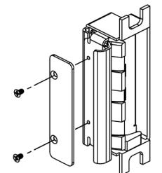
- 10. Insert electric strike in jamb cutout and install the appropriate faceplate using the #12-24 screws provided. Partially tighten screws and close the door.
- 11. Verify lockset's deadlatch is positioned on top of the deadlatch platform, and does not touch the faceplate. See troubleshooting tips for more information.
Set Horizontal Adjustment
- 12. Open the door and pull the electric strike flush with the inside face of the frame (in the direction of the opening), and tighten screws.
- 13. Close the door. If excessive movement (door play) when latched, remove strike from the jamb cutout, and add one or two of the horizontal lockdown shims to the front face of the electric strike (See Diagram 6 on page 6). Ensure the horizontal lockdown shim is making contact with the inside face of the frame. Check again and add or remove additional shims until proper horizontal adjustment is achieved.
Note: The gap between the door and the frame at the strike plate varies. Verify latchbolt guarding with door closed.
DIAGRAM 1: 12V to 24V CONVERSION
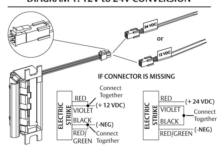
DIAGRAM 2: LBM & LBSM WIRING
LBM WIRING White Common Orange Normally Open Green Normally Closed LBSM WIRING Brown Common Blue Normally Open
Normally Closed
Yellow
Important Trouble Shooting Tips
NOTE: In order to ensure proper catch and release of the latchbolt, the 8500 electric strike requires that the opening be plumb and square .
Door sag and latchbolt wear are two common conditions that may prevent an electric strike from working properly. Here are some quick tips to ensure the HES 8500 performs at its best:
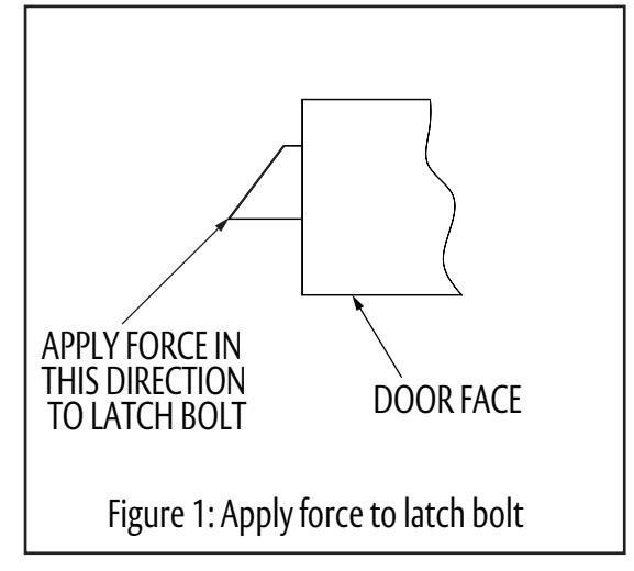
EVALUATING LATCH BOLT CONDITION
Poorly constructed, worn or damaged latchbolts may not interact properly with the ramp of an electric strike. Check the condition of your latchbolt by lightly pressing the tip of the latchbolt at a 45 degree angle to the door face. (See Figure 1). The latchbolt should be pushed easily into the door.
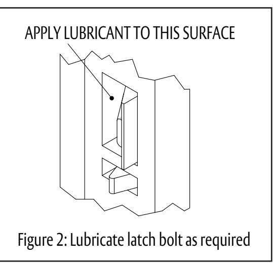
If abnormal resistance is encountered, apply a lubricant to the inside of the latchbolt opening while pressing the latchbolt . (See Figure 2). If this does not correct the friction, additional maintenance on the latchbolt may be required. Note: Check with the latchbolt manufacturer regarding proper latchbolt maintenance and approved lubricants.
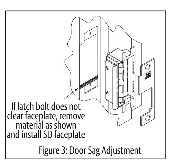
ACCOMMODATING DOOR SAG
Most doors experience some sagging over time. To check for door sag, look at the location of the lock's deadlatch in relation to the 8500's deadlatch platform. The deadlatch should rest on the deadlatch platform. If the deadlatch contacts the faceplate or the edge of the 8500's body, the latchbolt may not be fully released when the strike is activated causing the door not to be released.
To correct this condition, remove the 8500 and cut material from the bottom edge of the frame opening and possibly the mounting tabs (Note: make sure to sure to retain the mounting hole). This allows the 8500 to be shifted down slightly in the frame. Reinstall the 8500, using the SD faceplate instead of the standard faceplate.
If this does not correct the issue, additional maintenance on the door may be necessary.
STRIKE LUBRICATION
Lubrication of the 8500 electric strike is not necessary.
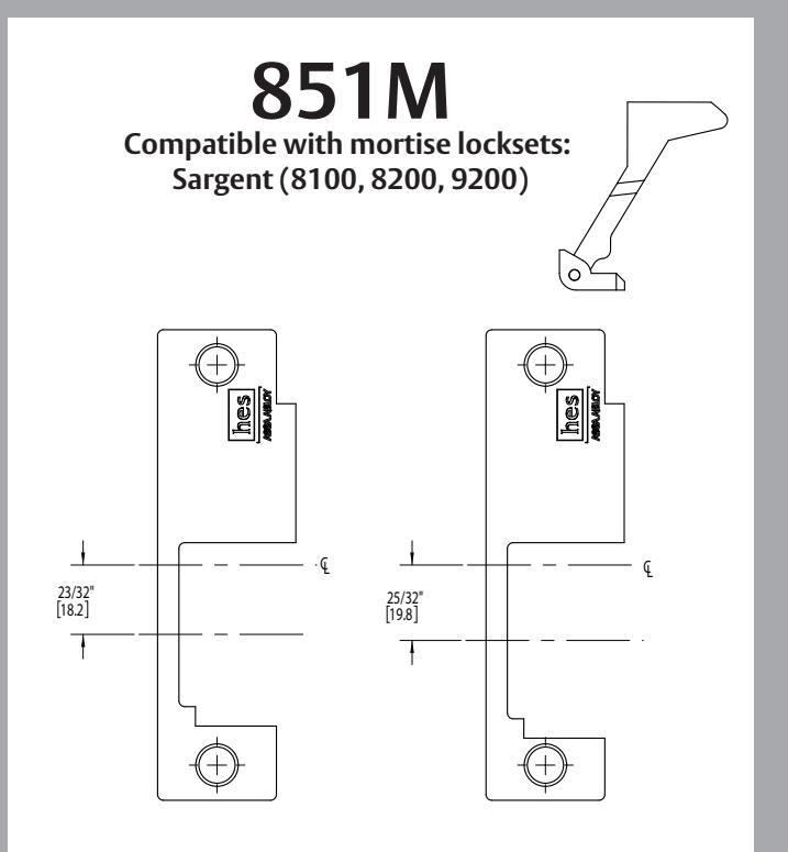
8500 Options
CL = centerline of faceplate 2nd line = centerline of faceplate opening
Installation Diagrams
DIAGRAM 3: Fail Safe Conversion
- a Remove and discard the fire screw (Located under the UL fire label).
- b Loosen screws, but do not remove them.
- Move screws to the Fail Safe position as shown.
- d Tighten screws.
- Discard the UL label that's located over the screw, as well as the UL label located inside the strike pocket.
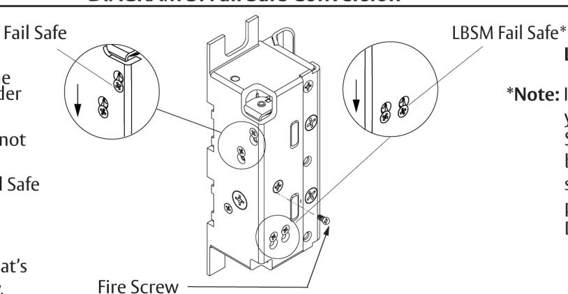
LBSM
*Note: If you are using LBSM and you want to convert to Fail Safe mode, follow steps a, b, and c. Then move the switch to the Fail Safe position, as shown in Diagram 3.
DIAGRAM 4: Deadlatch Platform Position
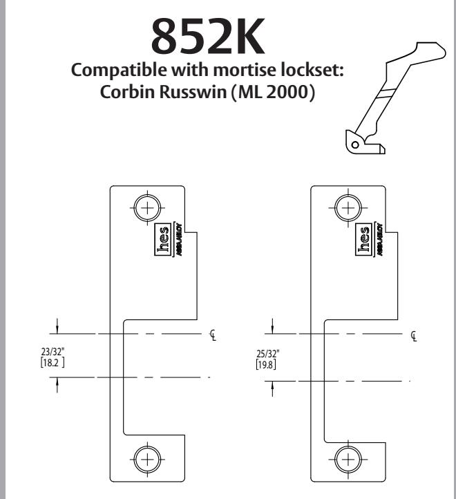
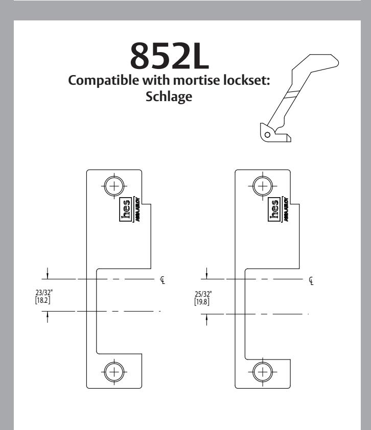
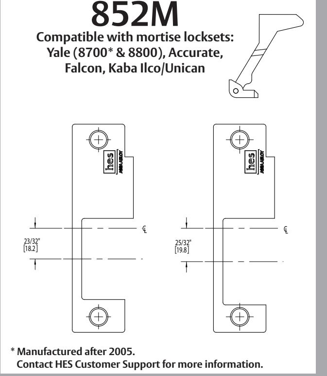
| Sargent 8100, 8200, 9200 Yale 8800 Accurate Falcon Kaba Ilco/Unican Corbin Russwin ML 2000 Schlage L9000 | Lockset |
Platform
Style |
Platform Position 1 | Lockset |
Platform
Style |
Platform Position 2 |
|---|---|---|---|---|---|---|
| LH/RHR handed position shown |
2200
Yale 8800 Accurate Yalcon Yaba Ilco/Unican Yorbin Russwin |
K | Schlage L9000 | L |
* Manufactured after 2005. Contact HES Customer Support for more information
DIAGRAM 5: Deadlatch Platform Installation
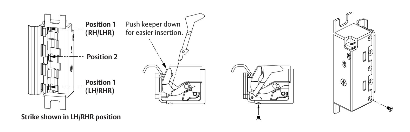
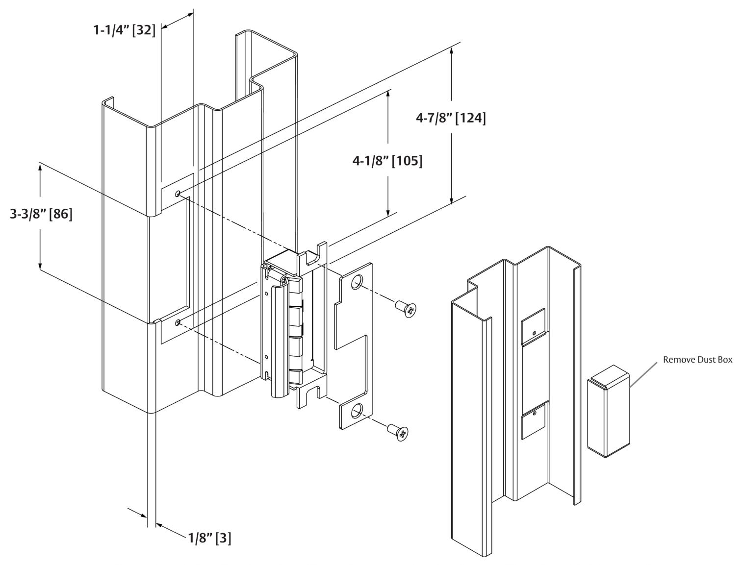
*Note: The 8500 electric strike will require removal of dust boxes of less than 1-3/8" in depth. Remove additional material as needed to provide clearance for electric strike and wires.
DIAGRAM 6: Horizontal Lockdown Shim Installation
1 Shim = 1/16" [1.6] 2 Shims = 1/8" [3.2]
3070006.001 rev C © 2011 HES, Inc.