HES 8000 Series Electric Strike Installation Instructions and Troubleshooting Guide
Open the original PDF document
View PDF

Installation Instructions 8000/8300 Series Electric Strike
HES, Inc. Phoenix, AZ 800-626-7590 www.hesinnovations.com
1
Product Components
- 1 8000/8300 Electric Strike Body
- ② Sticky Shims (optional use)
- 3 12 & 24 Volt Pigtails
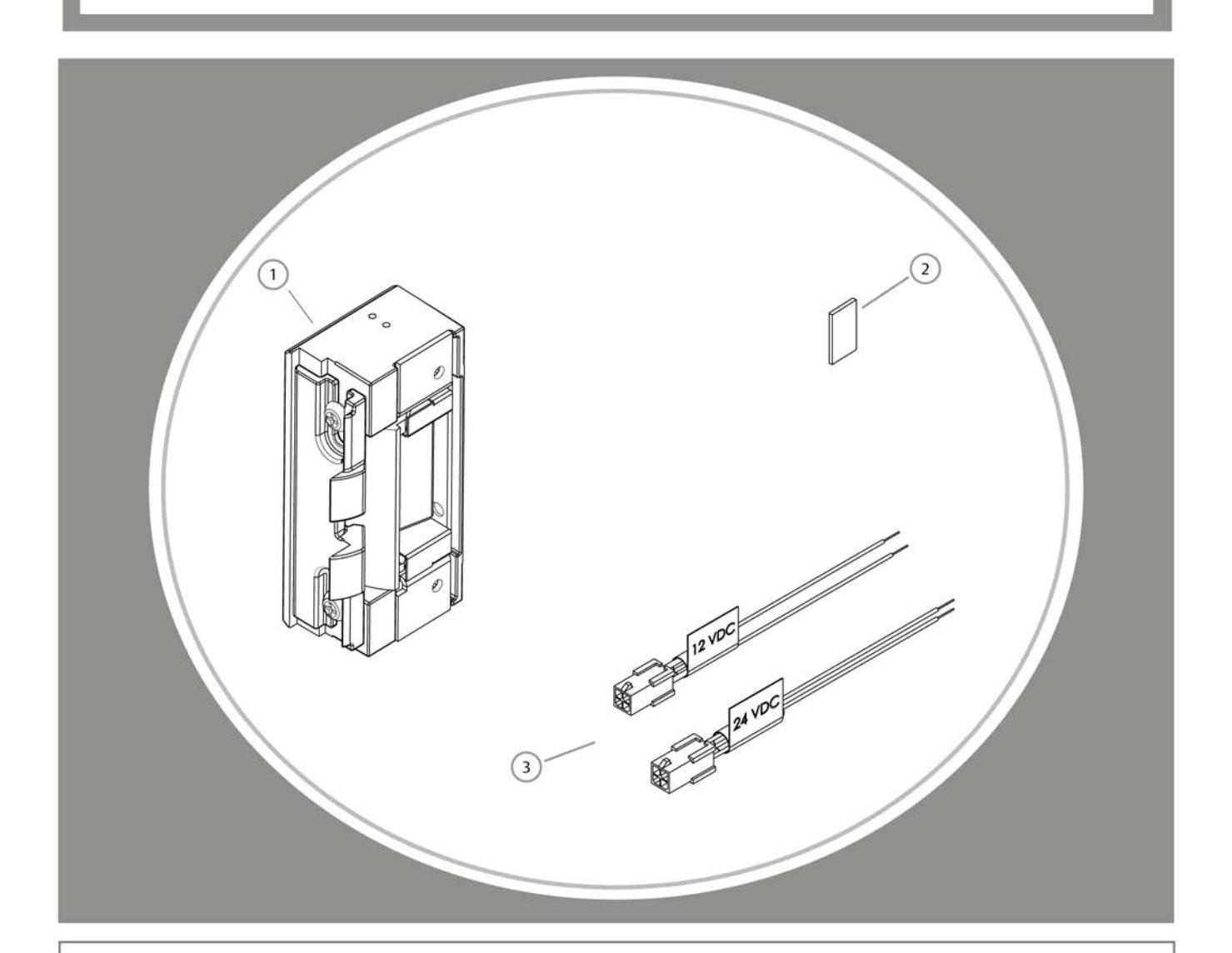
Diagram 1: Electrical Specifications
| ELECTRICAL RATINGS FOR SOLENOID | CONTINUOUS DUTY | INTERMITTENT DUTY* | ||
|---|---|---|---|---|
| 12VDC | 24VDC | 12-16VAC | 24VAC | |
| Resistance in Ohms | 50 | 200 | 50 | 200 |
| Amps | .24 | .12 | .2432 | .12 |
| MINIMUM WIRE GAUGE REQUIREMENTS | SOLENOID VOLTAGE | ||
|---|---|---|---|
| 12VDC | 24VDC | ||
| 200 feet or less | 18 gauge | 20 gauge | |
| 200 - 300 feet | 16 gauge | 18 gauge | |
| 300 - 400 feet | 14 gauge | 16 gauge | |
Installation Directions
CAUTION! Before connecting any device at the installation site, verify input voltage using a multimeter. Many power supplies and low voltage transformers operate at higher levels than listed. Any input voltage exceeding 10% of the solenoid rating may cause severe damage to the unit and will void the warranty.
Evaluate Opening
1. Verify opening is plumb and square. For important detail, see pages 4-5.
Prepare Strike
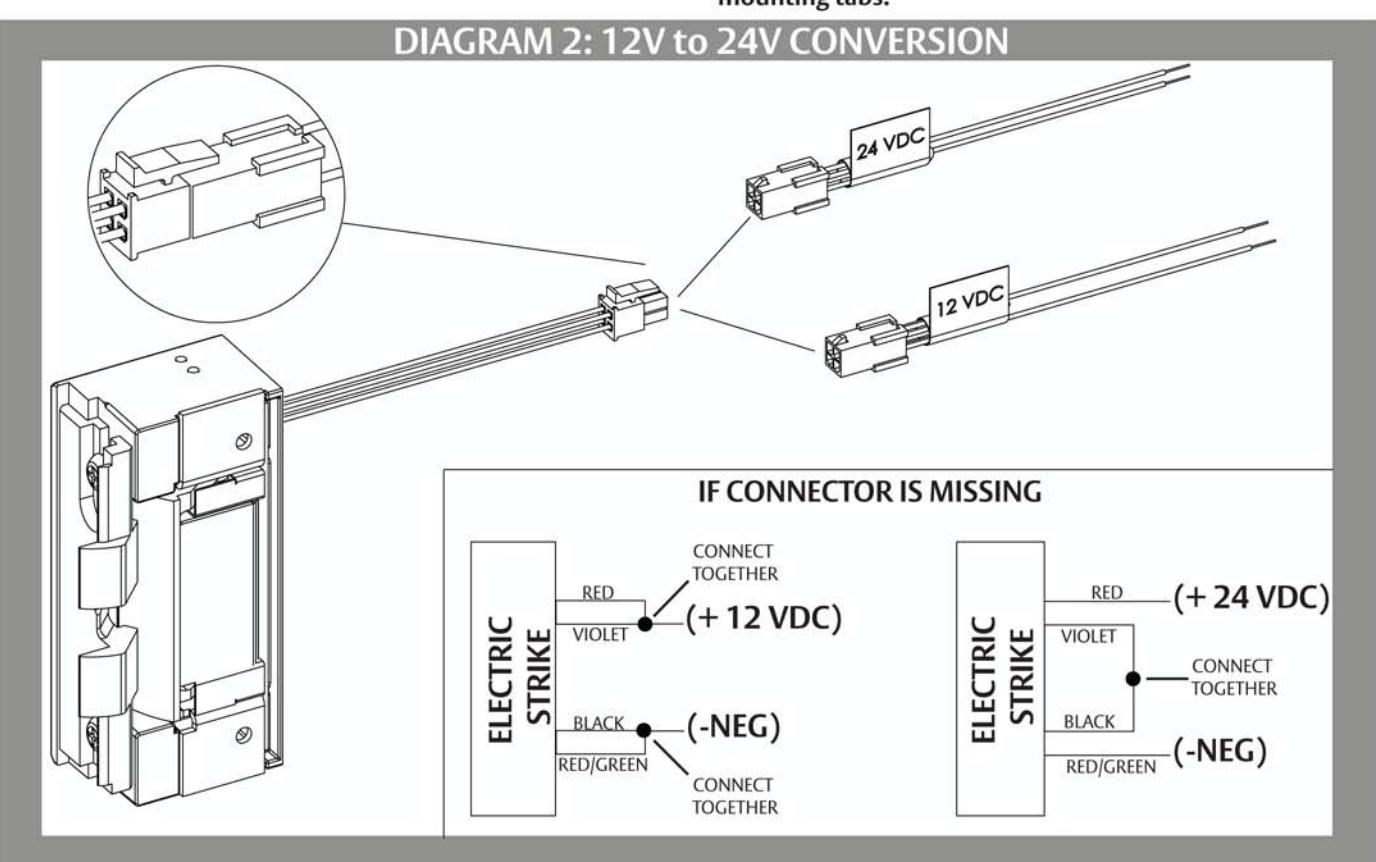
- 2. Select the appropriate Plug In Connector that matches system power and electrically connect as illustrated in Diagram 2. For 12V AC/DC or 16V AC, the pigtail marked "12 VDC" should be used. For 24V AC/DC, the pigtail marked "24 VDC" should be used. If no connector is present, configure the wires as illustrated within Diagram 2.
- 3. Make sure that the electric strike is in correct mode of operation. This electric strike ships in fail secure mode. If you need to convert the unit to fail safe, see Diagram 3 on page 3.
- 4. If using Latchbolt Monitor (LBM), see Diagram 4.
- 5. Attach the faceplate to the electric strike, using the #8-32 screws provided. Be sure that the ramps are on top of the faceplate. (see Diagram 5 on page 3).
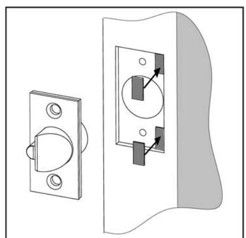
Prepare Frame
6. Prepare door jamb per the appropriate template detail (see pages 6-8).
7. If applicable, install mounting tabs using #10-32 screws. Do not tighten.
Finish Installing
- 8. If opening is not plumb and square, see pages 4-5 for recommended corrections.
- 9. Install the electric strike unit in jamb cutout, using #12-24 screws provided (or wood screws where necessary).
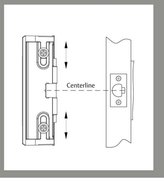
- 10. The deadlatch must not interfere with the 8000/8300 ramps (see Diagram 6 on page 3). If you need to adjust the ramps, mark the centerline of the deadlatch onto the 8000/8300 faceplate. Remove the 8000/8300 electric strike from jamb. Loosen screws and slide internal ramp until the groove between the ramps aligns with the mark made on the faceplate. Tighten the screws. (see Diagram 7 on page 3).
- 11. Connect wires from power source to the electric strike.
- 12. Reinstall electric strike, tighten the #12-24 screws and verify clearance of deadlatch.
- 13. If applicable, tighten the #10-32 screws holding the mounting tabs.

- a Loosen screws, but do not remove them
- b Move screws to the Fail Safe position as shown
- (c) Tighten screws

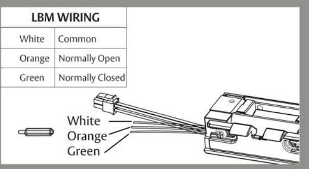
DIAGRAM 5: FACEPLATE INSTALLATION
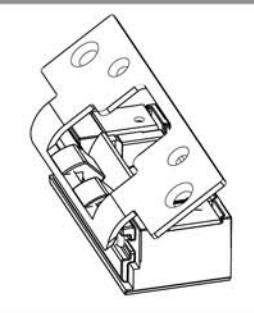
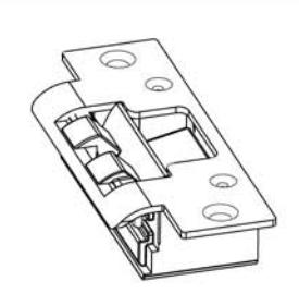
DIAGRAM 6: VERTICAL ALIGNMENT
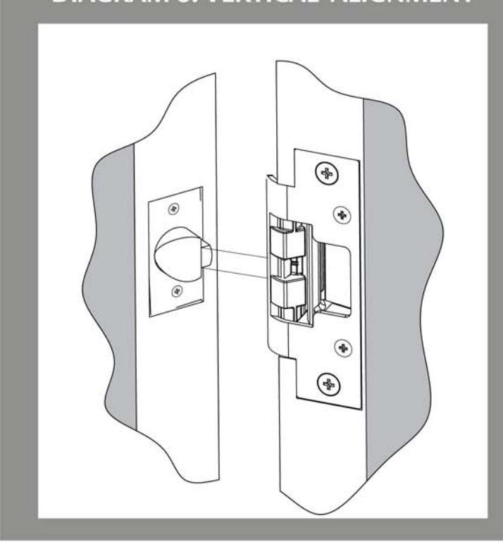
DIAGRAM 7: VERTICAL ADJUSTABILITY
A NEW KIND OF ELECTRIC STRIKE
A standard electric strike requires a cutout on the side of the door frame to allow the extended latchbolt to exit the frame. In contrast, the 8000/8300 is designed to utilize special internal ramps to eject the latchbolt from an unmodified frame. For the 8000/8300 to operate correctly, it is important for you to first understand the relationship between the unit's internal ramps and the position of the latchbolt.
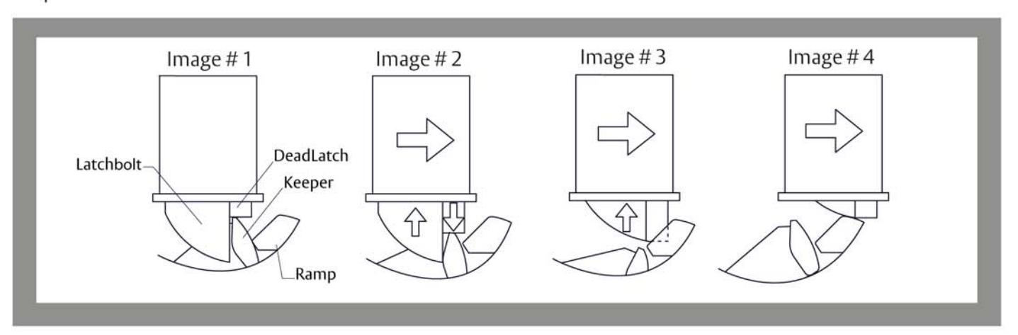
- 1. Initially, the 8000/8300 operates very much like a standard electric strike. With the door in the closed position, the latchbolt held secure by the 8000/8300's keeper (Image 1).
- 2. When energized, the keeper releases the latchbolt and as the door moves forward the deadlatch begins to drop (Image 2).
- 3. As the door continues to move forward the deadlatch and latchbolt will become fully released. The latchbolt will then pass from the keeper and begin to slide up the internal ramps (Image 3). Note: It is important that the deadlatch pass between the two internal ramps without contacting either ramp. The ramp adjustment is explained in detail within installation instructions.
- 4. As the door continues to open, the latchbolt and deadlatch will continue to slide up the internal ramps and out of the door frame to release the door. (Image 4)
WHY ANGLES ARE IMPORTANT
The 8000/8300 ramps are designed with critical angles that minimize both latchbolt wear and the force required for exit. For optimum performance, the latchbolt should be positioned at a 40 to 45 degree angle in relation to the ramps of the 8000/8300. An angle more than 45 degrees will steepen the ramp and impact the performance of the 8000/8300 (Image 5).
We understand that correctly measuring this angle in the field may be difficult. The next section is designed to help you understand some simple techniques to evaluate the condition and relationships between the door, the latchbolt, the frame and the 8000/8300.
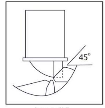
Image #5
Trouble Shooting Tips
NOTE! The 8000/8300 electric strike requires that the opening be plumb and square to insure proper catch and release of the latchbolt.
EVALUATE OPENING
Although the design of the 8000/8300 provides adjustability to compensate for frame and door irregularities, in some cases, adjust ing the frame and door back to industry standards is just not an option. Here are some tips to quickly compensate for frame twist and to determine the condition of the latch bolt.
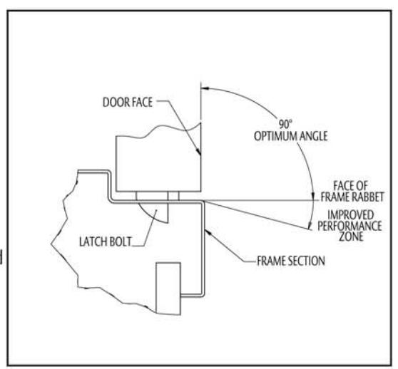
One way to measure frame twist is to place a carpenter square on the stop and the face of the door. If the angle is less than 90 degrees, the 45 degree ramp angle of the 8000/8300 is steepened and may need to be corrected as shown at right.
We also recommend you check the condition of the latch bolt prior to installing the 8000/8300. Poorly constructed, worn out or damaged latch bolts may not slide along a ramp at any angle. To check the condition of your latch bolt, we recommend applying a slight force to the tip of the latch bolt (about 45 degrees to door face). Make sure the latch bolt can be pushed up into the door.

When a frame is twisted, the relationship between the face of a closed door and of the inside face of the frame (i.e. Rabbet) may not meet the 90 degree industry standard. Untrue frames and doors impact latch bolt wear and the force required to exit, so we recommend you ensure that the angle is between degrees.
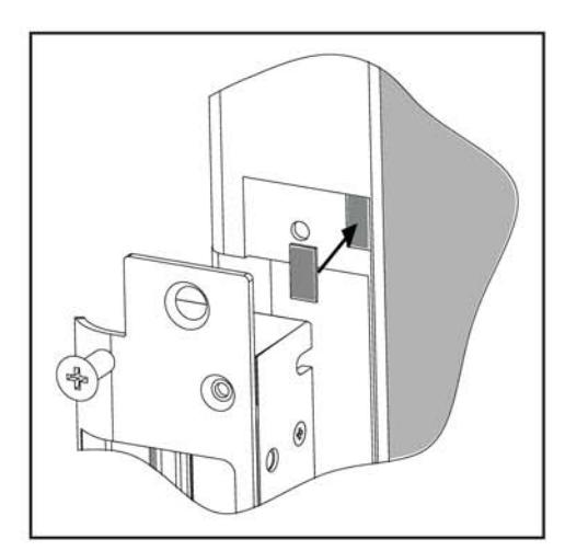
If manipulating the frame is not possible, we recommend placing several shims under the top and bottom (stop side) of the faceplate (Image right). This effectively increases the 8000/8300 ramp angle and compensates for frame twist. This can also be performed by placing shims under the top and bottom (bevel side) of the latchbolt (Image below right).
Inches [mm]
8000/8300 with 801 Faceplate
1-1/4" X 4-7/8" Square Corner Faceplate ANSI Metal Jamb Installations
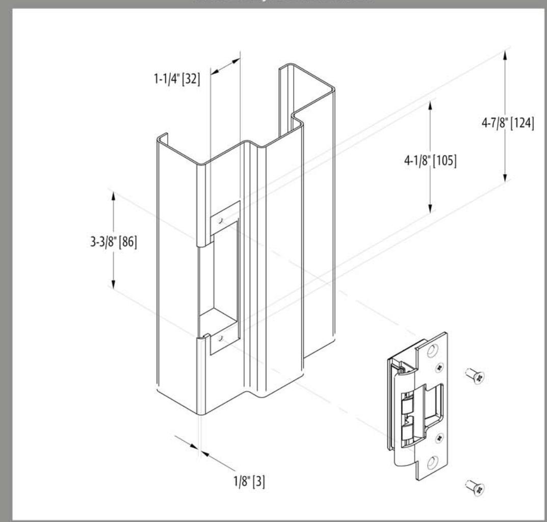
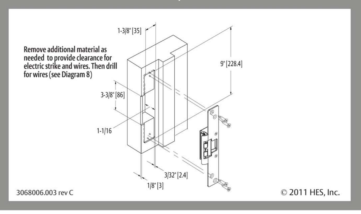
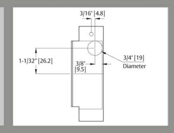
DIAGRAM 8: WIRE DRILLING
NOTE: The 8000/8300 electric strike with 801faceplate will fit right into most standard ANSI A115.2, 1" deep dustboxes (e.g. the Curries® E-1 preparation), requiring no cutting.
If you elect to place the 8000/8300 into the existing dustbox, simply drill for wire connections.
Inches [mm]
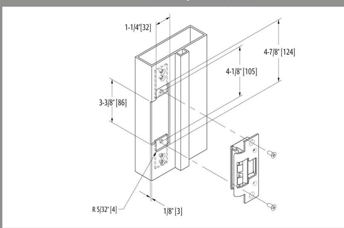
8000/8300 with 801A Faceplate
1-1/4" x 4-7/8" Radius Corner Faceplate Aluminum Jamb Installations
8000/8300 with 802 Faceplate
1-7/16" x 7-15/16" Radius Corner Faceplate Aluminum and Wood Jamb Installations
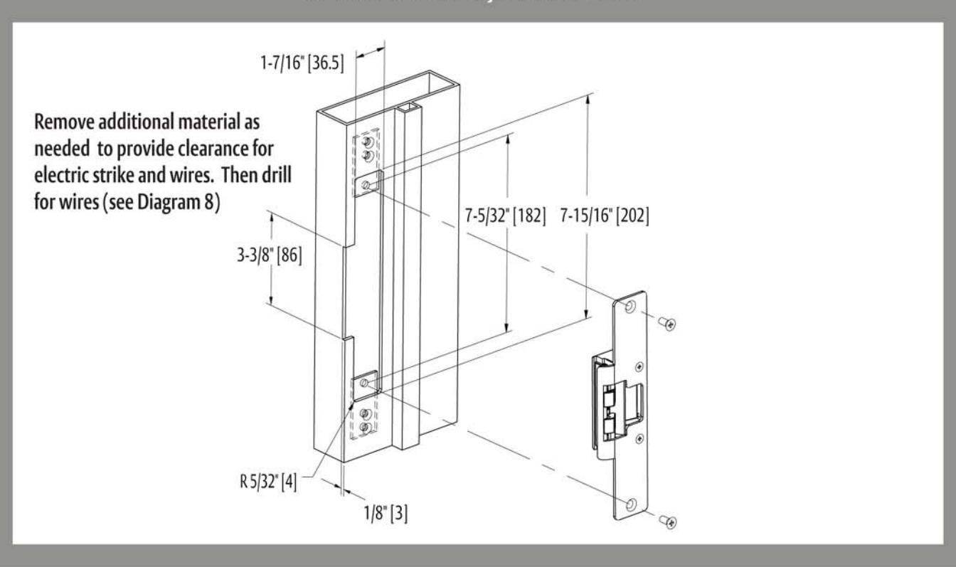
Inches [mm]
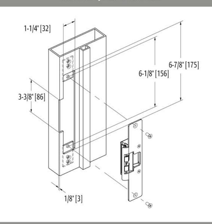
8000/8300 with 803 Faceplate
1-1/4" x 6-7/8" Radius Corner Faceplate Aluminum Jamb Installations
8000/8300 with 805 Faceplate
1-3/8" x 9" Radius Corner Faceplate Aluminum or Wood Jamb Installations