HES 7501 Series Electric Strike Installation Instructions
Open the original PDF document
View PDF

HES, Inc. Phoenix, AZ 800-626-7590 www.hesinnovations.com
3025006.001 rev 3
Copyright © 2017, Hanchett Entry Systems, Inc., an ASSA ABLOY Group company. All rights reserved. Reproduction in whole or in part without the express written permission of Hanchett Entry Systems, Inc. is prohibited.

7501 Electric Strike Installation Instructions
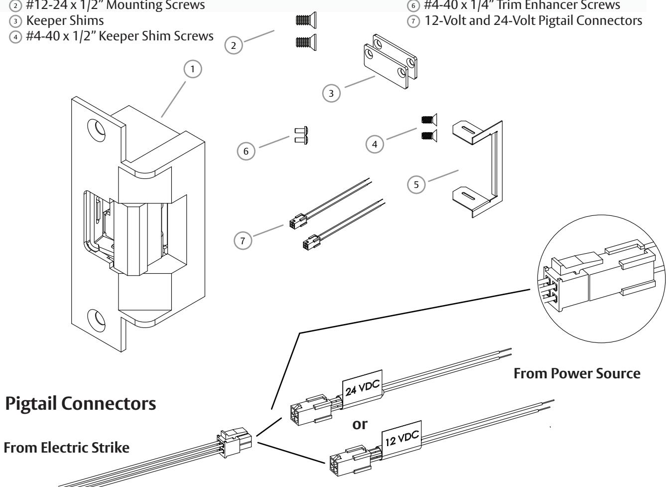
Components
- 7501 Electric Strike Body #12-24 x 1/2" Mounting Screws

6 #4-40 x 1/4" Trim Enhancer Screws
1
Specifications
|
ELECTRICAL RATINGS
(Solenoid) |
Solenoids are rated at +/- 10% indicated value. * Applies to AC Only: 10% max duty cycle (2 min. max on time) | |||
|---|---|---|---|---|
| VOLTAGE | 12 VDC | 24 VDC | 12–16 VAC | 24 VAC |
| CONTINUOUS DUTY | 0.24A | 0.12A | - | - |
| INTERMITTENT DUTY* | - | - | 0.24-0.32A | 0.12A |
| VOLTAGE | ||||
|---|---|---|---|---|
| MINIMUM WIRE GAUGE REQUIREMENTS | 12 VDC | 24 VDC | ||
| 200 feet or less | 18 gauge | 20 gauge | ||
| 200 - 300 feet | 16 gauge | 18 gauge | ||
| 300 - 400 feet | 14 gauge | 16 gauge | ||
Ratings
Static Strength: 1,500 lbs Dynamic Impact: 70 ft-lbs Endurance: 500,000 cycles
ASSA ABLOY, the global leader in door opening solutions
UL294 Performance Levels
Destructive Attack: Line Security: Endurance: Standby Power:
Level 1 (No attack test) Level I (No Line Security) Level IV (100,000 cycles)
Level I (No secondary power source)
Installation 2 3
NOTE 1: Before electrically connecting the device, the input voltage must be verified using a multimeter. Many power supplies and low voltage transformers operate at higher levels than listed. Any input voltage exceeding 10% of the electrical specification (See Page 1) may cause severe damage to the unit and will void the warranty.
NOTE 2: Installation wiring for the product and wiring methods shall be in accordance with the National Electrical Code, ANSI/NFPA 70.
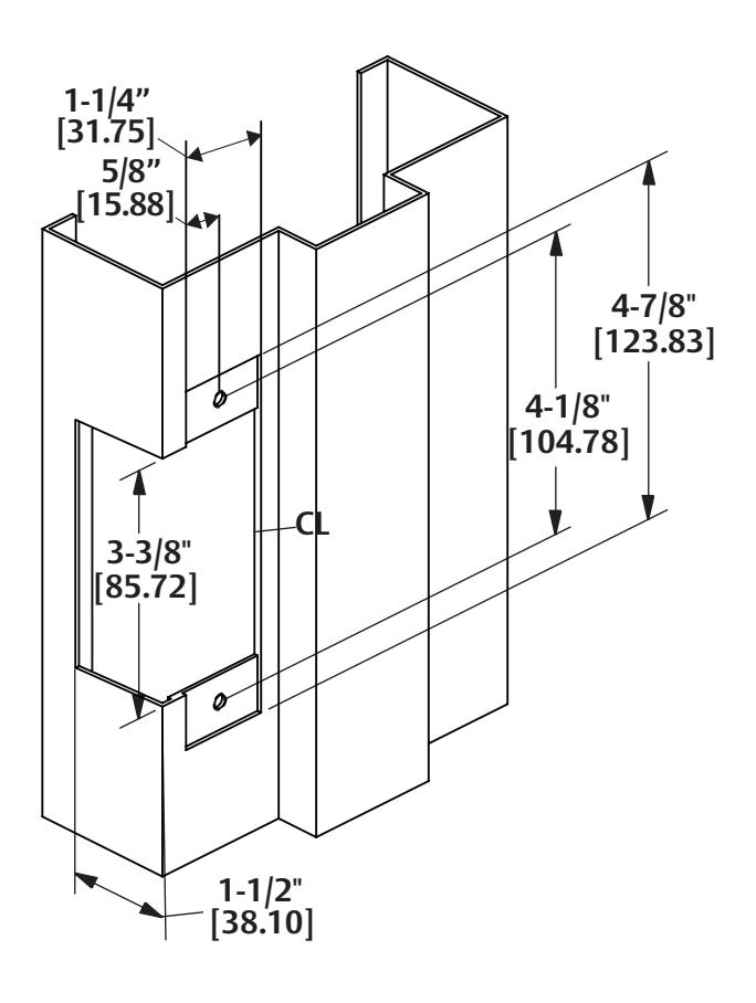
Preparing the Frame
- 1. PREPARE door jamb per the appropriate template detail on Page 3.
- 2. IF using the Latchbolt Monitor (LBM), THEN SEE "LBM Wiring" on Page 2.
Installation
NOTE: For 12 VDC, the Plug In Connector (pigtail) marked "12 VDC" should be used; for 24 VDC, the pigtail marked "24 VDC" should be used.
- 1. CONNECT pigtail connector to the electric strike and to power source (See Page 1).
- 2. IF Operation Mode must be changed,
- GOTO and PERFORM steps in "Converting the Operation Mode" section.
- 3. INSTALL the electric strike in the jamb cutout using the #12-24 x 1/2" mounting screws.
- 4. INSTALL keeper shims as shown on Page 3, if necessary.
- 5. INSTALL the trim enhancer as shown on Page 3, if necessary.
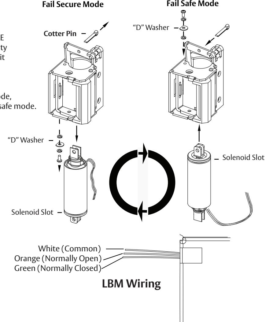
Converting the Operation Mode
NOTE: The suitability of the locks in the FAIL SECURE OPERATION mode is up to the local Authority Having Jurisdiction (AHJ) and emergency exit hardware may be required in such installations.
- 1. Because the electric strike ships in fail secure mode, COMPLETE the following steps to convert to fail safe mode.
- 2. REMOVE the cotter pin from the solenoid linkage.
- 3. REMOVE the solenoid mounting screw and washers.
- 4. REMOVE the solenoid from the keeper module.
- 5. TURN the solenoid upside down, and RE-INSERT it into the keeper module.
- 6. RE-INSTALL the mounting screw and washers at the opposite end of the keeper module, and ENSURE the "D" washer is positioned firmly into the solenoid slot.
- 7. REPLACE the cotter pin to secure the solenoid linkage.
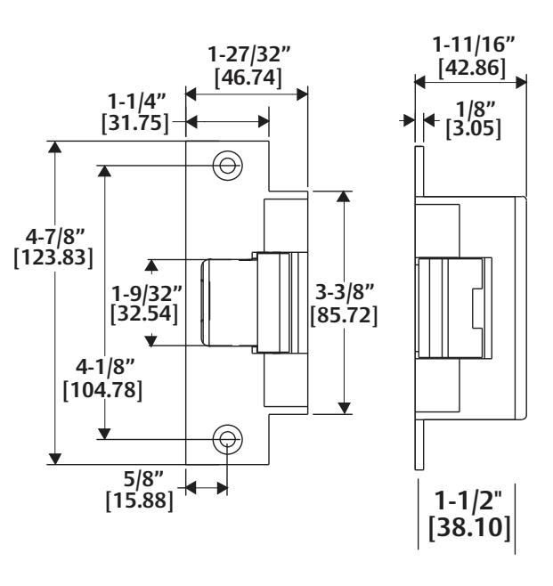
7501 Template & Dimensions
Installing the Keeper Shims
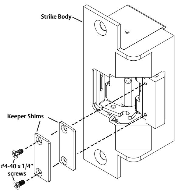
UNLOCK the electric strike, ALIGN the keeper shims as shown, and FASTEN to the keeper using the provided #4-40 x 1/4" screws.
Installing the Trim Enhancer
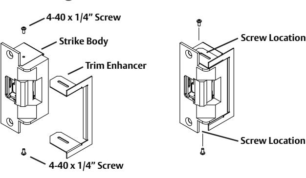
LINE UP Trim Enhancer with strike body as illustrated above.
FASTEN the Trim Enhancer to the strike at the screw location illustrated above.
NOTE: It may be necessary to enlarge the cutout to accommodate the added thickness of the Trim Enhancer & screws.