HES 7000 Series Electric Strike Installation Instructions
Open the original PDF document
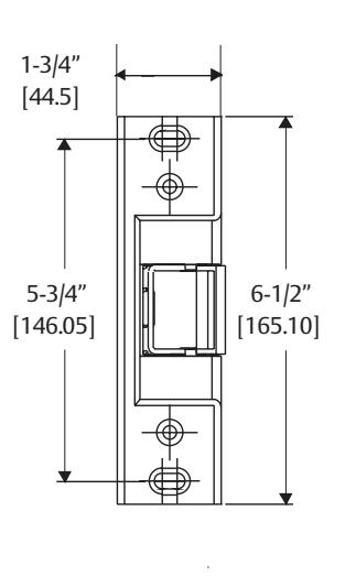
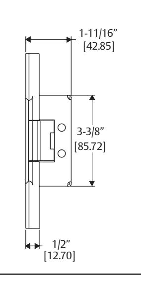
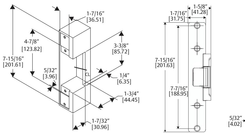
View PDFCutout Templates (continued)
NOTE 1: For use with RIM exit devices in metal jambs with up to a 3/4" pullman latch.
NOTE 2: Compatible with American Device, Arrow, Dor-O-Matic, Monarch, Precision, Sargent. Von Duprin, and Yale.
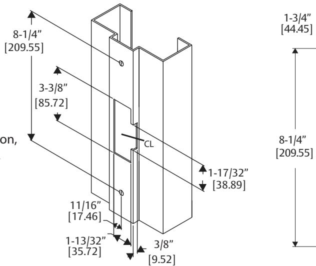
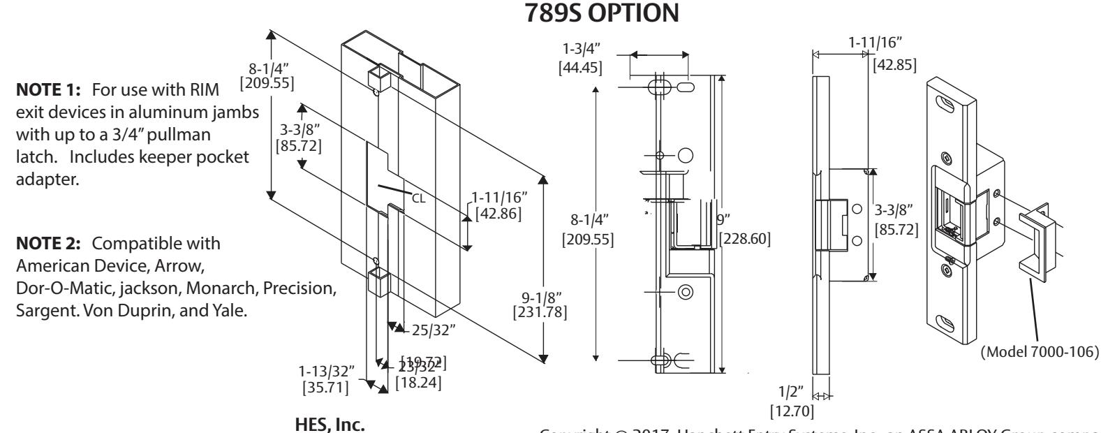
783S OPTION
786S OPTION
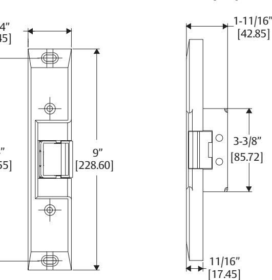
Inches [mm]
NOTE 1: For use with RIM exit devices in aluminum jambs and surface mounted vertical rod exit devices with up to a 3/4" pullman latch. Includes [146.05] 3-3/8" keeper socket adapter. [85.72] NOTE 2: Compatible with American Device, Arrow, <del>^</del>1-17/32" Dor-O-Matic, Jackson, Monarch, [38.89] Precision, Sargent, Von Duprin, and Yale. 11/16" [17.46] 1-13/32" [35.72]
Phoenix, AZ 85044
www.hesinnovations.com
800-626-7590
3021006.002, Revision 3
Copyright © 2017, Hanchett Entry Systems, Inc., an ASSA ABLOY Group company.
All rights reserved. Reproduction in whole or in part without the express written
permission of Hanchett Entry Systems, Inc. is prohibited.
hes
7000 Series Electric Strike
Installation Instructions
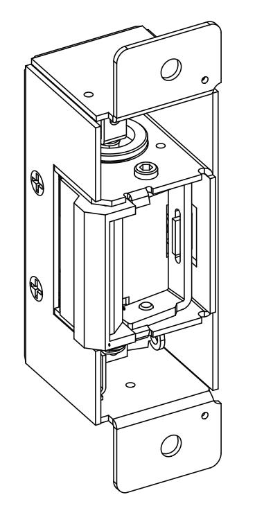
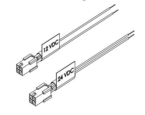
Product Components
7000 Series Electric Strike Body
12-Volt and 24-Volt Pigtail Connectors
Specifications
|
ELECTRICAL RATINGS
(Solenoid) |
Solenoids are rated at +/- 10% indicated value. * Applies to AC Only: 10% max duty cycle (2 min. max on time) | |||
|---|---|---|---|---|
| VOLTAGE | 12 VDC | 24 VDC | 12–16 VAC | 24 VAC |
| CONTINUOUS DUTY | 0.24A | 0.12A | - | - |
| INTERMITTENT DUTY* | - | - | 0.24-0.32A | 0.12A |
| VOLTAGE | |||
|---|---|---|---|
| MINIMUM WIRE GAUGE REQUIREMENTS | 12 VDC | 24 VDC | |
| 200 feet or less | 18 gauge | 20 gauge | |
| 200 - 300 feet | 16 gauge | 18 gauge | |
| 300 - 400 feet | 14 gauge | 16 gauge | |
7000 Series: For Indoor Use Only
Ratings
Endurance:
791/792 783S/786S/789S
Static Strength: Dynamic Impact:
1,500 lbs 70 ft-lbs 500,000 cycles
1000 lbs 50 ft-lbs 500,000 cycles
UL294 Performance Levels
Destructive Attack: Line Security: Endurance: Standby Power:
Level 1 (No attack test) Level I (No Line Security) Level IV (100,000 cycles) Level I (No secondary power source)
ASSA ABLOY, the global leader in door opening solutions
Installation
NOTE 1: Before electrically connecting the device, the input voltage must be verified using a multimeter. Many power supplies and low voltage transformers operate at higher levels than listed. Any input voltage exceeding 10% of the electrical specification (See Page 1) may cause severe damage to the unit and will void the warranty.
NOTE 2: Installation wiring for the product and wiring methods shall be in accordance with the National Electrical Code, ANSI/NFPA 70.
Preparing the Frame
1. PREPARE door jamb per the appropriate template detail (see pages 3–4).
Finishing the Installation
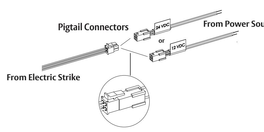
NOTE: For 12 VDC, the Plug In Connector (pigtail) marked "12 VDC" should be used; for 24 VDC, the pigtail marked "24 VDC" should be used.
1. CONNECT power to the electric strike, and INSTALL into jamb using the hardware provided with the option kit.
Converting the Operation Mode
NOTE: The suitability of the locks in the FAIL SECURE OPERATION mode is up to the local Authority Having Jurisdiction (AHJ) and emergency exit "D" Washer hardware may be required in such installations.
1. Because the electric strike ships in fail secure mode, COMPLETE the following steps to convert to fail safe mode.
a. REMOVE the cotter pin from the solenoid linkage.
b. REMOVE the solenoid mounting screw and washers.
- c. REMOVE the solenoid from the keeper module.
- d. TURN the solenoid upside down, and RE-INSERT it into the keeper module.
- e. RE-INSTALL the mounting screw and washers at the opposite end of the keeper module, and ENSURE the "D" washer is positioned firmly into the solenoid slot.
- f. REPLACE the cotter pin to secure the solenoid linkage.
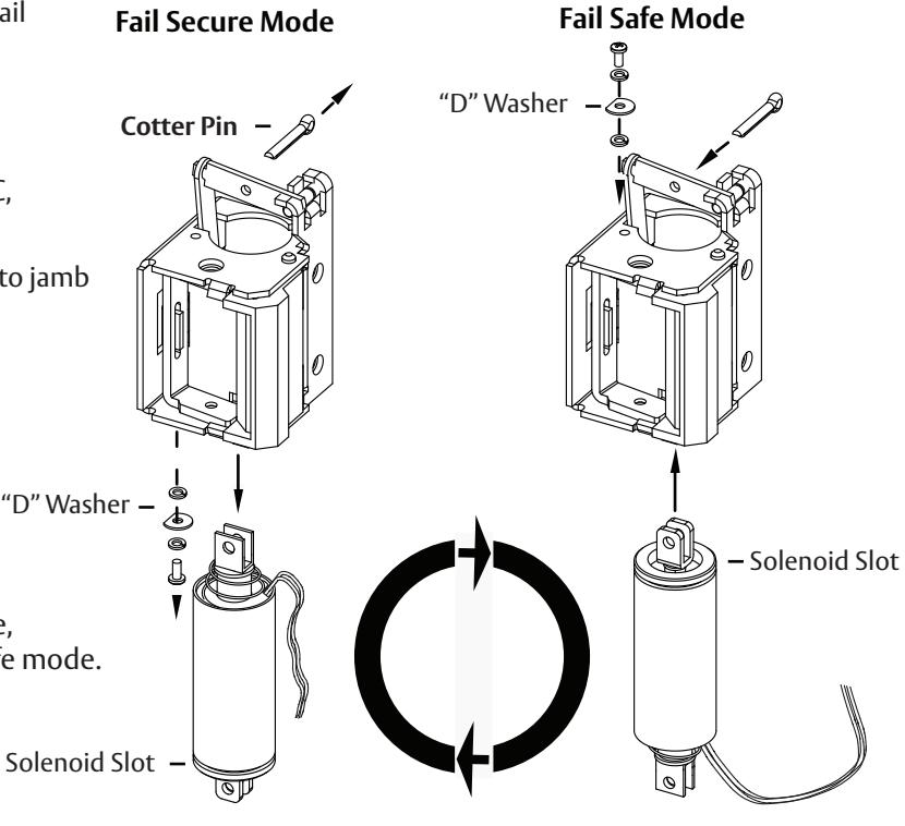
Figure 1. Converting the Operation Mode
Installation (continued)
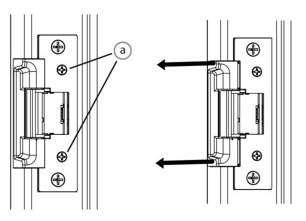
Adjusting the Horizontal in the 791 and 792 Options
- 1. LOOSEN the screws (a), but DO NOT REMOVE.
- 2. SHIFT the electric strike to the proper horizontal position and TIGHTEN the screws (a).
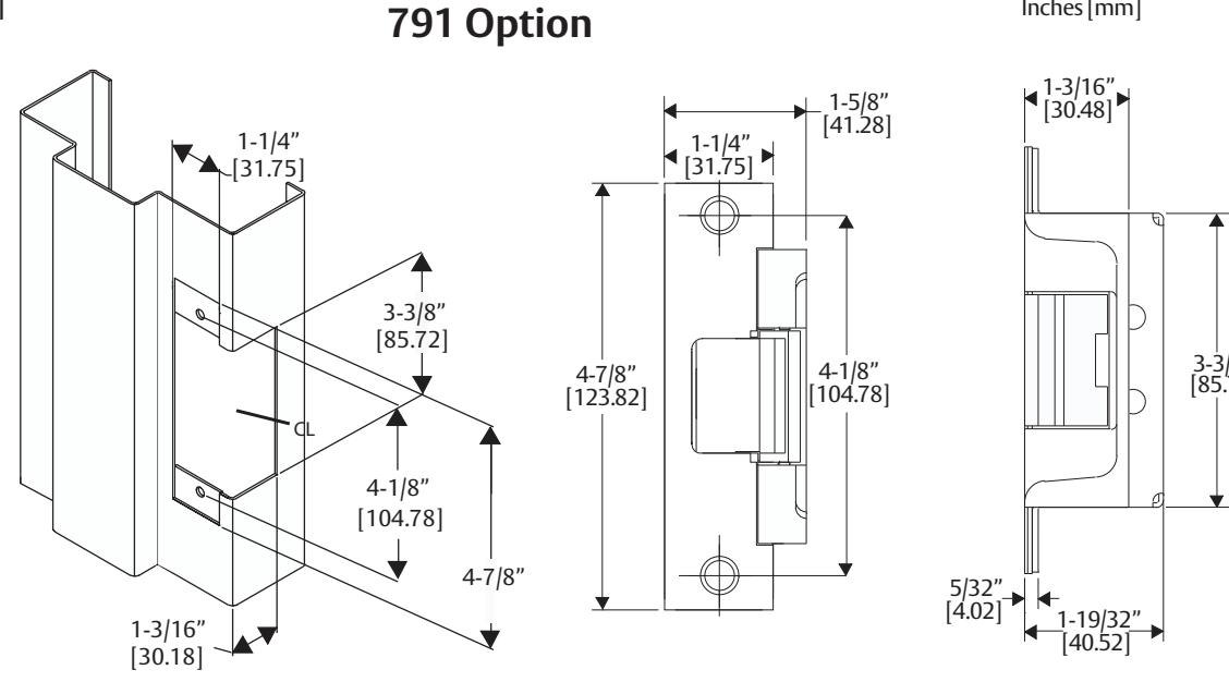
Cutout Templates
NOTE: For use with Cylindrical locksets up to 5/8" throw.
2
NOTE: For use with Cylindrical locksets up to 5/8" throw.
792 Option
Inches [mm]