HES 660 Multi-Purpose Lock Installation Instructions
Open the original PDF document
View PDF

Multi-Purpose Lock Installation Instructions
HES, Inc. Phoenix, AZ 85044 800-626-7590 www.hesinnovations.com
1
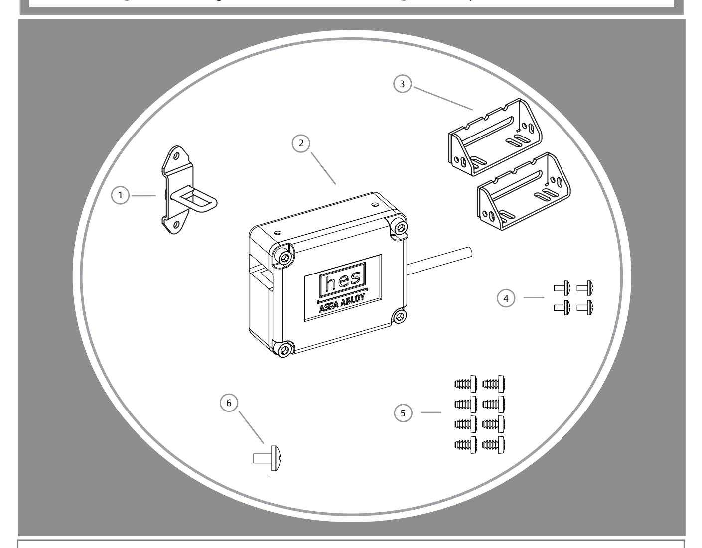
Product Components
- 1 Hook Bracket Assembly
- 2 660 Multi-Purpose Lock Body
- 3 Lock Mounting Brackets
- 4 #6-32 X 3/16" Screws
- 5 #10 X 1/2" Screws
- 6 #8-32 X 5/8" Screw
Electrical Specifications
|
ELECTRICAL RATINGS
FOR SOLENOID |
CONTINUOUS DUTY
STANDARD |
INTERMITTENT DUTY
PRELOAD |
MINIMUM WIRE GAUGE REQUIREMENTS | ||||
|---|---|---|---|---|---|---|---|
| Operating Voltage +/- 10% | 12VDC | 24VDC | 12VDC | 24VDC | SOLENOID VOLTAGE | 12VDC | 24VDC |
| Resistance in Ohms | 48 | 192 | 17 | 67.8 | 200 feet or less | 14 gauge | 18 gauge |
| Watts Seated | 3 | 3 | 8.4 | 8.4 | 200 - 300 feet | 12 gauge | 18 gauge |
| Amps Seated | 250mA | 125mA | 700mA | 350mA | 300 - 400 feet | 12 gauge | 16 gauge |
Installation Directions 2
CAUTION! Before connecting any device at the installation site, verify input voltage using a multimeter. Many power supplies and low voltage transformers operate at higher levels than listed. Any input voltage exceeding 10% of the solenoid rating may cause severe damage to the unit and will void the warranty.
WARNING: The Multi-Purpose Lock Body must be wired to a power source prior to insertion of the Hook Bracket Assembly. Failure to do so may result in a permanently locked cabinet/drawer.
Prepare Lock
- 1. Attach both Lock Mounting Brackets to the Multi-Purpose Lock Body using four #6-32 x 3/16" screws as illustrated in Diagram 1.
- 2. To prevent accidental capture of the Hook Bracket Assembly prior to the Multi-Purpose Lock Body being wired, gently thread the #8-32 X 5/8" screw into the #8-32 threaded hole depicted in Diagram 2. The #8-32 X 5/8" screw must only be tightened snug by hand.
When installed the #8-32 X 5/8" screw will prevent the capture of the Hook Bracket Assembly by the Multi-Purpose Lock Body. When wiring is complete, remove the #8-32 X 5/8" screw. The Multi-Purpose Lock Body will now be able to capture and electrically release the Hook Bracket Assembly.
Prepare Cabinet/Drawer
3. Drill four 1/16" diameter pilot holes in the cabinet using the Mounting Template on page 3, and mount the Multi-Purpose Lock Body to the inside of the cabinet/drawer using four #10 X 1/2" screws.
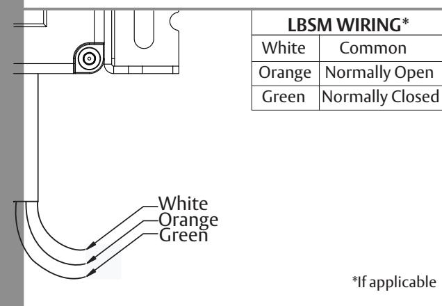
- 4. Refer to Diagram 4 on page 3 to connect power to the Multi-Purpose Lock Body. If your Multi-Purpose Lock is equipped with the RJ-45 option, a diagram for pin assignments is also provided on page 3, Diagram 4. If applicable, the LBSM should also be electrically connected at this time. Remove the #8-32 X 5/8" screw installed in step 2. Verify catch and release of the unmounted Hook Bracket Assembly after power is connected.
- 5. Mark mounting holes for the Hook Bracket Assembly as illustrated on page 4, Diagram 5. Drill two 1/16" X 1/2" deep pilot holes for the Hook Bracket Assembly, and mount the Hook Bracket Assembly using two #10 X 1/2" screws.
Finish Installing
- 6. If lock body adjustment is needed to ensure a smooth capture and release of the hook bracket assembly, loosen the #10 X 1/2" and #6-32 X 3/16" screws to adjust the Multi-Purpose Lock Body until desired clearance is reached.
- 7. If additional stability is desired, drill two 1/16" pilot holes and use two remaining #10 X 1/2" screws for final lockdown of the Multi-Purpose Lock Body as illustrated in Diagram 6, on Page 4.
- 8. If the optional key override is used, prepare the cabinet/drawer as illustrated in Diagram 7, on Page 4.
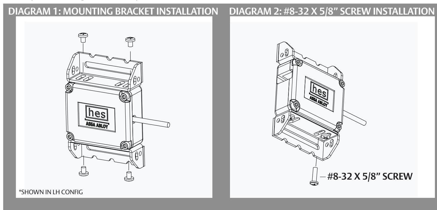
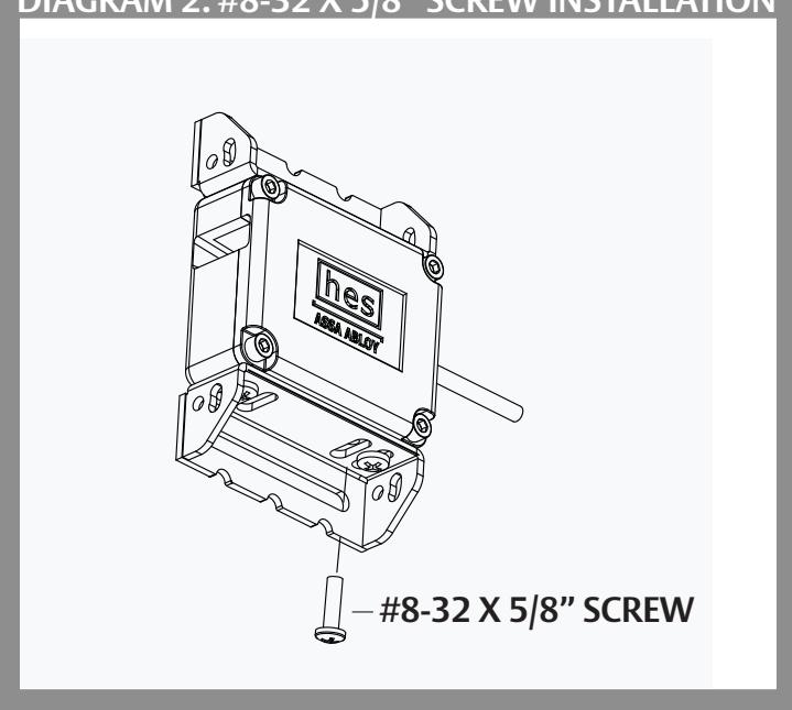
DIAGRAM 3: MOUNTING TEMPLATE
Align dotted line with outer edge of cabinet. Tape Model 660 Mounting Template to inside surface of cabinet.
Drill four 1/16" holes through paper template.
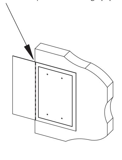

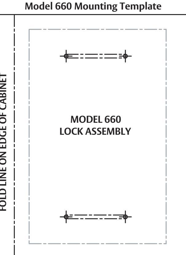
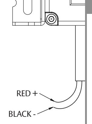
DIAGRAM 4: POWER & LBSM SWITCH WIRING
| POWER WIRING* | ||||
|---|---|---|---|---|
| RED | Positive + | |||
| BLACK | Negative - | |||
*CAUTION! The Multi-Purpose Lock Body is provided as either a 12 or 24 volt unit. Verify the power supply output before operating this device.
RJ-45 OPTION
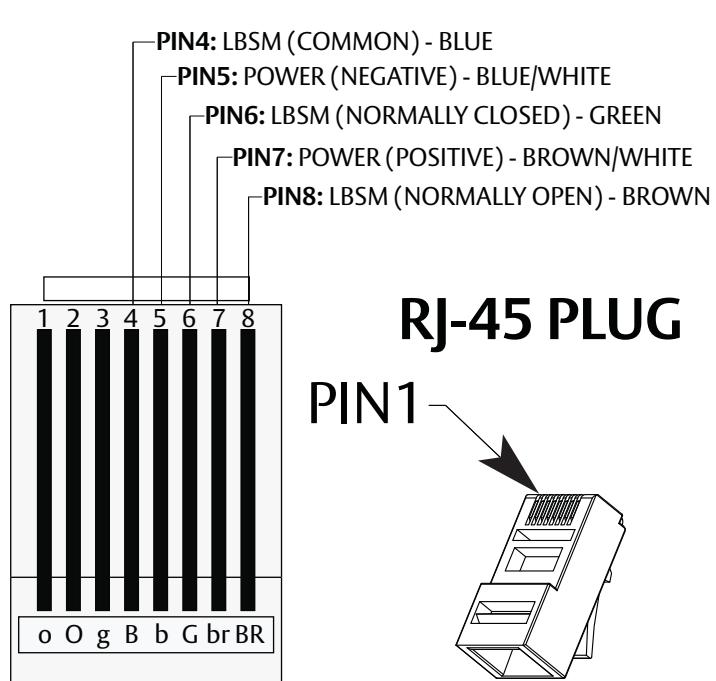
RJ-45 PLUG
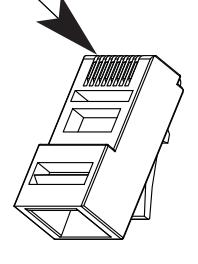
Clip is pointed away from you
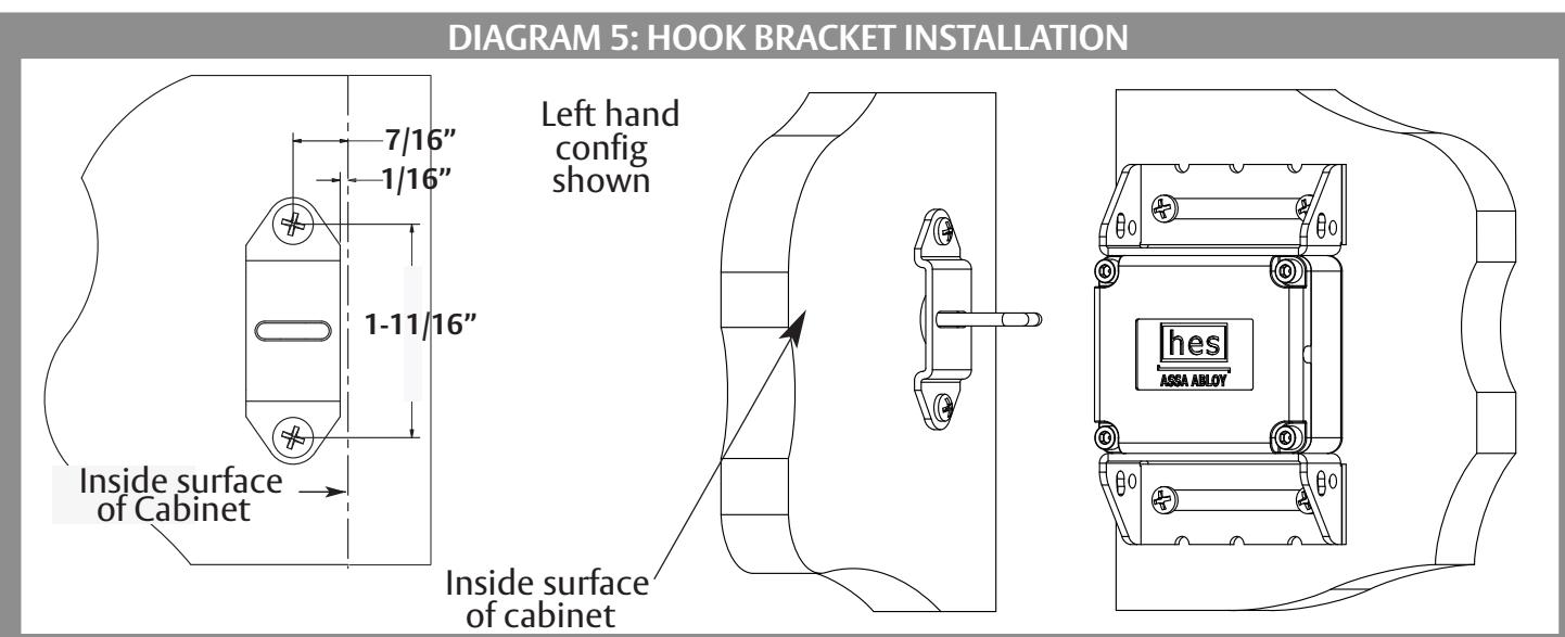
DIAGRAM 6: FINAL LOCKDOWN
DIAGRAM 7: OPTIONAL KEY OVERRIDE
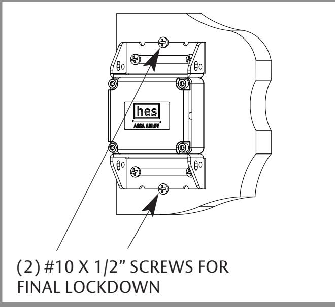
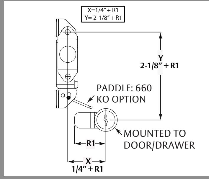
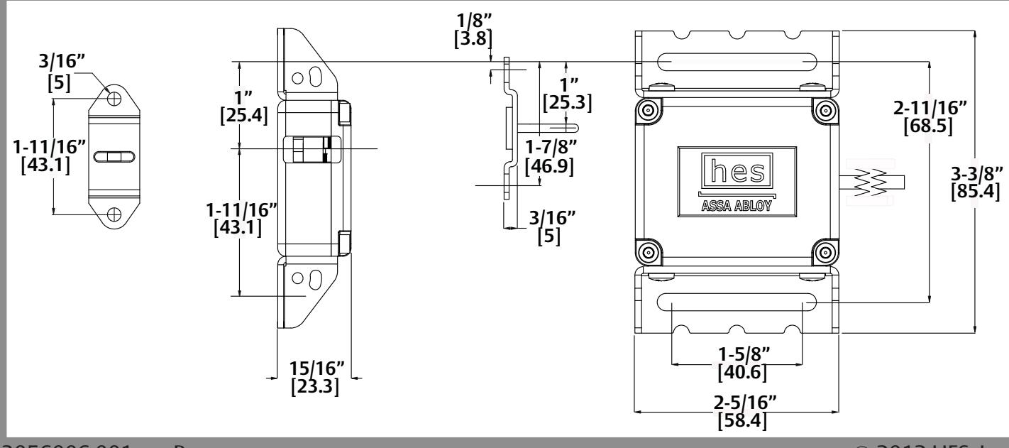
DIAGRAM 8: DIMENSIONS
3056006.001 rev B. © 2012 HES, Inc.