HES 5200 Series Electric Strike Installation Instructions
Open the original PDF document
View PDFCutout Templates for Frame Preparation
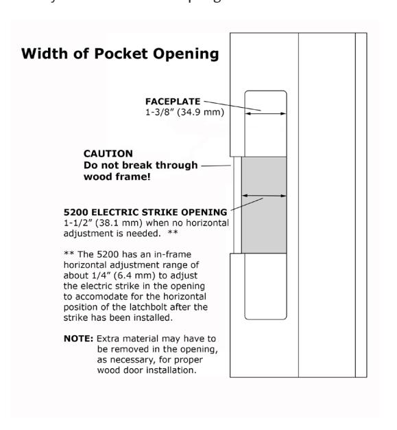
NOTE: The 5200 has an in-frame horizontal adjustment range of about 1/4" (6.4 mm) to allow adjustment of the electric strike in the frame opening to accommodate for the horizontal position of the latchbolt after the strike has been installed. The "Adjusting the Horizontal" section provides steps for this adjustment.
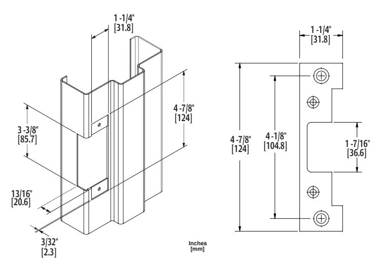
501 Faceplate Option (4-7/8" x 1-1/4"), Square Corners and Flat Faceplate Used with cylindrical locksets in ANSI metal jambs
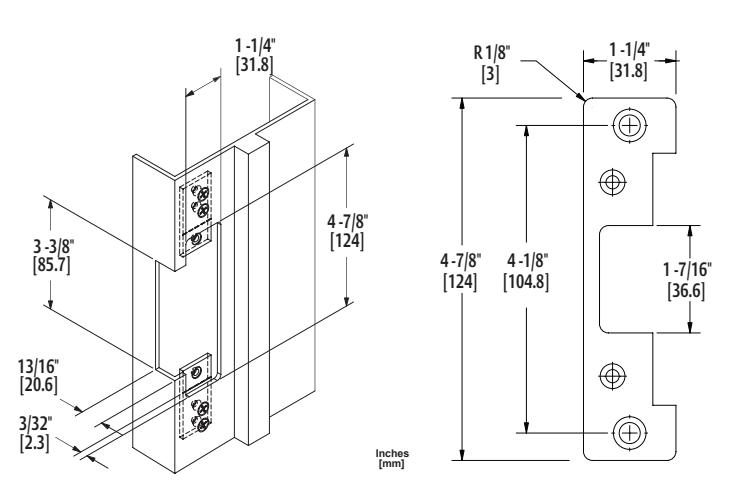
501A Faceplate Option (4-7/8" x 1-1/4"), Radius Corners and Flat Faceplate Used with cylindrical locksets or spring latches in aluminum frames
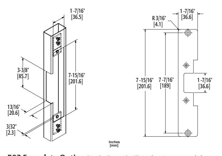
502 Faceplate Option (7-5/16" x 1-7/16"), Radius Corners and Flat Faceplate Used with cylindrical locksets or spring latches in aluminum frames
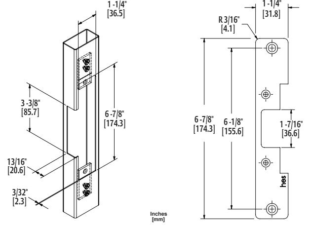
503 Faceplate Option (6-7/8" x 1-1/4"), Radius Corners and Flat Faceplate Used with cylindrical locksets or spring latches in aluminum frames
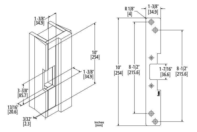
504 Faceplate Option (10" x 1-3/8"), Radius Corners and Flat Faceplate Used with cylindrical locksets; four-point mounting for wood installations
© 2015, Hanchett Entry Systems, Inc., an ASSA ABLOY Group company.

5200 Series Electric Strike
Installation Instructions
HES, Inc. Phoenix, AZ 800-626-7590 www.hesinnovations.com
Product Components
1 5200 Electric Strike Body
2 Trim Enhancer
3 12-Volt and 24-Volt Pigtails
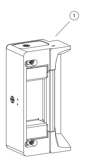
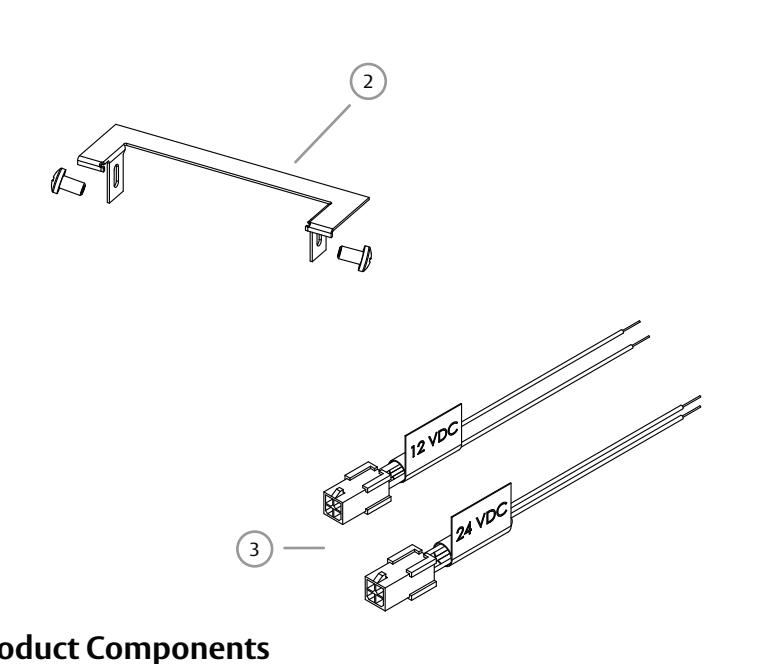
Diagram 1: Product Components
Electrical Specifications
| Electrical Ratings for Solenoid | ||||||
|---|---|---|---|---|---|---|
| Continuous Duty | 12 VDC | 24 VDC | Intermittent Duty* | 12–16 VAC | 24 VAC | |
| Resistance in Ohms | 50 | 200 | Resistance in Ohms | 50 | 200 | |
| Amps | .24 | .12 | Amps | .24 – .32 | .12 | |
Solenoids are rated at +/- 10% indicated value.
*10% maximum duty cycle (2 minutes maximum on time) Indoor use only
| Minimum Wire Gauge Requirements | Solenoid Voltage | ||
|---|---|---|---|
| (Based on Round Trip) | 12 VDC | 24 VDC | |
| 200 feet or less | 18 gauge | 20 gauge | |
| 200 – 300 feet | 16 gauge | 18 gauge | |
| 300 – 400 feet | 14 gauge | 16 gauge | |
ASSA ABLOY, the global leader in door opening solutions
2 Installation
CAUTION!
Before connecting any device at the installation site, verify input voltage using a multimeter. Many power supplies and low voltage transformers operate at higher levels than listed. Any input voltage exceeding 10% of the solenoid rating may cause severe damage to the unit and will void the warranty.
6. PREPARE the frame using the appropriate template
7. Electrically CONNECT the wires from the power
for the faceplate (see Page 4).
Preparing the Frame
Finishing the Installation
8. INSTALL the 5200 in the jamb cutout.
9. IF horizontal adjustment is needed,
THEN GO TO the "Adjusting the Horizontal"
source to the 5200.
section (see Page 3).
Preparing the Strike
Note: For 12 VDC, the Plug In Connector (pigtail) marked "12 VDC" should be used; for 24 VDC, the pigtail marked "24 VDC should be used.
- 1. SELECT the appropriate pigtail that matches system power and electrically CONNECT as illustrated in Diagram 2.
- 2. If no connector is present, CONFIGURE the wires as illustrated in Diagram 2.
- 3. If using the Latchbolt Monitor (LBM) or Latchbolt Strike Monitor (LBSM), REFER to Diagrams 3 and 4 on Page 3 to complete wiring.
Note: The 5200 ships in FAIL SECURE OPERATION mode.
4. USE Diagrams 5 and 6 on Page 3 as a guide to convert 5200 to FAIL SAFE OPERATION, if needed.
5. ATTACH the appropriate faceplate.
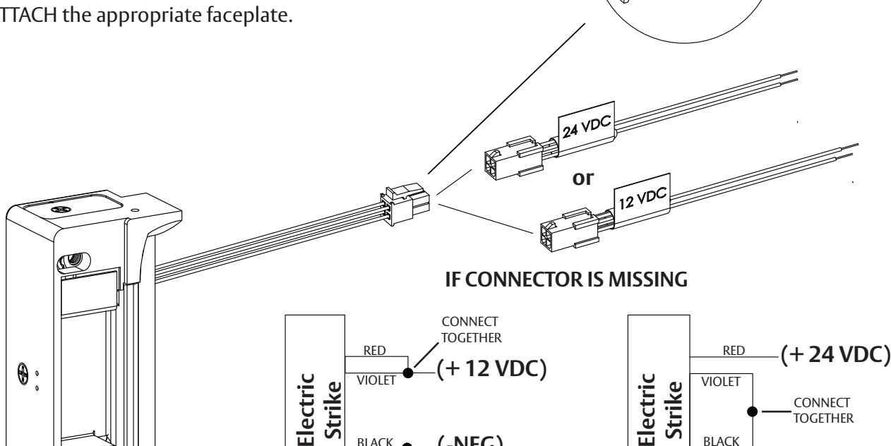
(-NEG)
CONNECT TOGETHER
RED/GREEN BLACK
Diagram 2: 12V to 24V Conversion
BLACK
RED/GREEN
(-NEG)
3 Installation (continued)
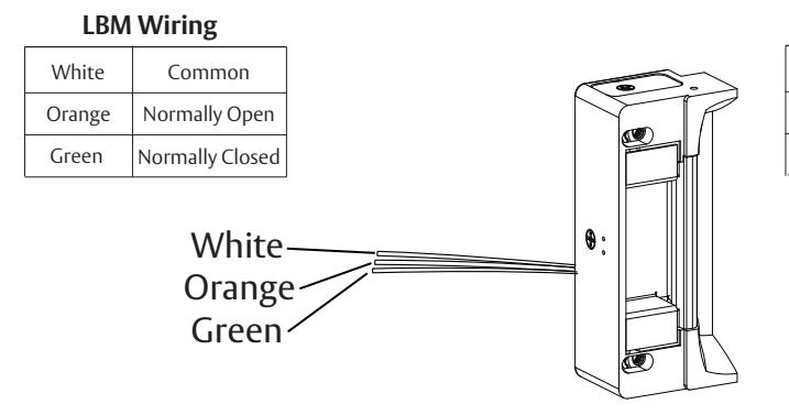
DIAGRAM 5: CYLINDRICAL LOCKSETS
Converting the Operation Mode
- Note 1: The 5200 series Electric Strikes are pre-set for FAIL SECURE OPERATION.
- Note 2: There are two #2-56 screws located on the back of the strike for coverting the operation mode.
- 10. To convert from FAIL SECURE OPERATION to FAIL SAFE OPERATION, LOOSEN the two #2-56 screws located on the back of the strike, but DO NOT REMOVE them.
- 11. MOVE the Selector Stop Pins to the FAIL SAFE OPERATION position as pictured in Diagram 5.
- 12. TIGHTEN the two #2-56 screws to secure the strike in FAIL SAFE OPERATION.
Verifying the Operation Mode
- 13. VERIFY the 5200 is now in FAIL SAFE OPERATION.
- 14. IF the 5200 still operates as FAIL SECURE, THEN ENSURE the #2-56 screws are fully seated and tightened.
Adjusting the Horizontal
- 15. TURN the horizontal adjustment screws slowly to adjust the strike in-frame, as shown in Diagram 6.
- 16. DO NOT REMOVE the screws or ROTATE them more than 3 full turns.
- 17. TIGHTEN the screws securely once the strike has been adjusted to allow the K-Nut teeth to dig into the strike housing and prevent slippage during use.
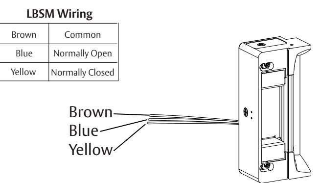
Diagram 3: Latchbolt Monitor Diagram 4: Latchbolt Strike Monitor
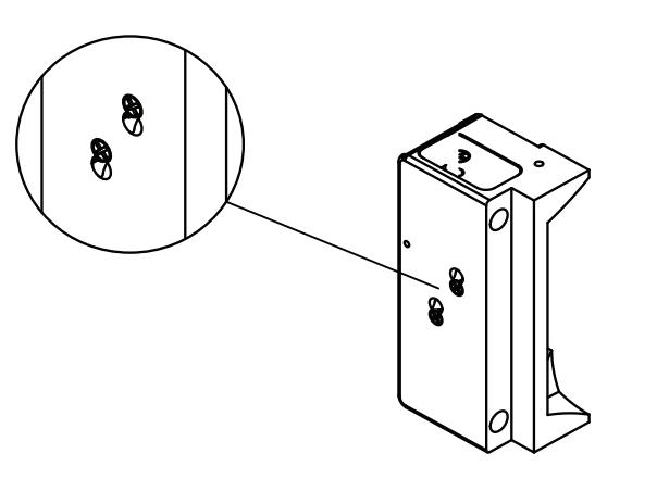
Diagram 5: FAIL SAFE OPERATION Mode Setting
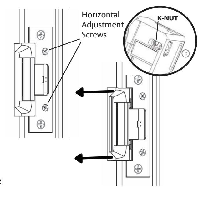
Diagram 6: Horizontal Adjustment