HES 4500C Series Complete Pacs for Latchbolt Locks Electric Installation Instructions
Open the original PDF document
View PDFInches [Millimeters]
4
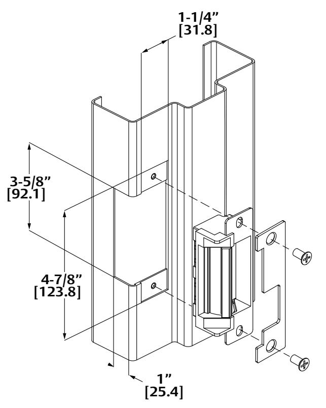
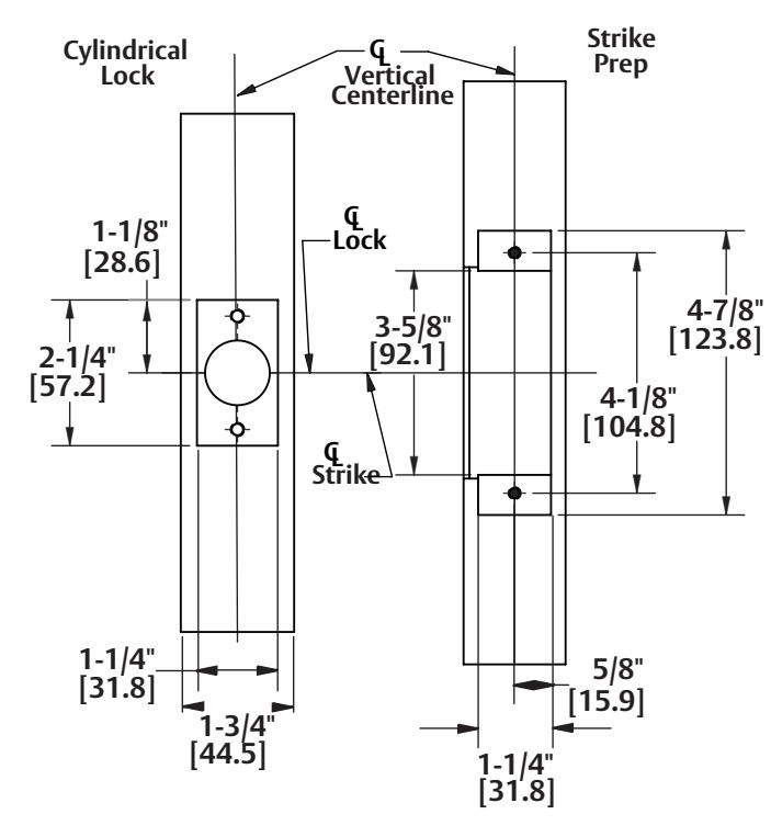
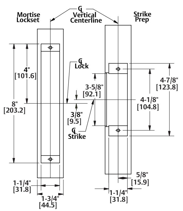
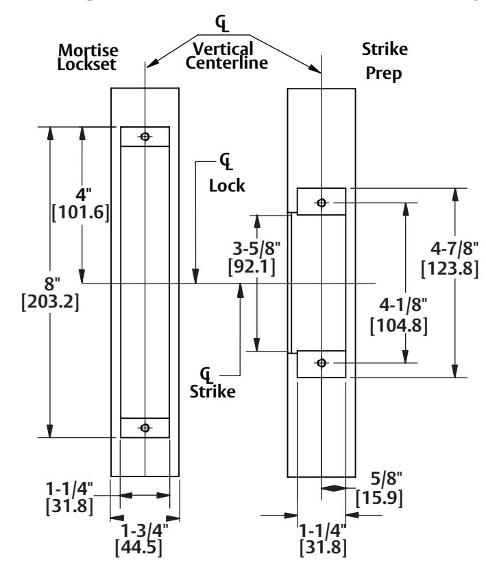
JAMB Cutout Dimensions
4500 with Cylindrical Locksets
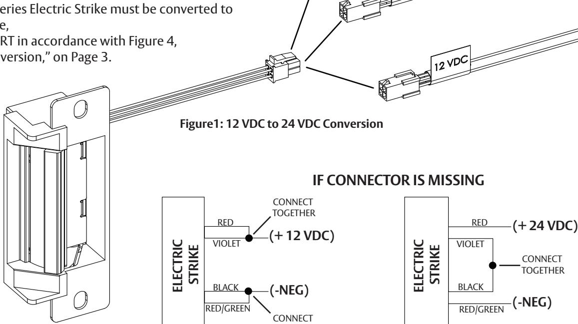
4500 with Mortise Locksets
Schlage L9000 and YALE 8700 Locks Only
3053006.002 rev C
© 2015, Hanchett Entry Systems, Inc., an ASSA ABLOY Group company.

4500 Series Electric Strike Installation Instructions
HES, Inc. Phoenix, AZ 800-626-7590 www.hesinnovations.com
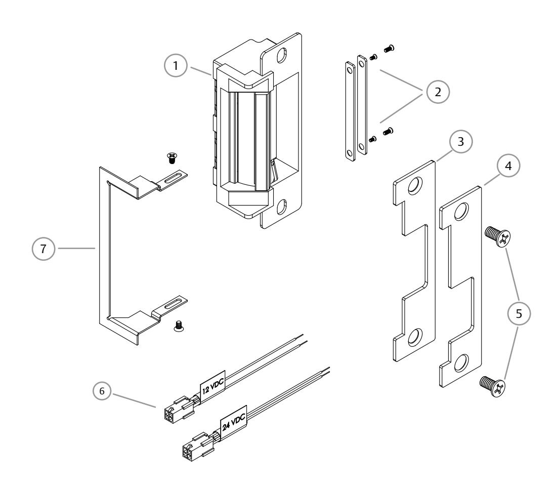
Product Components
- 1 4500 Electric Strike Body
- ② Keeper Shims & Screws (#4-40 x 1/8" and #4-40 x 3/16")
- 3 Centerlined and Non-handed Faceplate for Cylindrical Locksets
- 4 Offset and Non-handed Faceplate for Mortise Locksets
- 5 #12-24 x 1/2" Mounting Screws
- 6 12 & 24 Volt Plug In Connectors
- 7 Trim Enhancer & Screws
Electrical Specifications
| ELECTRICAL RATINGS FOR SOLENOID | CONTINUOUS DUTY | INTERMITTENT DUTY* | ||
|---|---|---|---|---|
| 12 VDC | 24 VDC | 12–16 VAC | 24 VAC | |
| Resistance in Ohms | 50 | 200 | 50 | 200 |
| Amps | .24 | .12 | .24.–.32 | .12 |
Solenoids are rated at +/- 10% indicated valu *10% max duty cycle (2 min. max on time)
| MINIMUM WIRE GAUGE REQUIREMENTS | SOLENOID VOLTAGE | |
|---|---|---|
| 12VDC | 24VDC | |
| 200 feet or less | 18 gauge | 20 gauge |
| 200 - 300 feet | 16 gauge | 18 gauge |
| 300 - 400 feet | 14 gauge | 16 gauge |
ASSA ABLOY, the global leader in door opening solutions
Installation Directions 2
CAUTION!
Before connecting any device at the installation site, verify input voltage using a multimeter. Many power supplies and low voltage transformers operate at higher levels than listed. Any input voltage exceeding 10% of the solenoid rating may cause severe damage to the unit and will void the warranty.
Preparing the Strike
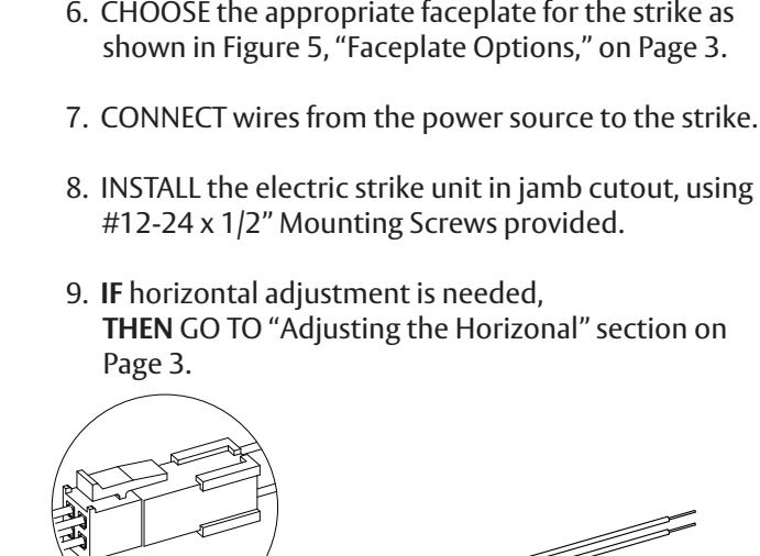
NOTE 1: For 12 VAC, 12 VDC, or 16 VAC, the pigtail marked "12 VDC" is used.
NOTE 2: For 24VAC or 24 VDC, the pigtail marked "24 VDC" is used.
1. SELECT the appropriate plug in connector that matches system power and electrically CONNECT as shown in Figure 1, "12 VDC to 24 VDC Conversion."
NOTE: The state of switch is listed for an unpowered strike and LBM in unactuated (door open) position.
2. IF using a Latchbolt Monitor (LBM) or Latchbolt Strike Monitor (LBSM), THEN COMPLETE wiring in accordance with Figures 2, "Latchbolt Monitor," and Figure 3, "Strike Monitor," on Page 3.
CAUTION
Converting the 4500 Series Strike to Fail Safe Mode negates the unit's fire rating.
NOTE: This unit ships in Fail Secure mode.
- 3. VERIFY that the strike is in the correct mode of operation.
- 4. IF the 4500 Series Electric Strike must be converted to Fail Safe mode,
THEN CONVERT in accordance with Figure 4, "Fail Safe Conversion," on Page 3.
Finishing the Installation
cutout template, as shown on Page 4.
Preparing the Frame
NOTE: Schlage L9000 and Yale 8700 locksets must use the template labeled "Schlage L9000 & Yale 8700 Locks Only." All other locksets should use the template labeled "Cylindrical Lockset" or Mortise Lockset."
5. PREPARE the frame for lockset using appropriate
TOGETHER
Installation (continued) 3
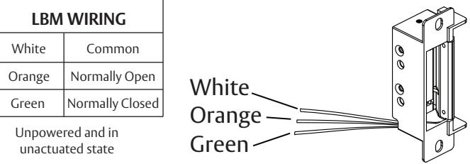
Figure 2: Latchbolt Monitor Figure 3: Strike Monitor
Figure 4: Fail Safe Conversion
NOTE 1: A Non-handed offset faceplate is provided for use with mortise locksets. The mortise lock deadlatch should be depressed by the faceplate when the door is closed.
NOTE 2: A Non-handed center-lined faceplate is provided for use
1 2
with cylindrical locksets.
Fire Door Safety Screw
Figure 5: Faceplate Options
| LBSM WIRING | |||
|---|---|---|---|
| Brown | Common | ||
| Blue | Normally Open | ||
| Yellow Normally Closed | |||
|
Unpowered and in
unactuated state |
|||
Brown Blue Yellow
Converting the Operation Mode 10. REMOVE the Fire Door Safety Screw as shown in Figure 4.
- 11. LOOSEN the two #2-56 screws located on the back of the strike, but DO NOT REMOVE them.
- 12. MOVE screws from the bottom of the hole (Fail Secure mode position) to the top hole (Fail Safe mode position).
- 13. TIGHTEN the bottom screw first (wire side), and THEN TIGHTEN the top screw.
- 14. VERIFY the strike is now in the Fail Safe operation mode.
- 15. IF the strike still operates as Fail Secure, THEN ENSURE the screws are fully seated in the top position.
Adjusting the Horizontal
- 16. IF horizontal adjustment is needed, THEN ADD 1 or 2 keeper shims as shown in Figure 6, "Horizontal Adjustment."
- a. USE the #4-40 x 1/8" keeper shim screws if adding one shim.
- b. USE the #4-40 x 3/16" keeper shim screws if adding two shims.
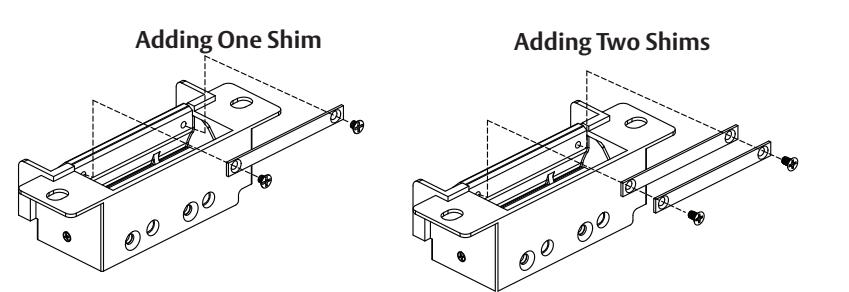
Figure 6: Horizontal Adjustment