HES 2005M3 Smart Pac III Installation Instructions
Open the original PDF document
View PDF

Installation Instructions 2005M3 SMART Pac III™
HES, Inc. 22630 N. 17th Ave. Phoenix, AZ 85027 800-626-7590 www.hesinnovations.com
Overview
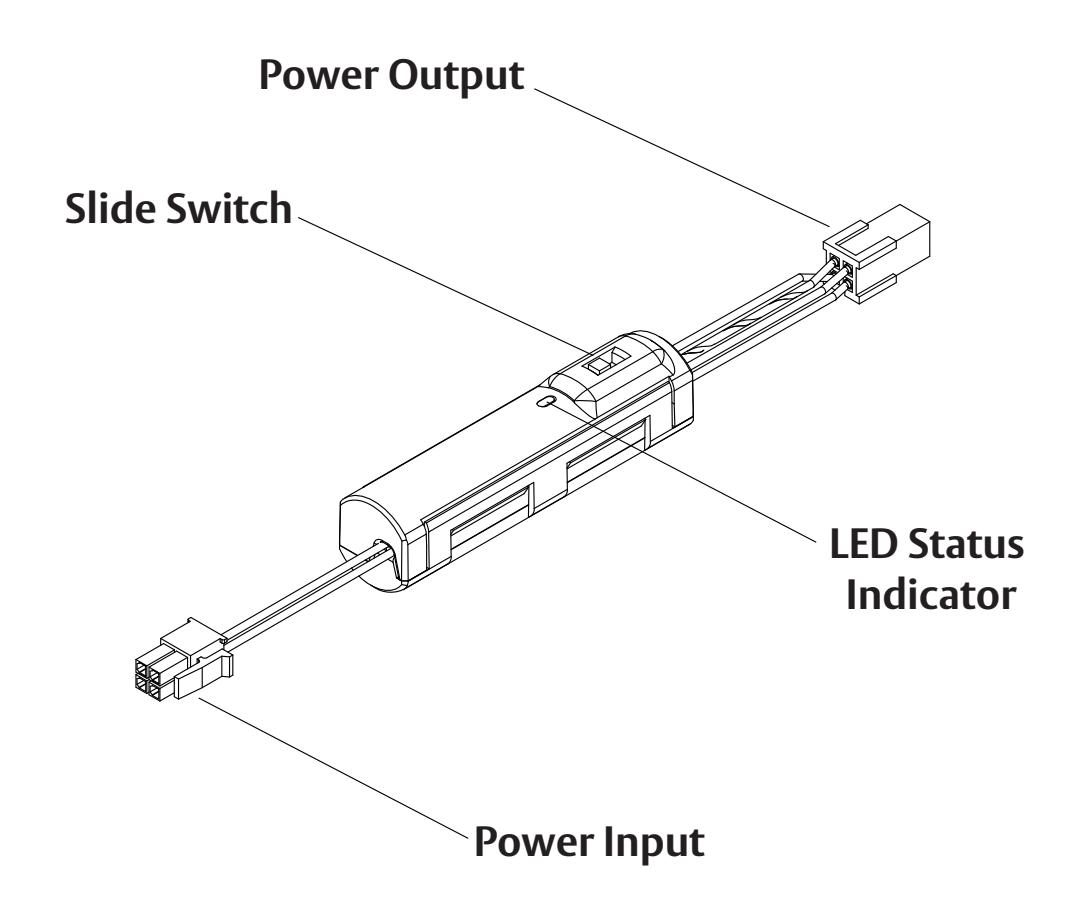
The SMART Pac III is an in-line power controller designed to protect and extend the life of HES electric strikes and other ASSA ABLOY electrified products. The built-in poly switch and zener diode protect the host system from possible reverse current surges, while a reduced voltage 'step down' extends the life of the electric strike by reducing operating temperature. The SMART Pac III can provide a DC output with an input ranging from 10.5 to 33 VDC or 10.5 to 30 RMS AC.
The SMART Pac III can also be used to troubleshoot installation problems. The SMART Pac III's built-in LED can be used as a simplified voltage meter that indicates the power supply voltage at the installation. In addition, the SMART Pac III has a two-position Slide Switch that matches the SMART Pac III output voltage to the operating voltage of the electric strike. Note: The input voltage must be in range of the voltage required by the electric strike.
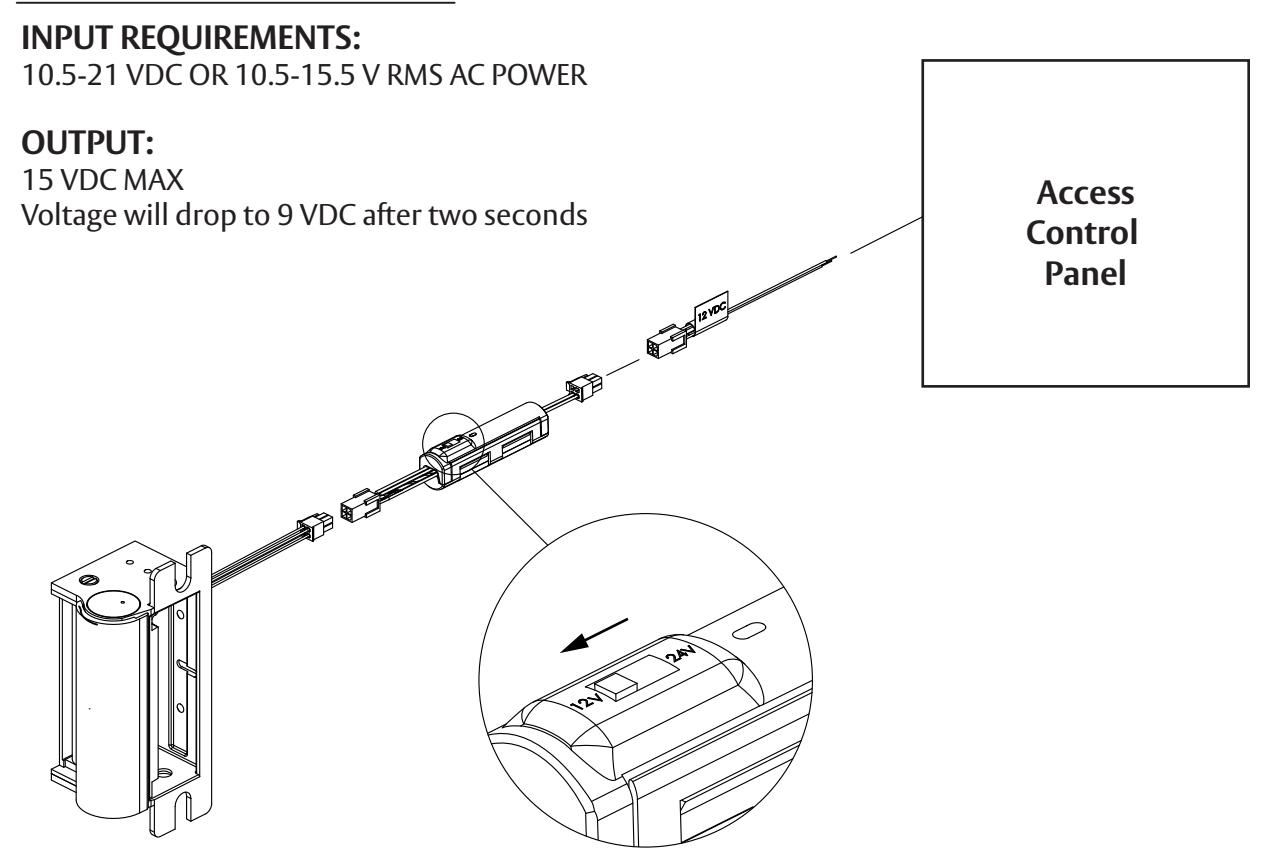
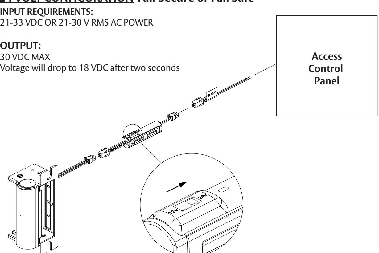
- 1. Connecting the SMART Pac III: Connect the SMART Pac III to the wires coming from the access control panel as shown on Page 3, using either the 12V or 24V pigtail provided with the HES electric strike. If using other ASSA ABLOY electrified products, refer to the wiring schematic on Page 4.
- 2. Using SMART Pac III to confirm correct input voltage: Set the SMART Pac's slide switch to the voltage of the power supply (see Page 3) and activate power. The behavior of the SMART Pac's LED Status Indicator will communicate the following:
- Voltage input, and if it is within the input requirements listed on Page 3
- Correct position of the the SMART Pac's slide switch for the voltage input
- 3. Resolving Fault Codes: A blinking or unlit LED indicates corrective action is needed.
- a. Using the LED STATUS INDICATOR TABLE below determine the appropriate corrective action.
- b. Remove power to the SMART Pac III and correct the error condition.
- c. Wait 10 seconds and re-power the unit. This will reset the LED indicator.
Warning: The slide switch configures the wiring to the electric strike. It does not control the SMART PAC III's voltage output and will not prevent an overload condition if set improperly. The voltage rating of the electric strike must match the voltage output of the power supply (e.g.: Use a 24 Volt strike if you have a power supply rated at 24 Volts.)
If using an electric strike and/or additional devices in series with a single SMART PAC III, do not exceed a current rating of 750 MA at 25 C.
4. Connecting the Electric Strike: With no power supplied to the SMART Pac III, connect the electric strike. Verify the operation of the electric strike and a steady LED color when power is present.
LED STATUS INDICATOR TABLE
| LED COLOR | INPUT CONDITION | OUTPUT CONDITION | CORRECTIVE ACTION | |
|---|---|---|---|---|
| 1 | Steady Green | 10.5-21V* | 15 VDC MAX STEPPING TO 9 VDC | NONE REQUIRED |
| 2 | Steady Yellow | 21-33V* | 30 VDC MAX STEPPING TO 18 VDC | NONE REQUIRED |
| 3 | Off or Blinking Green | TOO LOW (min. 10.5V) | ~ 0 | INCREASE VOLTAGE |
| 4 | Blinking Yellow | TOO HIGH (>33V) | ~ 0 | DECREASE VOLTAGE |
| 5 | Blinking 2 Yellow/2Green | ANY | WRONG SLIDE SWITCH POSITION | CHANGE SLIDE SWITCH POSITION |
| 6 | Blinking Yellow/Green | ANY | DOWNSTREAM SHORT | FIND AND REMOVE SHORT |
* See input requirements on Page 3
NOTE: A self re-setting poly switch is built into the SMART Pac III to prevent damage to the electric strike in an over-current situation or downstream short. Normally, the SMART Pac III will detect over current situations and shut down the power output before the poly switch opens. If the poly switch trips there will be no voltage output and no LED status.
12 VOLT CONFIGURATION-Fail Secure or Fail Safe
24 VOLT CONFIGURATION-Fail Secure or Fail Safe
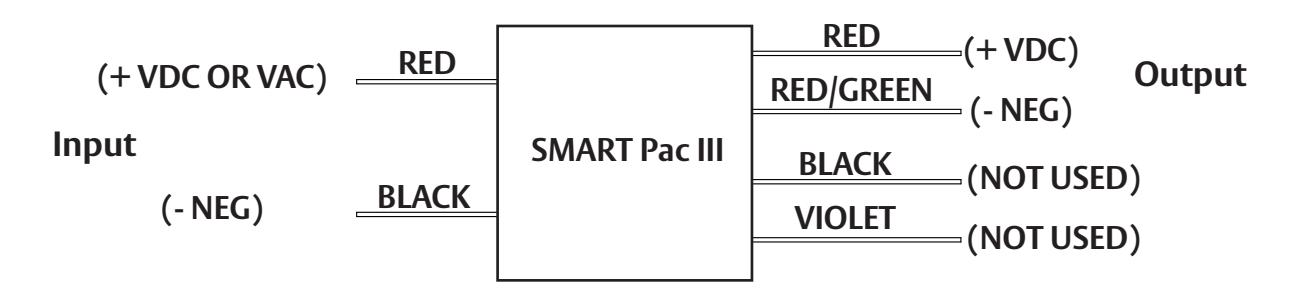
If the SMART Pac III is being used with ASSA ABLOY electrified products check to make sure the electrified product or products do not have a current rating exceeding 750 mA at 25 degrees C. Remove the SMART Pac III molex connectors and connect wires as illustrated in the diagram below.
Note: After modifying, please cap the Black and Violet wires independently to prevent electrical shorting within the frame. Also, verify device is within the current limitations specified on page 2.
If Connectors are Removed
3027006.008 rev A © 2010 HES, Inc.