HC980, 12-HC980, HD980 and 12-HD980 Mullion Instruction Sheet
Open the original PDF document
View PDFHC980, 12-HC980, HD980 and 12-HD980 Series
Mullions
Tools Required
- Tape Measure
- Pencil
- #3 Phillips Head Screwdriver
- Hammer
- Punch
- #7 Drill and 1/4"-20 Tap
- 3/8" Concrete Drill
- 1/2" Drill

WARNING
This product can expose you to lead which is known to the state of California to cause cancer and birth defects or other reproductive harm. For more information go to www.P65warnings.ca.gov.
NOTES:
- Verify product number.
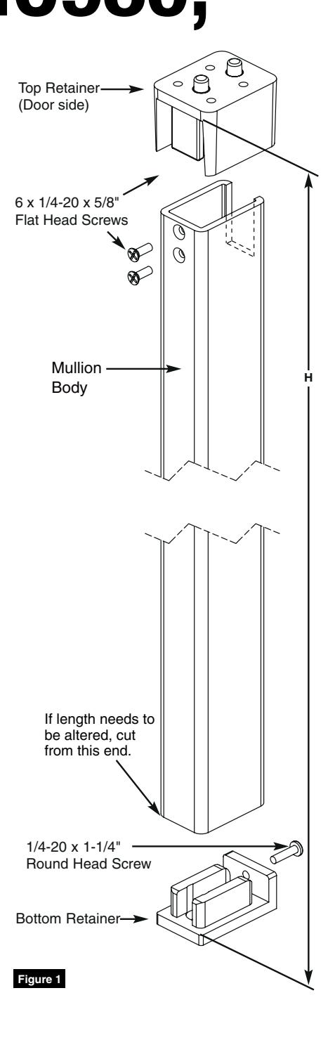
- Make sure doors are properly installed and hinge screws are secure. Figure 1
HC980, 12-HC980, HD980 and 12-HD980 Series
Mullions
Installation Instructions

1 Attach Top Retainer To Top Jamb
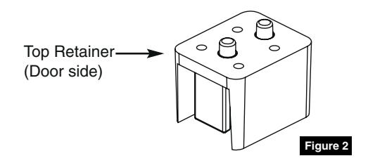
- 1. Mark centerline of top retainer (Figure 2) on top jamb.
- 2. Close doors and keep door leaves tight to stops.
- 3. Fold supplied template No. MEMN9 along the creased line and locate on top jamb using centerline marked. Attach template to frame and doors with self-adhesive strips supplied.
- 4. Mark, drill and tap holes required.
- 5. Install top retainer using four (4) 1/4- 20 x 5/8" flat head screws. (Figure 1 on page 1)
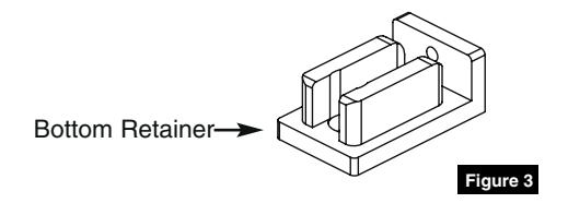
2 Locate Bottom Retainer On Floor
(Figure 3)
NOTE:
Do not attach retainer to floor in this step.
3 Cut Mullion Body To Size
- 1. Measure distance (H) between inside surface of top retainer and top of bottom retainer surface. (Figure 1 on page 1)
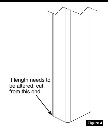
- 2. Cut off bottom of mullion body to desired length (L), using formula: L = H - 1/16"
HC980, 12-HC980, HD980 and 12-HD980 Series
Mullions
Installation Instructions

4 Position Mullion
- 1. Position mullion body into bottom and top retainers and locate vertically.
- 2. Mark bottom retainer location on floor (Bottom retainer is not installed.)
NOTE:
Make sure mullion surface engages with doors so it is plumb to door face and frame.
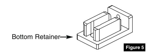
5 Install Bottom Retainer
- 1. Remove mullion body from retainers and put aside.
- 2. Align bottom retainer (Figure 5) with previous markings from Step 4.
- 3. Use a punch and hammer to mark hole locations on floor.
- 4. Drill two (2) 3/8" diameter holes in floor to a minimum depth of 2-5/8".
- 5. Mount bottom retainer to floor with supplied two (2) 3/8" fasteners.
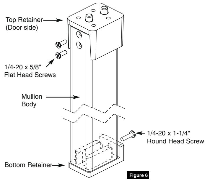
6 Install Mullion Body
- 1. Position mullion body first into bottom retainer, then top retainer.
- 2. Drill and tap two (2) 1/4-20 holes in top retainer through countersunk holes in mullion body.
- 3. Install two (2) 1/4-20 x 5/8" flat head screws. (Figure 6)
- 4. Drill and tap one (1) 1/4-20 hole in bottom end of mullion body through hole in bottom retainer.
- 5. Install one (1) 1/4-20 x 1-1/4" round head screw. (Figure 6)

7 Install Exit Devices
1. Refer to manufacturer's instructions.
SARGENT Manufacturing Company 100 Sargent Drive New Haven, CT 06511 USA 800-727-5477 www.sargentlock.com
Founded in the early 1800s, SARGENT® is a market leader in locksets, cylinders, door closers, exit devices, electro-mechanical products and access control systems for new construction, renovation, and replacement applications. The company's customer base includes commercial construction, institutional, and industrial markets.
Copyright © 2018, SARGENT Manufacturing Company. All rights reserved. Reproduction in whole or in part without the express written permission of SARGENT Manufacturing Company is prohibited.