Glynn-Johnson_HL6_Push_Pull_Latch_Installation_Instructions_107562
Open the original PDF document
View PDF

HL6

829694-00 Push/Pull Latch
Installation Instructions

1 Install Latch
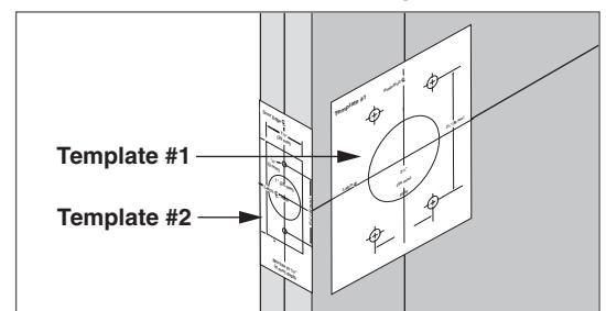
- 1a Use templates from back page to check holes.
- NOTE: If door holes do not match template, see the Door Preparation section on the next page.
1b For HL6L (lead lined) ONLY, install lead lining.

1c Install latch.

1d Position cams, as shown.

1e Install push lever and pull lever.

1f Place covers over levers. Install and tighten lever and cover screws.

- 1g Install strike.
- (i) NOTE: If frame is not prepared, see Frame Preparation on the next page.


2 Frame Preparation
2a Use strike as a pattern to mark the frame.

2b Drill holes.

2c Mortise for strike.
i NOTE: Strike should be flush to frame.

3 Door Preparation
3a Mark center lines.

3b Mark the door.

OR

3c Drill holes, per the template.

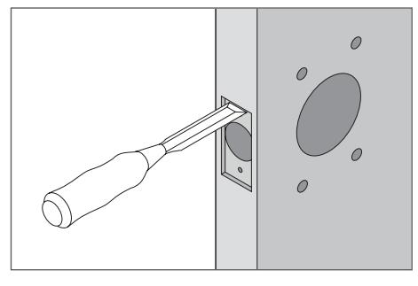
3d Mortise for the latch, per the template.


BEGINNING SHEET FINAL SIZE
| Additional Notes: | |
|---|---|
| Printed saddle-stitched booklet | А |
| N/ | |
| Mate | |
|
Note
1. pr 2. Fc 2. pr 3. to 4. pr 5. dr |
| Revision History | Revision Description: | ||||||||||
|---|---|---|---|---|---|---|---|---|---|---|---|
| А | В | С | D | Е | F | E > Revised artwork | |||||
| N/A | N/A | N/A | 075349 | xxxxxx | 1 | ||||||
| Material | Edited By | Approved By | EC Number | Release Date | |||||||
| White Paper | D. Toppins | M. Sasso | xxxxx | 05-09-18 | |||||||
|
Notes
1. printed two sides 2. Folded booklet style |
Title INSTALLATION INSTRUCTIONS HL6 PUSH/PULL LATCH | ||||||||||
| 2. printed black 3. tolerance ± .13 4. printed in country may vary |
Creation Date
07-20-15 |
Number 829694-00 |
Revision
E |
||||||||
| 5. drawings not to scale |
Created By
N/A |
Activity
3899 Hancock Expwy Security, CO 80911 |
|||||||||
| Software: InDesign CS6 | Allegion 2018 | ||||||||||