Glynn Johnson 90 Series Surface Overhead Holders with Angle Bracket for Flush Frame H F S SE Installation Instructions 108151
Open the original PDF document
View PDF

INST.90J
Surface Overhead Holders with Angle Bracket for Flush Frame
Installation Instructions
These instructions cover the following models: 90H (Hold Open), 90S (Stop only), 90F (Friction), and 90SE (Special Stop Only)
INSTALLATION NOTES
- Hollow metal frames should be properly reinforced with a 3/16" (5mm) minimum thickness by 12" (305mm) minimum length plate. 1.
- Hollow metal doors should be properly reinforced with a 3/16" (5mm) minimum thickness by 2-1/2" (64mm) minimum width plate. 2.
- Stop only units are permitted on many fire door applications. However, mechanical hold-open devices that require manual release are not permitted for use on any fire door as outlined on NFPA80 ® or NFPA101 ® . Contact Glynn Johnson or your local representative for assistance. 3.
ADJUSTMENTS Hold-open tension adjustment (Hold-open model only): Using a phillips screwdriver, turn screw shown clockwise to increase hold-open tension and counterclockwise to decrease hold open tension. Friction adjustment (Friction model only): Using a 3/32" hex wrench, turn screw shown clockwise to increase friction and counterclockwise to decrease friction. Hold-open tension adjustment screw Friction adjustment screw


INSTALLATION STEPS
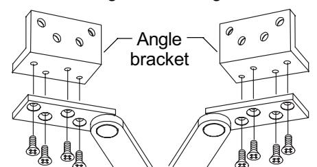
Install angle bracket on closer. Note: Flip bracket as needed so that mounting surface is against frame.

| identity correct mounting group to use on chart. | ||||||||
|---|---|---|---|---|---|---|---|---|
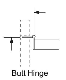
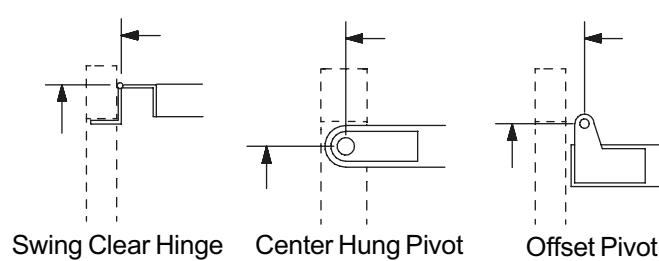
| Hinge Type & Size |
Mounting
Group |
|||||||
| Butt Hinge 4" Wide | 3 | |||||||
| Butt Hinge 4-1/2" Wide | 2 | |||||||
| Butt Hinge 5" Wide | 1 | |||||||
| Swing Clear Hinge 4" Wide | 1 | |||||||
| Swing Clear Hinge 4-1/2" Wide (1-3/4" door) | 3 | |||||||
| Swing Clear Hinge 4-1/2" Wide (2" door) | 2 | |||||||
| Swing Clear Hinge 4-1/2" Wide (2-1/4" door) | 1 | |||||||
| Swing Clear Hinge 5" Wide (1-3/4" door) | 3 | |||||||
| Swing Clear Hinge 5" Wide (2" door) | 2 | |||||||
| Swing Clear Hinge 5" Wide (2-1/4" door) | 1 | |||||||
| Center Hung Pivot (1-3/4" - 2-1/4" doors) | 4 | |||||||
| 3/4" Offset Pivot (1-3/8" door) | 3 | |||||||
| 3/4" Offset Pivot (1-3/4" door) | 2 | |||||||
| 3/4" Offset Pivot (2" or 2-1/4" door) | 1 | |||||||
| SOSS 220 (2" or 2-1/4" door) | 2 | |||||||
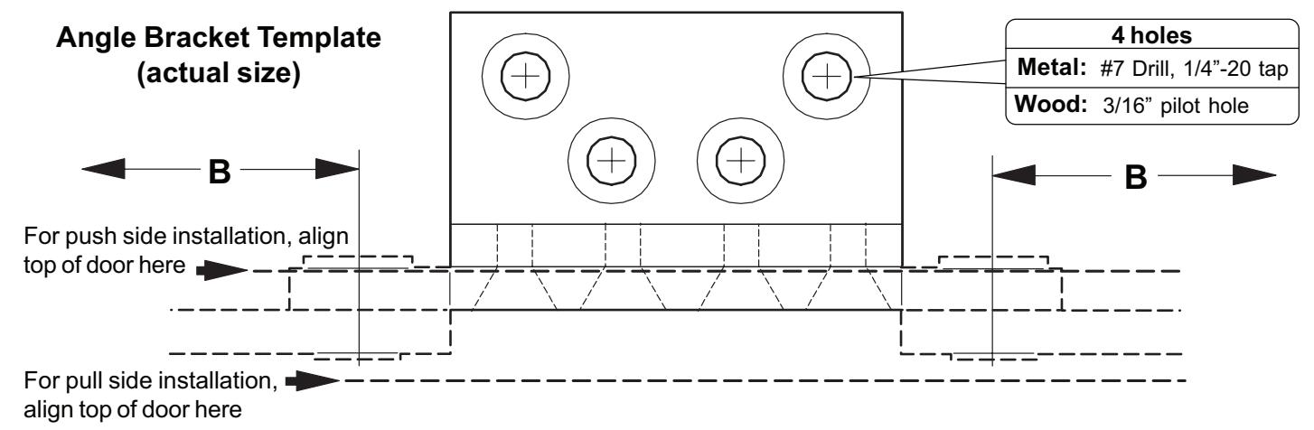
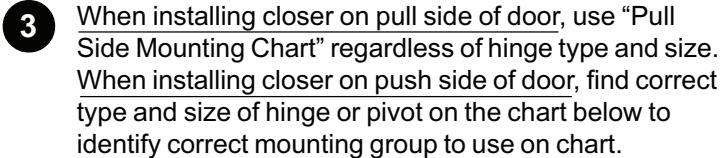
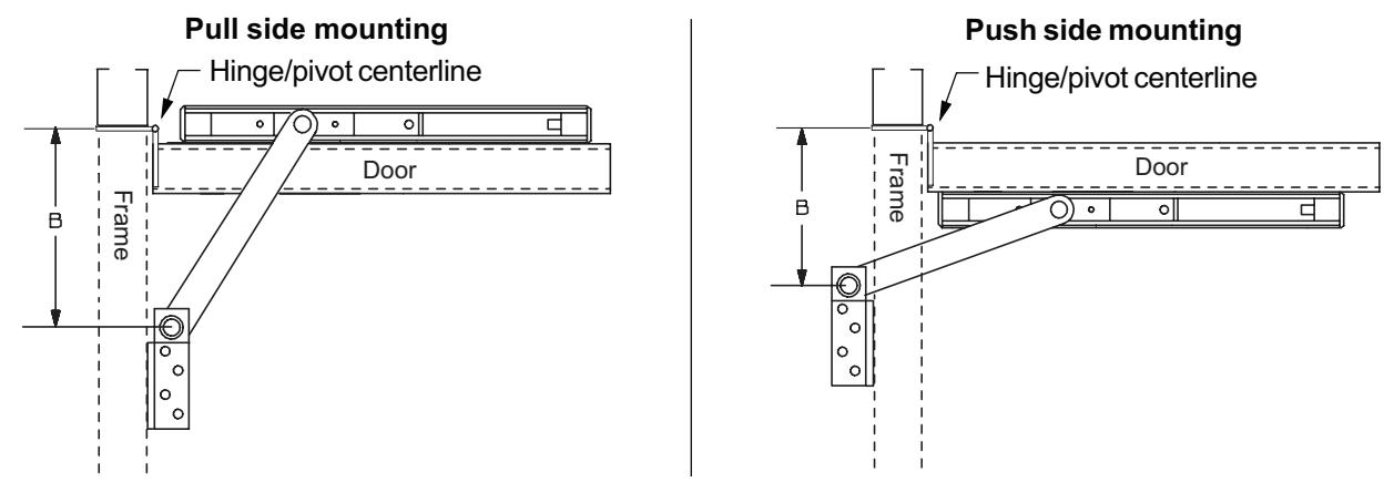
Dimensions A, B, and C (shown below) will be used to locate holder on door and frame.
5 Using the mounting group and GJ model numbers, find dimensions "A", "B", and "C" on page 3 chart.
Notes on using chart:
- "Degrees" shown on chart represent desired hold-open degree (on hold-open, friction, and stop only models) or stop degree (on SE models).
- "I" = Arm length from center to center (for reference only).
- On hold-open, friction, and stop only models, the dead stop (DS) degree is normally 5-7 degrees beyond the hold-open degree shown on chart. The DS door position is reached when the shock spring is fully compressed.
- When installing on doors which open back-to-back, or against a wall or obstruction, it may be desirable to install the holder based on the dead stop angle rather than the hold-open angle. To do this, add 13/16" (21mm) to the "A" dimension on chart. This will effectively reduce the dead stop and hold-open by 5-7 degrees. This can only be done on hold-open, friction, and stop only models, but NOT on SE models.
CAUTION : "A" & "B" dimensions are measured from the centerline of hinge, not edge of door. * Not to be used with swing clear hinges.
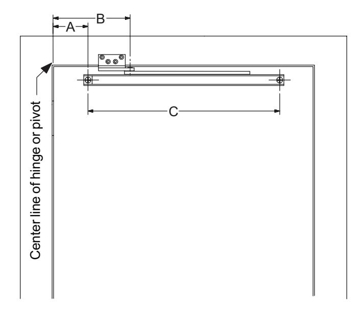
Push Side Mounting Chart
| 85 degrees | 90 degrees | 95 degrees | 100 degrees | 105 degrees | 110 degrees | |||||||||||
|---|---|---|---|---|---|---|---|---|---|---|---|---|---|---|---|---|
Pull Side Mounting Chart
| 85 degrees | 90 degrees | 95 degrees | 100 degrees | 105 degrees | 110 degrees | ||||
|---|---|---|---|---|---|---|---|---|---|
Mark "B" dimension (from chart) on frame. Note that "B" dimension is measured from centerline of hinge as shown. 6
- 7 Cut out "Angle Bracket Template" from bottom of page and align on frame to locate 4 holes to drill.
- Locate and mark "A" and "C" dimensions on door. Note that "A" dimension is measured from centerline of hinge as shown. For dead stop add 13/16" (21mm) to the "A" dimension from the chart. For more information about dead stop, see page 2 under "Notes on using chart". 8
- Drill two 3/8" (10mm) diameter channel mounting holes through door per chart and dimensions shown below. Mounting holes should be prepared only after door and frame are installed. 9
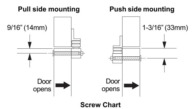
- Install jamb bracket on the stop (see Screw Chart). 10
- Install the channel on the door (see Screw Chart) Shock spring should be located on hinge end of the door. 11
| QTY | Screw type | Wood Metal | ||
|---|---|---|---|---|
| 4 | #14 x 1-1/2" FPHSMS | |||
| Jamb | 4 | 1/4"-20 x 3/4" FPHMS | ||
| 2 | 1/4"-20 x 1-1/4" OPHMS | |||
| Door | 2 | 1/4"-20 x 2-1/2" Sex bolts | ||
|
Angle
Brkt. |
4 | 1/4"-20 x 1/2" |