Glynn Johnson 90 Series Surface Overhead Holders H F S SE Installation Instructions 101408
Open the original PDF document
View PDF

Surface Overhead Holders
Installation Instructions
These instructions cover the following models: 90H (Hold Open), 90S (Stop only), 90F (Friction), and 90SE (Special Stop Only)
INSTALLATION NOTES
- Hollow metal frames should be properly reinforced with a 3/16" (5mm) minimum thickness by 12" (305mm) minimum length plate. 1.
- Hollow metal doors should be properly reinforced with a 3/16" (5mm) minimum thickness by 2-1/2" (64mm) minimum width plate. 2.
- Stop only units are permitted on many fire door applications. However, mechanical hold-open devices that require manual release are not permitted for use on any fire door as outlined on NFPA80 ® or NFPA101 ® . Contact Glynn Johnson or your local representative for assistance. 3.
ADJUSTMENTS Hold-open tension adjustment (Hold-open model only): Using a phillips screwdriver, turn screw shown clockwise to increase hold-open tension and counterclockwise to decrease hold open tension. Friction adjustment (Friction model only): Using a 3/32" hex wrench, turn screw shown clockwise to increase friction and counterclockwise to decrease friction. Hold-open tension adjustment screw Friction adjustment screw


INSTALLATION STEPS
1 Determine what type of hinge or pivot is being used on the door as shown below.
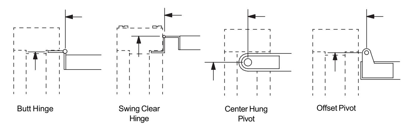
Find correct type and size of hinge or pivot on the chart below to identify correct mounting group.
| Hinge Type & Size |
Mounting
Group |
|---|---|
| Butt Hinge 4" Wide | 3 |
| Butt Hinge 4-1/2" Wide | 2 |
| Butt Hinge 5" Wide | 1 |
| Swing Clear Hinge 4" Wide | 1 |
| Swing Clear Hinge 4-1/2" Wide (1-3/4" door) | 3 |
| Swing Clear Hinge 4-1/2" Wide (2" door) | 2 |
| Swing Clear Hinge 4-1/2" Wide (2-1/4" door) | 1 |
| Swing Clear Hinge 5" Wide (1-3/4" door) | 3 |
| Swing Clear Hinge 5" Wide (2" door) | 2 |
| Swing Clear Hinge 5" Wide (2-1/4" door) | 1 |
| Center Hung Pivot (1-3/4" - 2-1/4" doors) | 4 |
| 3/4" Offset Pivot (1-3/8" door) | 3 |
| 3/4" Offset Pivot (1-3/4" door) | 2 |
| 3/4' Offset Pivot (2" or 2-1/4" door) | 1 |
| SOSS 220 (2" or 2-1/4" door) | 2 |
Dimensions A, B, and C (shown below) will be used to locate holder on door and frame.
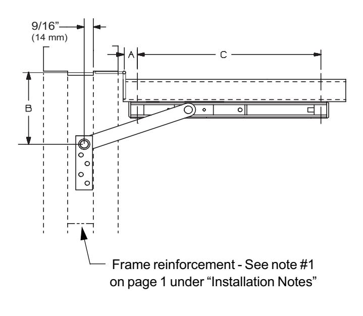
4 Using the mounting group and GJ model numbers, find dimensions "A", "B", and "C" on page 3 chart.
Notes on using chart:
- "Degrees" shown on chart represent desired hold-open degree (on hold-open, friction, and stop only models) or stop degree (on SE models).
- "I" = Arm length from center to center (for reference only).
- On hold-open, friction, and stop only models, the dead stop (DS) degree is normally 5-7 degrees beyond the hold-open degree shown on chart. The DS door position is reached when the shock spring is fully compressed.
- When installing on doors which open back-to-back, or against a wall or obstruction, it may be desirable to install the holder based on the dead stop angle rather than the hold-open angle. To do this, add 13/16" (21mm) to the "A" dimension on chart. This will effectively reduce the dead stop and hold-open by 5-7 degrees. This can only be done on hold-open, friction, and stop only models, but NOT on SE models.
CAUTION : "A" & "B" dimensions are measured from the centerline of hinge, not edge of door.
| 85 degrees | 90 degrees | 95 degrees | 100 degrees | 105 degrees | 110 degrees | ||||||
|---|---|---|---|---|---|---|---|---|---|---|---|
* Not to be used with swing clear hinges.
- Mark "B" dimension (from chart) on frame. Note that "B" dimension is measured from centerline of hinge as shown.
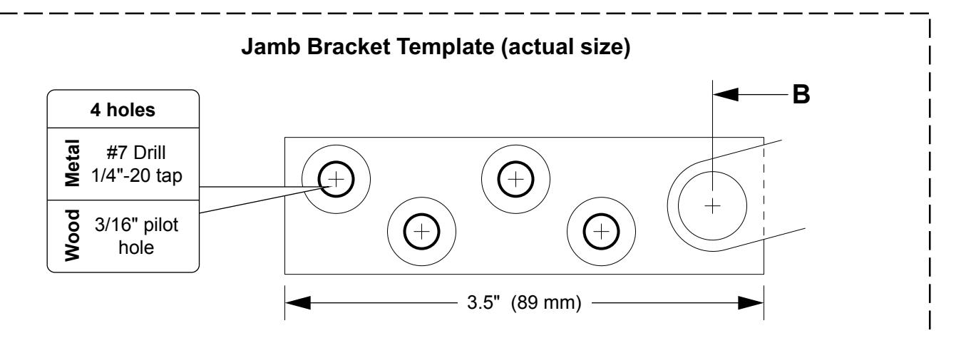
- 6 Cut out "Jamb Bracket Template" from bottom of page and align on frame to locate 4 holes to drill.
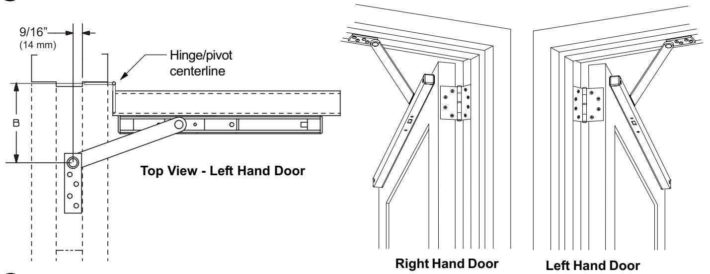
- Locate and mark "A" and "C" dimensions on door. Note that "A" dimension is measured from centerline of hinge as shown. For dead stop add 13/16" (21mm) to the "A" dimension from the chart. For more information about dead stop, see page 2 under "Notes on using chart".
- 8 Drill two 3/8" (10mm) diameter through holes per chart and dimensions shown below. Mounting holes should be prepared only after door and frame are installed.
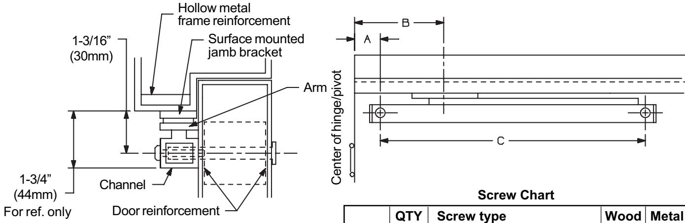
- 9 Install jamb bracket on the stop (see Screw Chart).
- Install the channel on the door (see Screw Chart) Shock spring should be located on hinge end of the door.
| QTY | Screw type | Wood | Metal | |
|---|---|---|---|---|
| Jamb | 4 | #14 x 1-1/2" FPHSMS | ~ | |
| Jailib | 4 | 1/4"-20 x 3/4" FPHMS | > | |
| Door | 2 | 1/4"-20 x 1-1/4" OPHMS | ~ | ~ |
| Dooi | 2 | 1/4"-20 x 2-1/2" Sex bolts | ~ | > |