Glynn Johnson 90 Series Function Conversions Installation Instructions 109044
Open the original PDF document
View PDF


829407-00
Function Conversions Installation Instructions
Hold-open to Stop Only
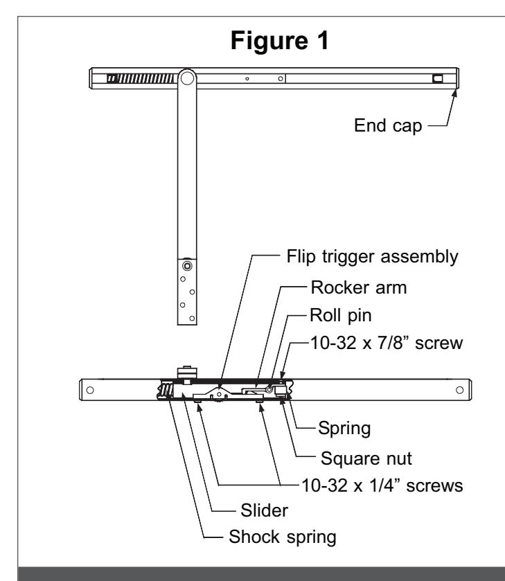
(Refer to Figure 1)
- 1. Remove the 2 screws on the bottom of the channel which hold the flip finger assembly in the channel.
- 2. With the slider away from the spring end of channel, remove the trigger assembly from the channel.
- L Note: When the trigger assembly is removed, the overhead will function as a stop only. Removing the holdopen components from the slider is not necessary for conversion.
Optional
- 3. Remove the overhead unit from door and frame.
- 4. Remove the end cap by knocking the slide against it.
- 5. Slide the arm assembly out of the channel.
- 6. Remove the screw at the end of the slider. The square nut and spring will drop out of the slider.
- 7. Remove the roll pin from the side of the slider. The rocker arm will drop out of the slider.
- 8. Slide the arm assembly into channel, with the short end of the slider toward the shock spring in channel.
- 9. Replace the end cap.
- 10.Reinstall the overhead unit.
Friction Hold-open to Stop Only
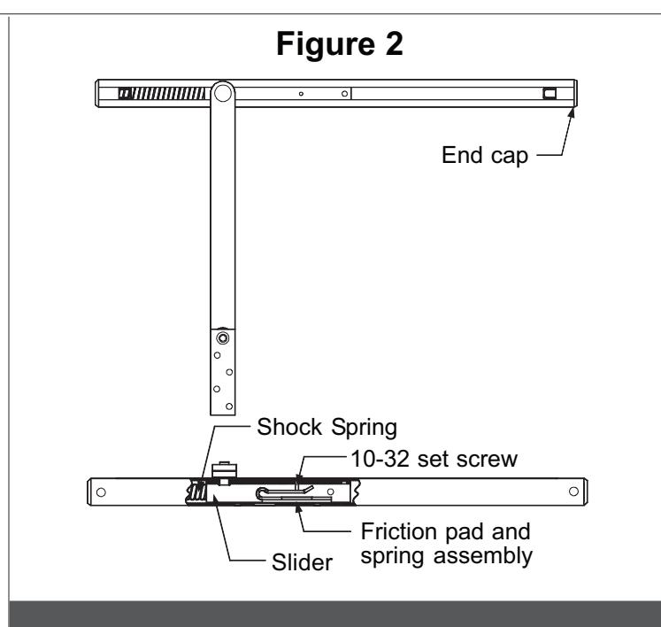
(Refer to Figure 2)
- 1. Remove the set screw from the top of the slider.
- L Note: When the set screw is removed from slider, the overhead will function as a stop only. Removing the friction components from the slider is not necessary for conversion.
Optional
- 2. Remove the overhead unit from door and frame.
- 3. Remove the end cap by knocking the slide against it.
- 4. Slide the arm assembly out of the channel. The friction pad and spring assembly will drop out of the slider.
- 5. Slide the arm assembly into channel, with the short end of the slider toward the shock spring in channel.
- 6. Replace the end cap.
- 7. Reinstall the overhead unit.
Stop Only to Hold-open
(Refer to Figure 1)
- 1. Remove the overhead unit from door and frame.
- 2. Remove the end cap by knocking the slide against it.
- 3. Slide the arm assembly out of the channel.
- 4. Place rocker arm inside slider as shown.
- 5. Install roll pin through slider and rocker arm.
- 6. Put screw through the top of the slider in the hole nearest the end of the slider.
- 7. Place spring over screw inside the slider.
- 8. Put square nut over screw and tighten about 4 turns.
- 9. Place the flip trigger assembly inside channel with the short end of the assembly toward the shock spring.
- 10.Secure the flip trigger assembly with 2 screws through the bottom of the channel.
- 11. Grease the rocker arm and the flip trigger with a graphite or white lithium grease, not supplied in kit.
- 12.Slide the arm assembly into channel, with the short end of the slider toward the shock spring in channel.
- 13.Replace the end cap.
- 14.Reinstall the overhead unit.
- 15.Adjust the hold-open tension as described in the installation instructions.
Friction Hold-open to Hold-open
(Refer to Figure 1 and 2)
- 1. Remove the overhead unit from door and frame.
- 2. Remove the end cap by knocking the slide against it.
- 3. Slide the arm assembly out of the channel. The friction pad and spring assembly will drop out of the slider.
- 4. Remove the set screw from the middle of the slider.
- 5. Place rocker arm in slider as shown.
- 6. Install roll pin through slider and rocker arm.
- 7. Put screw through the top of the slider in the hole nearest the end of the slider.
- 8. Place spring over screw inside the slider.
- 9. Put square nut over screw and tighten about 4 turns.
- 10.Place the flip trigger assembly inside channel with the short end of the assembly toward the shock spring.
- 11. Secure the flip trigger assembly with 2 screws through the bottom of the channel.
- 12.Grease the rocker arm and the flip trigger with a graphite or white lithium grease, not supplied in kit.
- 13.Slide the arm assembly into channel, with the short end of the slider toward the shock spring in channel.
- 14.Replace the end cap.
- 15.Reinstall the overhead unit.
- 16.Adjust the hold-open tension as described in the installation instructions.
Stop Only to Friction Hold-open
(Refer to Figure 2)
- 1. Remove the overhead unit from door and frame.
- 2. Remove the end cap by knocking the slide against it.
- 3. Slide the arm assembly out of the channel.
- 4. Remove any grease from inside channel.
- 5. Place friction pad and spring assembly into slider.
- 6. Slide the arm assembly back into the channel with the short end of the slider toward the shock spring end of the channel.
- 7. Put set screw in top of slider.
- 8. Replace the end cap.
- 9. Reinstall the overhead unit.
- 10.Adjust the friction hold-open tension as described in the installation instructions.
Hold-open to Friction Hold-open
(Refer to Figure 1 and 2)
- 1. Remove the overhead unit from door and frame.
- 2. Remove the end cap by knocking the slide against it.
- 3. Slide the arm assembly out of the channel.
- 4. Remove the 2 screws on bottom of channel which hold the flip trigger assembly in the channel.
- 5. Remove the trigger assembly from channel.
- 6. Remove any grease from inside channel.
- 7. Remove the screw from the end of the slider. The square nut and spring will drop out of the slider.
- 8. Remove the roll pin from the side of the slider. The rocker arm will drop out of the slider.
- 9. Place friction pad and spring assembly into slider.
- 10.Slide the arm assembly back into the channel with the short end of the slider toward the shock spring end of the channel.
- 11. Put set screw in top of slider.
- 12.Replace the end cap.
- 13.Reinstall the overhead unit.
- 14.Adjust the friction hold-open tension as described in the installation instructions.