First Choice Building Products Model MEL3000 Retrofit Installation Instructions
Open the original PDF document
View PDF

Model MEL3000 Retrofit Instructions
MEL 3000 Kit Contents:
- New activating bracket
- Motor-Drive assembly
- Notched Pin & E-Clip
- Narrow Rubber Bumper
- Wire harness
- Hinge stile mounting bracket w/ wire access hole
Step 1 – Preparation
A. Electrical power
1.A.1 - Install a First Choice power supply per the instructions provided. Power Supply MUST be class II rated in order to meet UL listing requirements.
1.A.2 - Run wiring from power supply to the door(s).
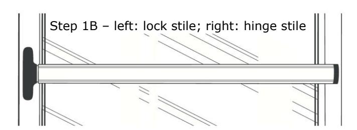
B. Remove pushbar device from the door.
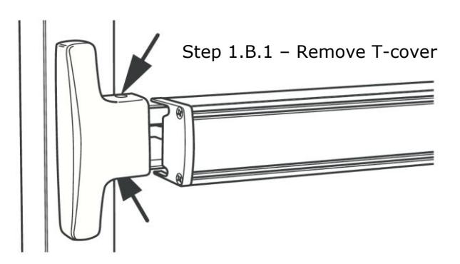
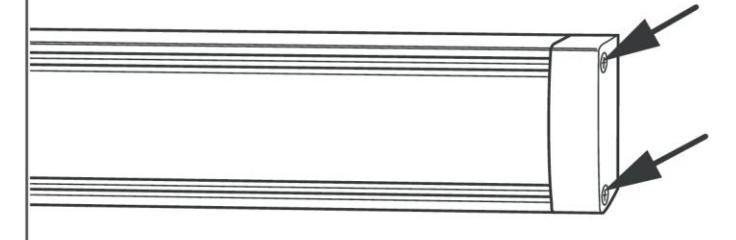
1.B.1 - Remove T-cover on lock stile end.
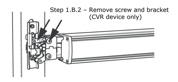
1.B.2 - Remove top axle screw & pinion support bracket.
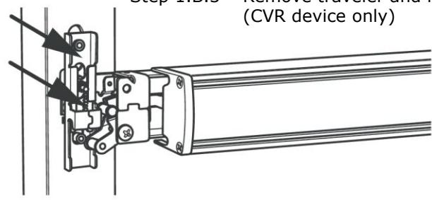
1.B.3 - Remove geared traveler and retractor.
1.B.4 - Remove hinge stile end cap.
1.B.5 - Loosen the hinge stile mounting screws.
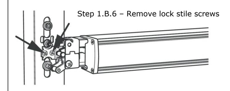
1.B.6 - Remove lock stile mounting screws.
Step 1.B.3 – Remove traveler and retractor (CVR device only)
Step 1.B.4 – Remove hinge stile end cap
Step 1.B.5 – Loosen bracket screws. Do not remove.
Step 1 - Preparation (continued)
- C. Remove pushbar.
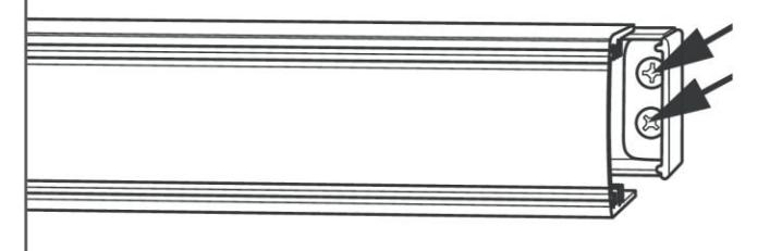
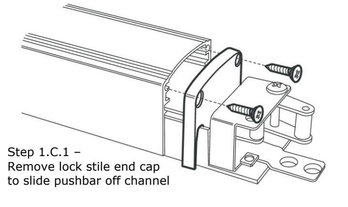
- 1.C.1 - Remove lock stile end cap.
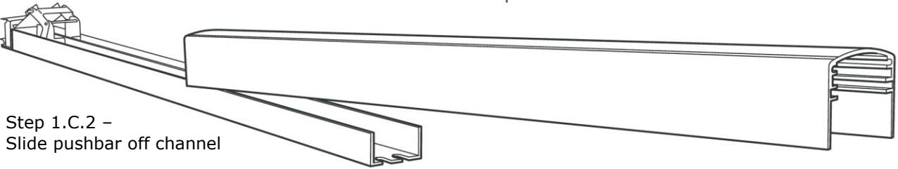
- 1.C.2 - Slide push bar toward hinge stile.
- 1.C.3 - Remove dogging assembly from the channel by removing two (2) screws on channel.
- Discard old dogging assembly but keep axle pins.
Step 2.3 – Trim connecting rod
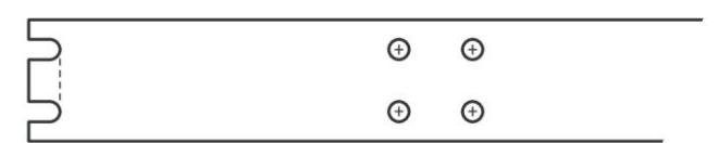
Step 3.1 – Provide opening for wiring
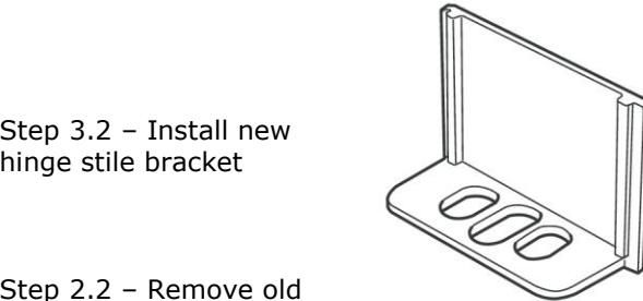
Step 2.2 – Remove old

- 2.1 - Remove rear activating (dogging) bracket by removing 2 screws on back of channel.
- 2.2 - Remove activating bracket axle pin to disconnect connecting rod. Remove other parts as necessary to access connecting rod.
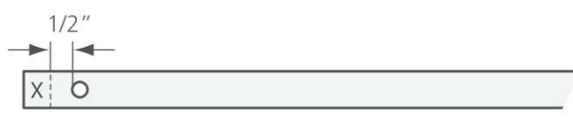
- 2.3 - Trim connecting rod as shown, allowing 1/2" from axle hole to remain.
Step 3 - Provide wiring access
- 3.1 - Cut notch or drill hole in back of channel to permit routing of connector that is on end of wire harness.
- 3.2 - Remove and replace hinge stile mounting bracket on door with new bracket provided. Do not tighten screws. Discard old bracket.

- 4.1 - Assemble new rear activating bracket to shortened connecting rod with notched axle pin and narrow bumper.
- 4.2 - Install E-clip onto notch of axle pin (AFTER assembled with connecting rod), next to bumper, to restrict bumper from moving along axle.
- 4.3 - Apply grease to bumper and notched axle pin to provide lubrication for movement inside bracket. Do not yet secure bracket to channel.
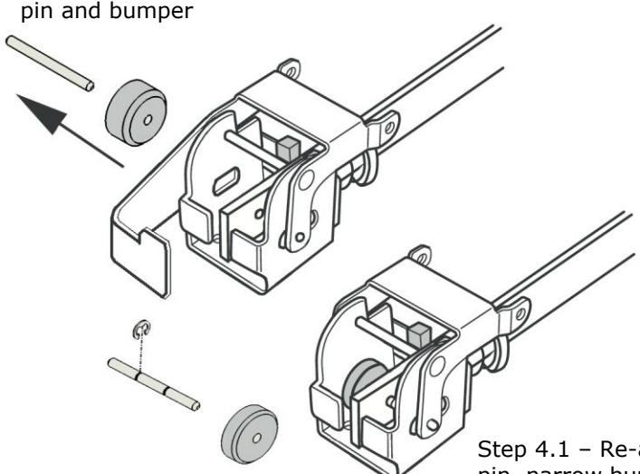
Step 4.1 – Re-assemble with notched pin, narrow bumper, & E-clip
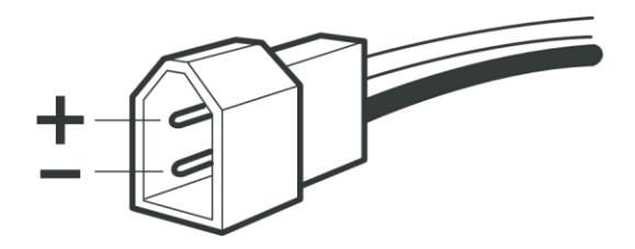
Step 6.2 – Plug polarity

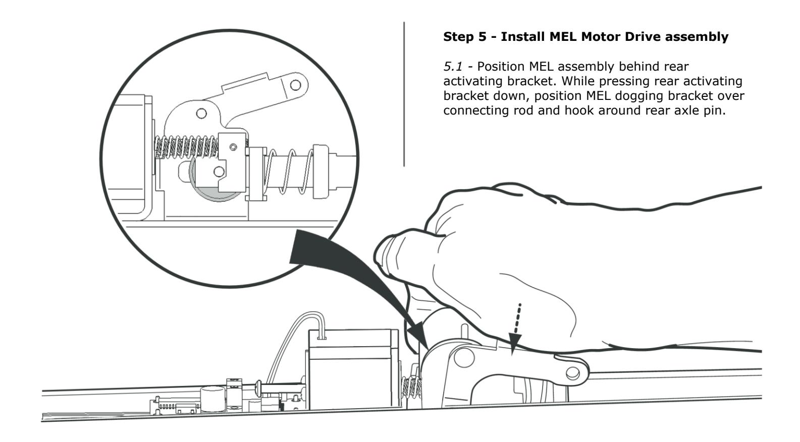
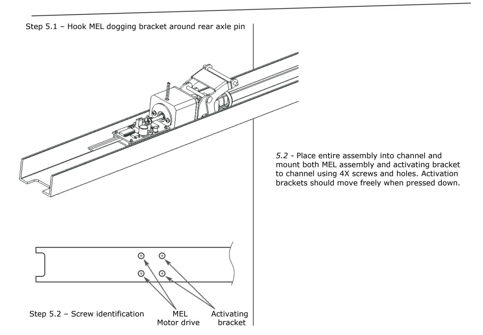
Step 6 - Re-assemble and install
- 6.1 - Mount channel assembly to door with channel underneath new hinge stile bracket. Attach device to lock stile and tighten screws, then tighten hinge stile bracket mounting screws.
- 6.2 - Make wiring power connections and test for proper Motor operation. Power Supply MUST be class II rated in order to meet UL listing requirements.
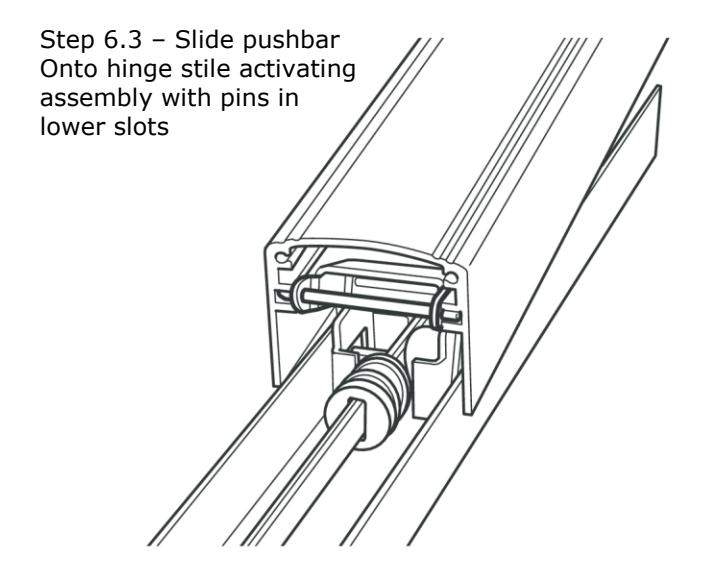
- 6.3 - Re-assemble pushbar onto channel and activating assemblies by sliding onto pins of activating brackets – pins will only fit in lower pushbar slots.
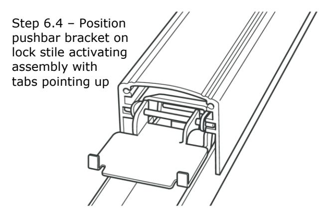
- 6.4 - Make sure the pushbar bracket stop tabs are installed with tabs turned up, away from the channel.
- 6.5 - Reinstall end caps.