First Choice Building Products Model EL3000 Retrofit Installation Instructions
Open the original PDF document
View PDF

Model EL3000 Retrofit Instructions
EL3000 Kit Contents:
- New activating bracket to replace rear (dogging) bracket
- Solenoid assembly with Coil Commander
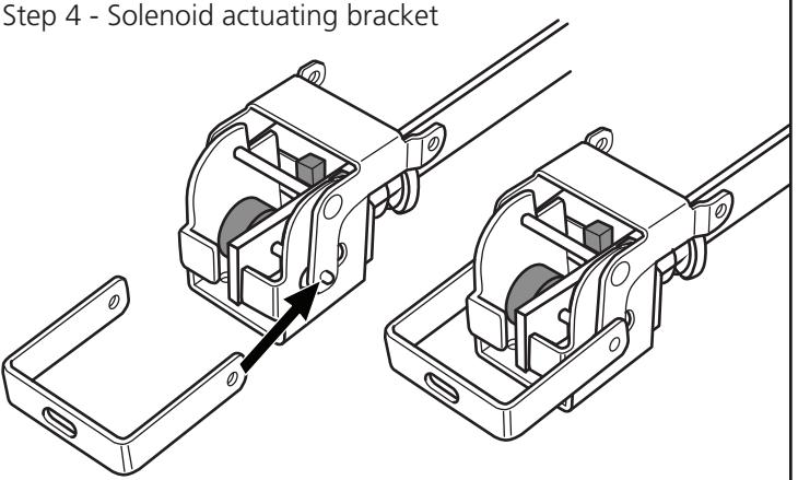
- Solenoid actuating bracket
- Wire harness
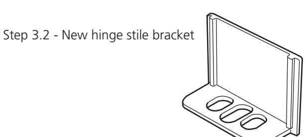
- Hinge stile mounting bracket with wire access hole
Step 1 - Preparation
A. Electrical power
- 1.A.1 Install a First Choice power supply per the instructions provided.
- 1.A.2 Run wiring from power supply to the door(s).
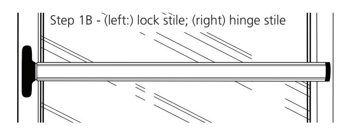
- B. Remove pushbar device from the door.
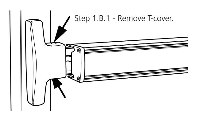
- 1.B.1 Remove T-cover on lock stile end.
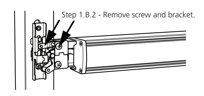
- 1.B.2 Remove top axle screw and pinion support bracket.
- 1.B.3 Remove geared traveler and retractor.
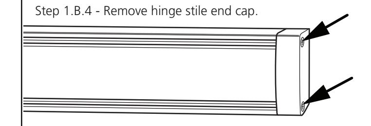
- 1.B.4 Remove hinge stile end cap.
- 1.B.5 Loosen the hinge stile mounting screws.
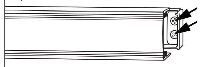
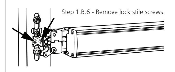
- 1.B.6 Remove lock stile mounting screws.


Step 1 - Preparation (continued)
- C. Remove pushbar.
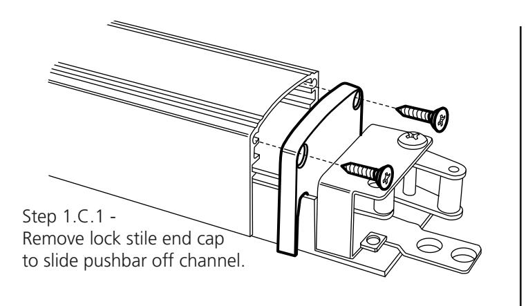
- 1.C.1 Remove lock stile end cap.
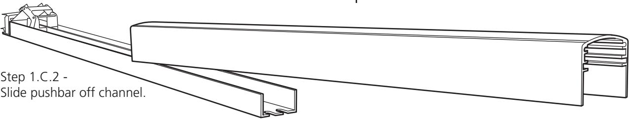
- 1.C.2 Slide push bar toward hinge stile.
- 1.C.3 Remove dogging assembly from the channel with two (2) screws on channel. Discard old dogging assembly but keep axle pins.
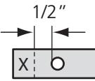
Step 2.3 - Trim connecting rod.
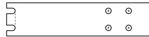
Step 3.1 - Provide opening for wiring.
Step 2 - Shorten the connecting rod
- 2.1 Remove rear activating (dogging) bracket with 2 screws on back of channel.
- 2.2 Remove activating bracket axle pin to disconnect connecting rod. Remove other parts as necessary to access connecting rod.
- 2.3 Trim connecting rod as shown, allowing 1/2" from axle hole to remain.
Step 3 - Provide wiring access
- 3.1 Cut notch or drill hole in back of channel to permit routing of connnector that is on end of wire harness.
- 3.2 Remove and replace hinge stile mounting bracket on door with new bracket provided. Do not tighten screws. Discard old bracket.
Step 4 - Activating hardware assembly
- 4.1 Assemble new rear activating bracket to shortened connecting rod with axle pin.
- 4.2 Place the solenoid actuating bracket onto ends of axle pin with a gentle spread of the actuating bracket ends.
- 4.3 Apply grease to outer surfaces of solenoid bracket to provide lubrication for movement in the channel.
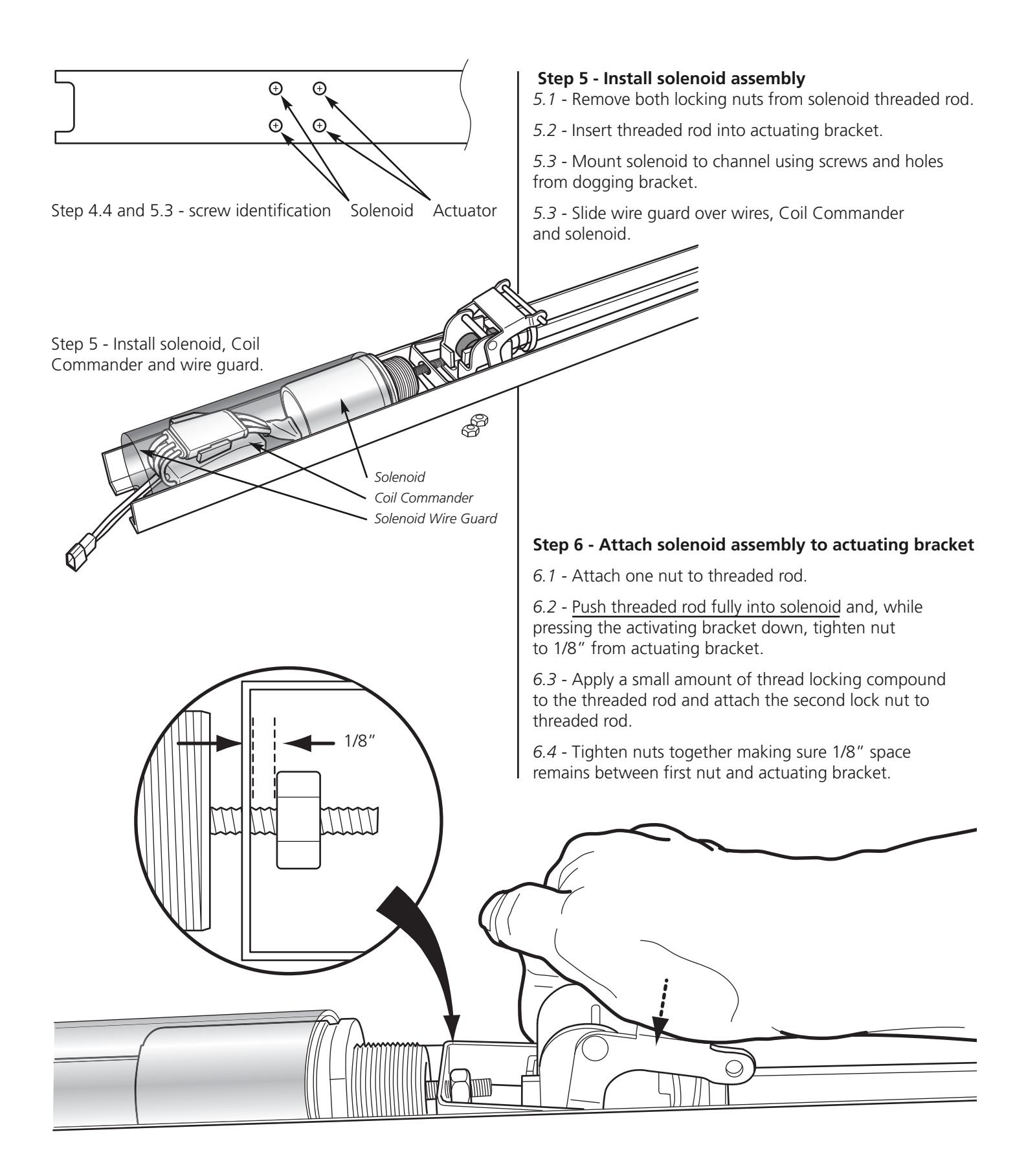
- 4.4 Mount rear activating bracket assembly into channel.
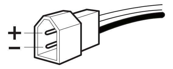
Step 7.2 - Plug polarity
Step 7.3.2 - pushbar bracket installs on lock stile activating assembly with tabs pointing up.

Phone: (800) 793-4544 Fax: (800) 867-5016
www.firstchoicebuildingproducts.com
Step 7 - Re-assemble and install
- 7.1 Mount channel assembly to door with channel underneath new hinge stile bracket. Attach device to lock stile and tighten screws, then tighten hinge stile bracket mounting screws.
- 7.2 Make wiring power connections and test for proper solenoid operation.
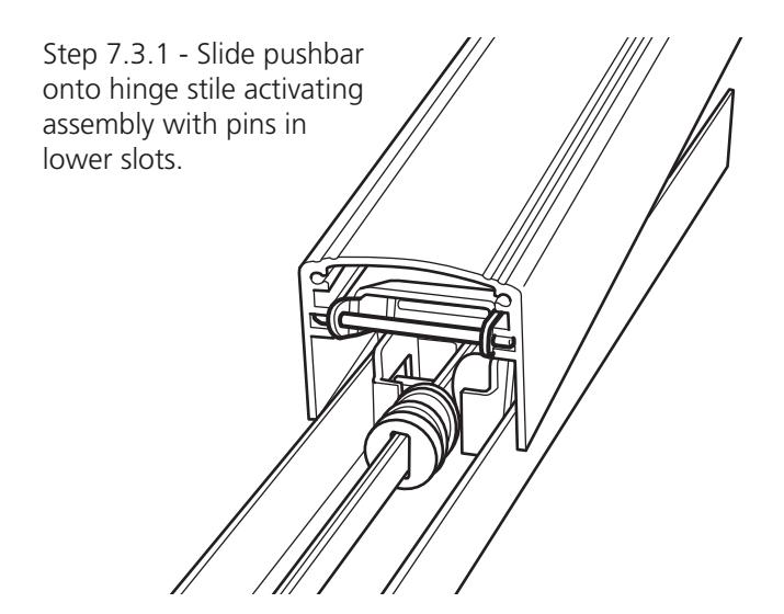
- 7.3.1 Re-assemble pushbar onto channel and activating assemblies by sliding onto pins of activating brackets – pins will only fit in lower pushbar slots.
- 7.3.2 Make sure the pushbar bracket stop tabs are installed with tabs turned up, away from the channel.
- 7.4 Reinstall end caps.