First Choice Building Products Mechanical & Electrical Control Levers Installation Instructions
Open the original PDF document
View PDF
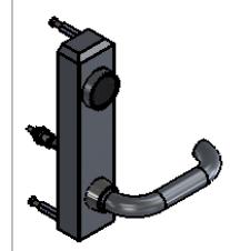
First Choice Building Products INSTALLATION INSTRUCTIONS
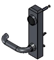
Mechanical & Electrical Control Levers for use with Rim & CVR Exit Devices
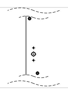
(A) Door Preparation
Previously Installed Exit Device
- 1) Remove the device from the door
- 2) Using the paper template provided, mark the interior of the holes as marked.
- 3) Remove rim cylinder or any other hardware no longer needed.
New Exit Device
1) Prep the door for the exit device as per the separate instructions and template. Use the template provided with the device to prep the exterior.
(B) Cylinder Installation
Place cylinder in lever trim prior to installing lever trim onto door. 1-1/8" to 1-1/4" Mortise Cylinders required.
(C) Wiring Connection EL models only
Electric Control Lever Trim Only
Wires should come through the door and under chassis cover and be fed into touchbar. Connect wires. Transfer wires from the exit device through intermediate hinge, door cord or surface loop to access control system.
- *Solenoid in the Exit Device Trim requires 24vDC and has a draw of 300mA
- * trim will work mechanically until hooked up to power source.
Again: Be careful wires are not pinched or cut as they are worked through door!
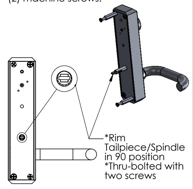
(D) Lever & Device Installation
1) Install exit device & lever trim making sure wiring + connector (if Electric) does not get cut or pinched.
2) Fasten the trim to the door with two (2) machine screws.
FIRST CHOICE
BUILDING PRODUCTS
REVISED: 06.21.2012