First Choice Building Products MEL Exit Device-1 Pair-2 Active PSMEL2000 Wiring Diagram
Open the original PDF document
View PDF

NOTES:
- 1) Verify that each component requiring or supplying power has been configured for proper system voltage before applying power.
- 2) All wires to be 18 awg 100' max unless otherwise noted on drawing. Refer to manufacturers instructions for proper wire gauge on any power supply, electric device or electrified lock hardware. Manufacturers requirements take precedence.
- 3) All line voltage power to be I/A/W local electrical code.
- 4) All low voltage wires to be stranded copper unless superseded by local electrical code or electric device manufacturer.
- 5) It is considered good electrical practice to run spare wires at any location that may be difficult to access after construction.
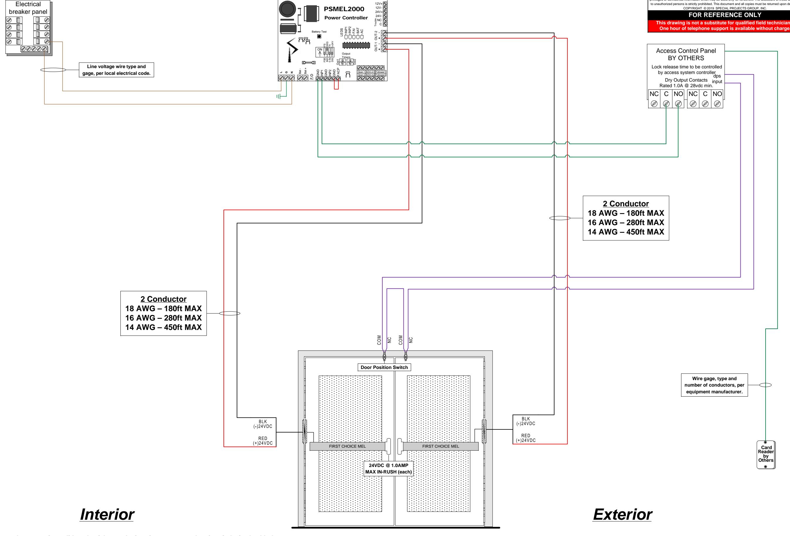
Electrical Circuit Legend Red = (+)VDC Power Black = (-) VDC Power Green = Signaling Blue = Activation Violet = Monitoring/Supervisory Brown = AC High Voltage
Function Statement:
<u>From exterior - locked condition:</u> Access by presenting valid credential at reader interface to retract electric exit device latchbolts. <u>From exterior - unlocked condition:</u> Doors to remain locked unless electric exit device held retracted by access control system.
<u>From interior - locked condition:</u> Free egress at all times by means of exit device. <u>From interior - unlocked condition:</u> Free egress at all times by means of exit device.
General: Fail-secure electric latch retraction exit devices to remain locked during utility power-loss event.
| Title: Pair MEL Exit Device PS-MEL-2000.vsd | Project: Example | ||||||||
|---|---|---|---|---|---|---|---|---|---|
| HWSET: Example | Door: EXT-1 | ||||||||
| Date: | 5/17/2019 | Date Printed: | 5/16/2019 | Last Revised: 5/16/2019 | 11:54:30 AM | ||||
| Drawn By: Eric Norton | For: | Special Pro | ects Group | S0: | n/a | Pg: 1 OF 1 | |||