First Choice Building Products 3600 Series Concealed Vertical Rod Exit Devices Installation Manual
Open the original PDF document
View PDF

Series 3600 Concealed Vertical Rod Exit Devices
(630) 350-2770 WWW.firstchoicebuildingproducts.com
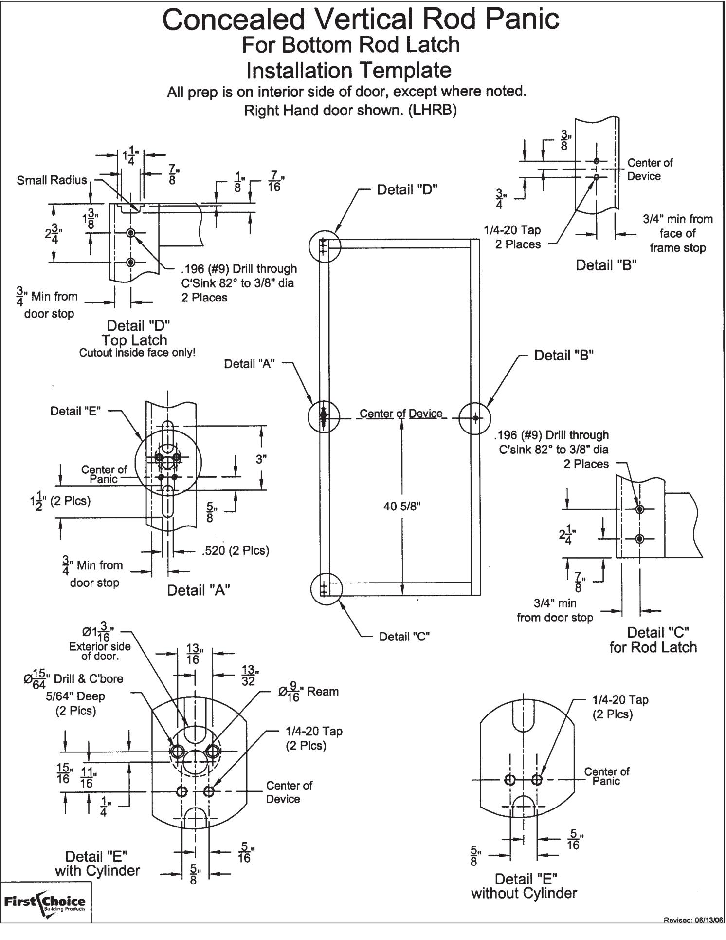
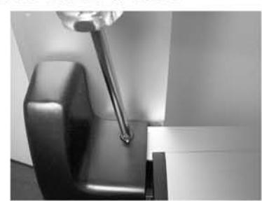
TO INSTALL VERTICAL ROD LATCHES
(Rods are factory preset for door height of 83 3/16" and a cylinder location of 41 5/16" - see page 4 for additional details.)
Install top latch mechanism using 2 ea. #10-32x1/4" screws.
Affix bent end of rod to door using rod bushing with "E" ring.
INSTALL BOTTOM ROD ASSEMBLY IN THE SAME MANNER AS ABOVE.
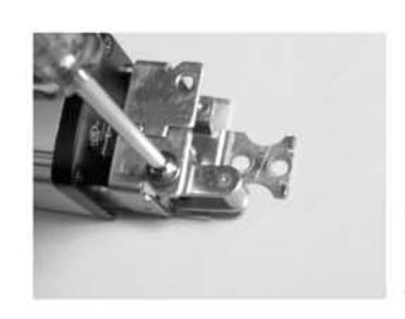
TO INSTALL ACTIVATING DEVICE
Prepare door as per template on page 8.
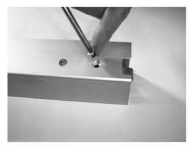
Install the hinge stile mounting bracket with 2 ea. 1/4-20 x 1/2" pan head screws leaving space to capture the base of the device (see next step).
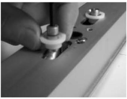
TO INSTALL ACTIVATING DEVICE CONTINUED
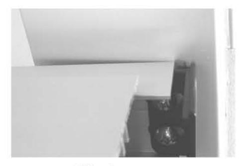
Fig. A
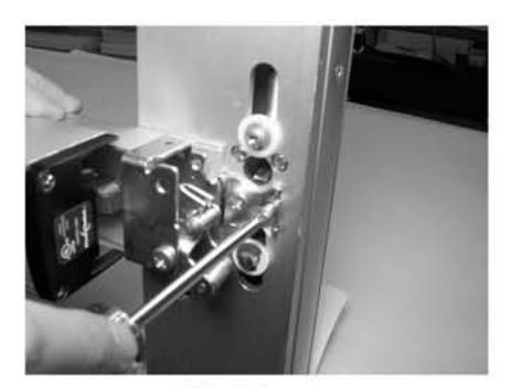
Fig. B
Slip the device base under the mounting bracket (Fig. A) and attach device to the lock stile with 2 ea. \( \frac{1}{4}\)-20x1/2" flat head screws (Fig. B). Tighten all four \( \frac{1}{4}\)-20 screws to secure the device.
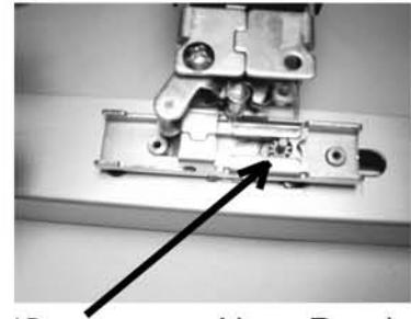
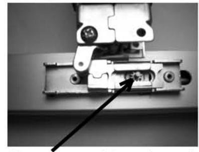
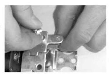
With the traveler positioned as shown, locate it over the rod ends.
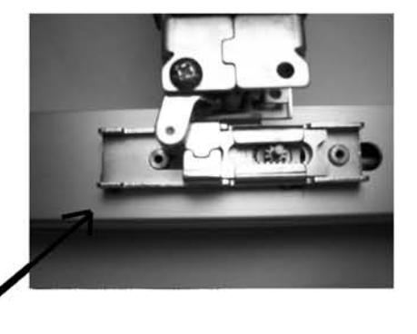
TRAVELER
CHECK ROD OPERATION
After dogging the device -
When tripped by hand, the top latch should swing freely through it's travel.
If not completely free, lengthen the top rod by loosening the jamb nut and rotating the rod counter-clockwise.
The bottom latch should protrude 1/16" or less beyond the bottom of the door.
To shorten the bottom rod, loosen the jamb nut and rotate the rod clockwise.
FCBP Document Control No. 30M36
CHECK ROD OPERATION CONTINUED
After un-dogging the device -
The top latch should not trip when operated by hand. If hand pressure can trip the latch, shorten the rod by loosening the jamb nut and rotating the rod clock-wise.
NOTE-The bottom rod may require adjustment to accommodate changes to the top rod.
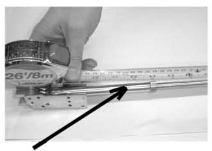
34 1/4"
The top rod is factory set to 34-1/4" measured from the bent end to the latch side of the jamb nut.
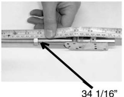
The bottom rod is factory set to 34-1/16" measured from the bent end to the latch side of jamb of jamb nut.
FOR DEVICES WITH KEY CYLINDER
Prepare doors with cylinder holes as per template on page 8.
Trim the cylinder tail piece so that it is slightly below the door face after mounting.
Install key cylinder using mounting screws supplied with the cylinder. (The screws may need to be shortened.)
TRIMMED TAILPIECE.
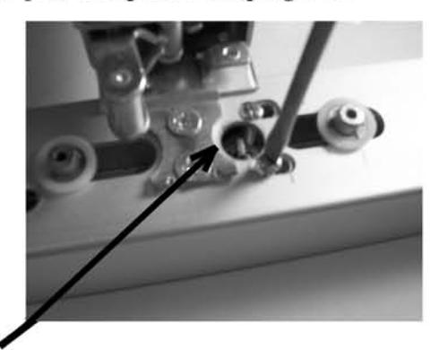
Install the pinion gear and bushing with the indicator edge up. This will align the slots to match the tail piece.
ALIGN FLAT SIDE TO TOP OF DOOR.
FOR DEVICES WITH KEY CYLINDER CONTINUED
With the retractor installed into the traveler, position the retractor over the pinion gear and position the traveler over the rod ends. (Temporarily removing the crank roller may facilitate this procedure.)
Set retractor at the top of rotation for cylinder <u>Hold Back</u> function, or set it midway along the rotation for <u>Night Latch</u> function.
Proceed to next step to secure pinion gear.
(SETTING FOR HOLD BACK)
(SETTING FOR NIGHT LATCH)
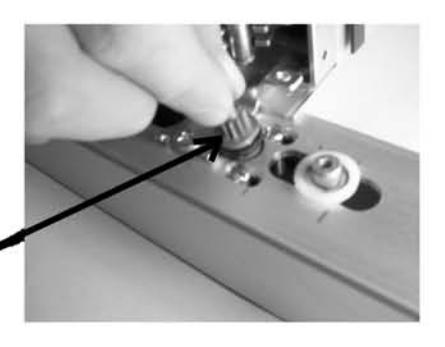
TO SECURE THE PINION GEAR:
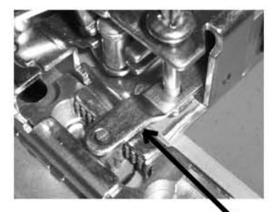
Install the pinion retainer over the pinion and onto the crank bracket using an axle screw.
PINION RETAINER
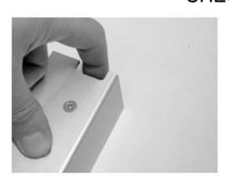
COMPLETING THE INSTALLATION:
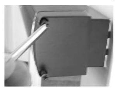
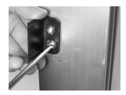
Mount the inactive side end cap using 2 ea. #8-32 x 1 ½" screws.
Install active side cover using two each #10-32 x 3/8" screws.
TO CHANGE HAND OF DEVICE:
Remove the crank roller assembly axle screw from crank bracket.
Flip the crank roller assembly over and locate on the opposite side of the crank bracket. Reattach with the axle screw.
|
Reference
Number |
Description | Part Number |
Quantity
Per Device |
|---|---|---|---|
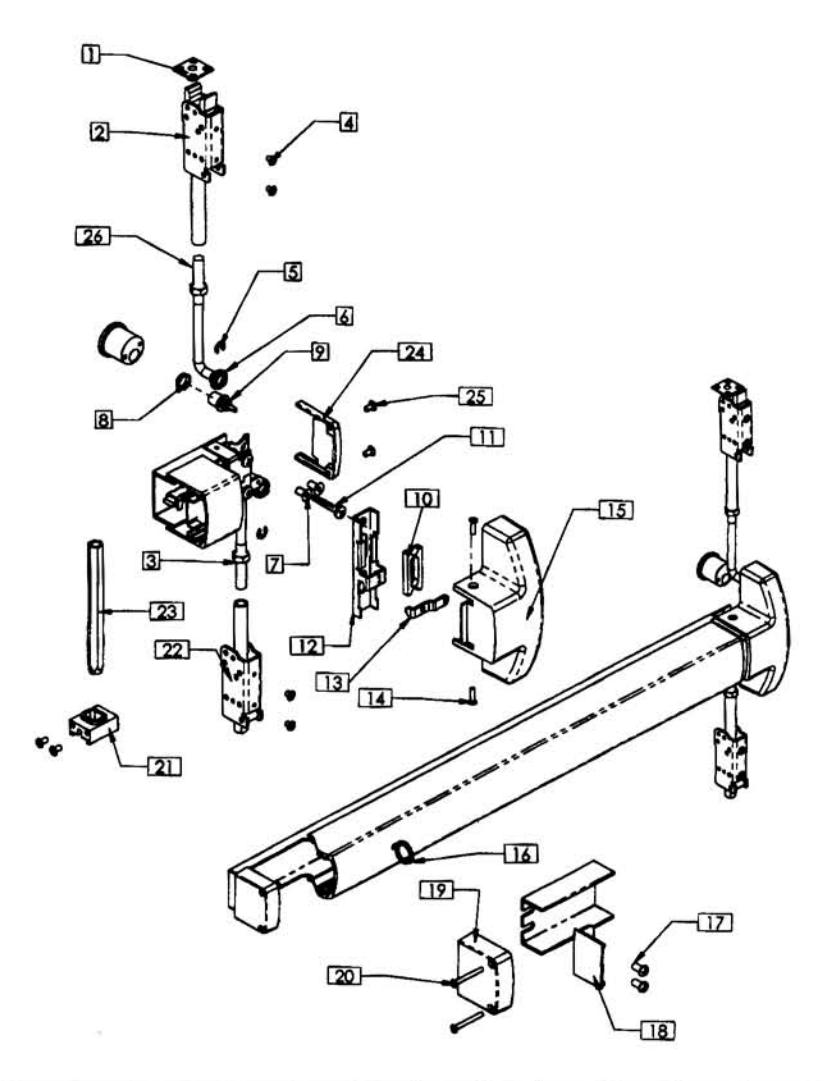
| 1 | Top Strike Kit - SS | 9038 | 1 |
| Consists of: | 3000 | 1. | |
| Top Strike (1 ea.) | 16001238 | ||
| Strike Shim (3 ea.) | 16001230 | ||
| 2 | Top Latch Assembly | 42 | 1 |
| 3 | Jamb Nut | 806 | 2 |
| 4 | Latch Housing Screw | 811-CL, 811-BR | 4 |
| 5 | Retaining E-Ring | 809 | 2 |
| 6 | Rod Bushing | 810 | 2 |
| 7 | Lock Stile Mounting Screw | 816 | 2 |
| 8 | Cylinder Bushing | 16001004 | 1 |
| 9 | Pinion | 16001007 | 1 |
| 10 | Retractor | 16001003 | 1 |
| 11 | Axle Screw | 3 | 1 |
| 12 | Traveler | 16001098 | 1 |
| 13 | Pinion Support Bracket | 821 | 1 |
| 14 | Cover Screw | 804 | 2 |
| 15 | Center Case Cover | 40 | 1 |
| 16 | Dogging Key | 819 | 1 |
| 17 | Hinge Stile Mounting Screw | 801 | 2 |
| 18 | Channel End Cap | 33 | 1 |
| 19 | Hinge Stile Push Bar End Cap | 30 | 1 |
| 20 | End Cap Mounting Screw | 802 | 2 |
| 21 | Weighted Latch Guide w/ Screws | 77 | 1 |
| 22 | Bottom Latch Assy - Spring | 45 | 1 |
| 23 | Bottom Latch Assy - Weighted | 76 | 1 |
| 24 | Lock Stile End Cap | 50 | 1 |
| 25 | LS End Cap Mounting Screw | 838 | 2 |
| 26 | Vertical Rod w/ locking nut | 16001015 | 2 |
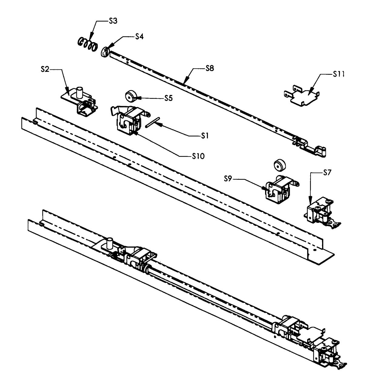
| Reference | Quantity | ||
|---|---|---|---|
| Number | Description | Part Number | Per Device |
| S1 | Axle Pins | 14 | 2 |
| S2 | Dogging Assy. | 71 | 1 |
| S3 | Spring | 23 | 1 |
| S4 | Spring Cap | 24 | 1 |
| S5 | Roller Stop | 17 | 2 |
| S7 | Crank Bracket Assy. | 9040 | 1 |
| S8 | Activating Connecting Rod | 21 | 1 |
| S9 | Lock Stile Activating Bracket | 9034 | 1 |
| S10 | Hinge Stile Activating Bracket | 70 | 1 |
| S11 | Push Bar Bracket | 15 | . |
ADDITIONAL ITEMS NOT REFERENCED -
| Bottom Rod & Latch Assy - Spring | 9045 | 1 |
|---|---|---|
| Bottom Rod & Latch Assy - Weighted | 9076 | 1 |
| Pullman Top Latch For Electric Strike | P42 | 1 |
| Top Rod & Latch Assy. | 9042 | 1 |
| Push Bar Assy - x Long - Clear | 360036-CL | 1 |
| Push Bar Assy - x Long - Bronze | 360036-BR | 1 |