First Choice Building Products 3100 Series Mid Rail Vertical Rod Exit Devices Installation Manual
Open the original PDF document
View PDF

Series 3100 Mid Rail Vertical Rod Exit Devices
Phone: (800) 793-4544
www.firstchoicebuildingproducts.com
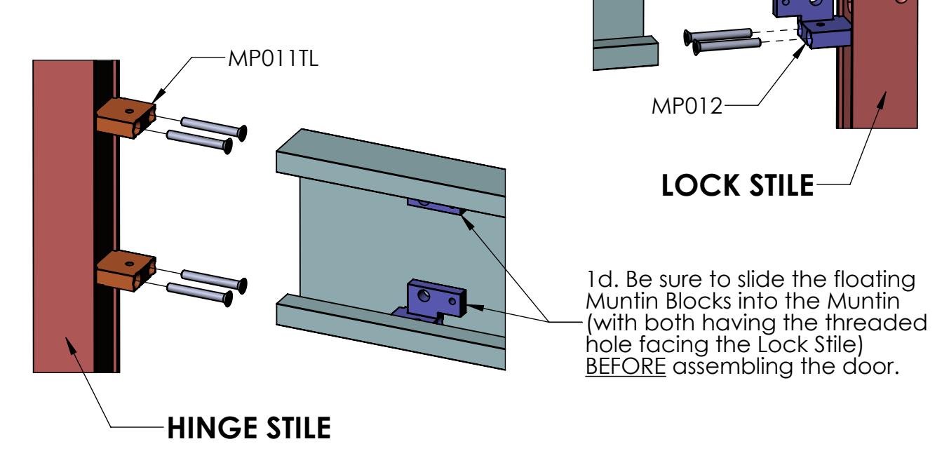
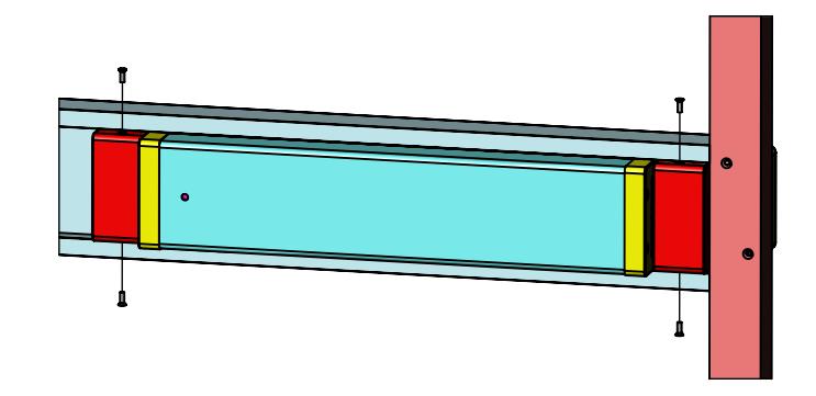
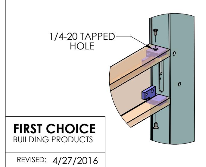
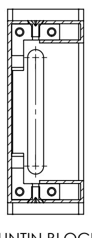
1b. Mount MP011 and MP012 Muntin Blocks onto Lock Stile using 2X 1/4-20 x 2" FHCS screws.
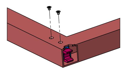
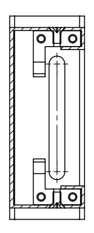
1c. Mount 2X MP011TL Muntin Blocks onto Hinge Stile using 2X 1/4-20 x 2" FHCS screws.
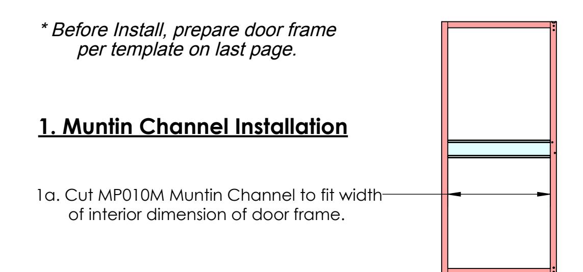
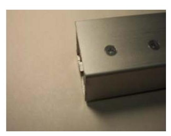
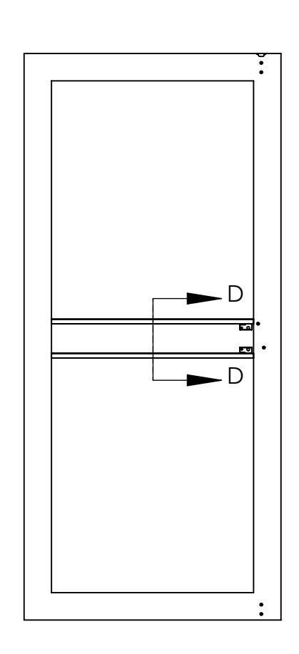
1e. With the door frame loose/unassembled, position the MP010M Muntin Channel between the Stiles and slide it over the Muntin blocks . Finish the assembly of the door frame.
MP011-
Set screws are provided to further tighten Muntin Channel to the Mounting Blocks, if needed. Use caution, do not over-tighten set screws.
FIRST CHOICE BUILDING PRODUCTS
F F 5 9/16" REF. (THIS AREA MUST BE CLEANED UP PRIOR TO MID-PANEL INSTALLATION) 5/16" 5/16" VIEW F-F MP023 DOOR FRAME MACHINING NOTE REVISED: FIRST CHOICE BUILDING PRODUCTS 4/25/2016
2. Vertical Rod Latches Installation
(Rods are factory preset for door height of 83 3/16" and a cylinder location of 41 5/16")
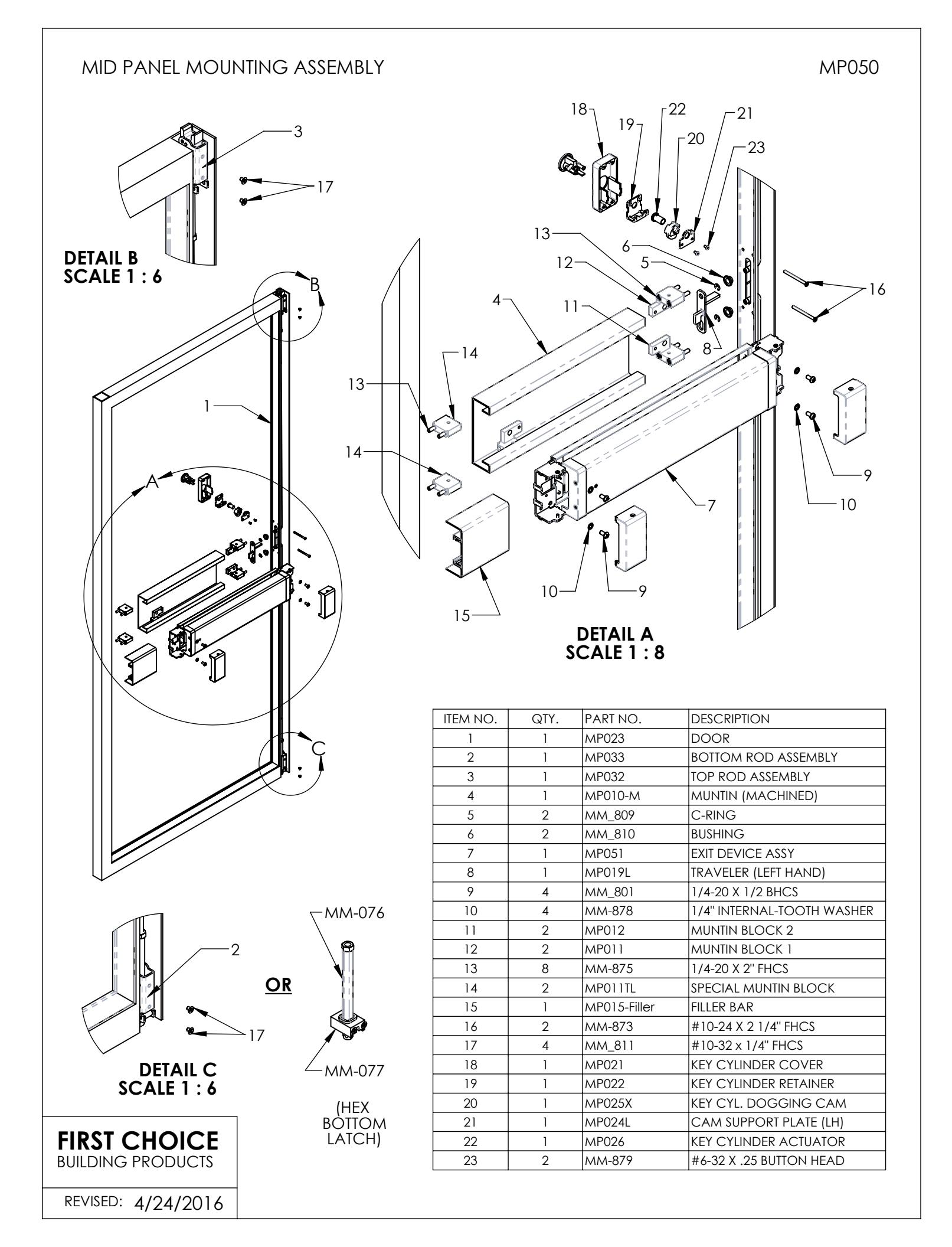
2a. Insert MP032 Top Latch Assembly into the Lock Stile, locating bent end of the rod thru slot in Stile. Secure using 2X #10-32 x 1/4" FHCS screws.
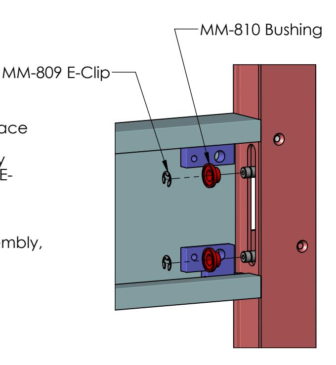
2b. With bent-end thru the slot, place MM-810 Plastic Bushing over rod (larger-diameter side facing away from Lock Stile) and affix MM-809 E-Clip to groove in rod.
2c. Install MP033 Bottom Rod Assembly, repeating the steps from above.
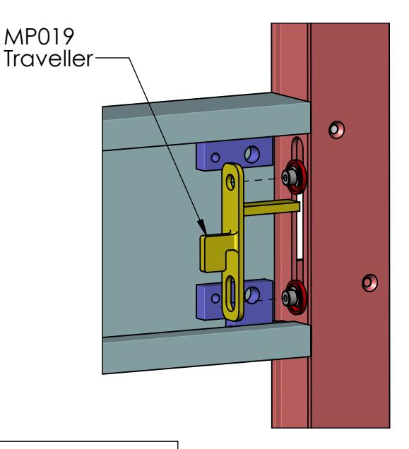
2d. Install appropriately handed MP019 Traveler over ends of vertical rods, with the slotted hole mating with Bottom Latch Rod.
Test the Traveller to make sure Bushings ride smoothly in the Slot, and that when lifted, the Top Latch trips.
FIRST CHOICE BUILDING PRODUCTS
3. Activating Device Installation
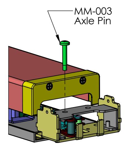
3a. Set the proper handing for the exit device. To change handing, remove MM-003 Axle Pin and flip Crank Sub-Assembly to opposite side.
LEFT HAND DOOR
RIGHT HAND DOOR
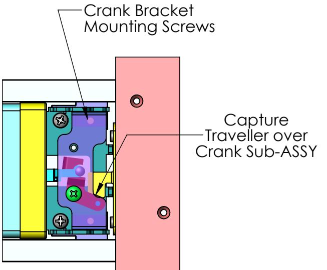
3b. Insert the MP051 Activating Assembly, active side first, into Muntin Channel. Be sure to capture the Traveler over the Crank Sub-Assembly.
The Crank Bracket Mounting Screws should seat into clearance holes in Muntin Blocks, on the active side, to assure proper spacing.
3c. Attach the Activating Assembly to the Muntin Blocks using 4X 1/4-20 x 1/2" BHCS screws and 4X Lock Washers.
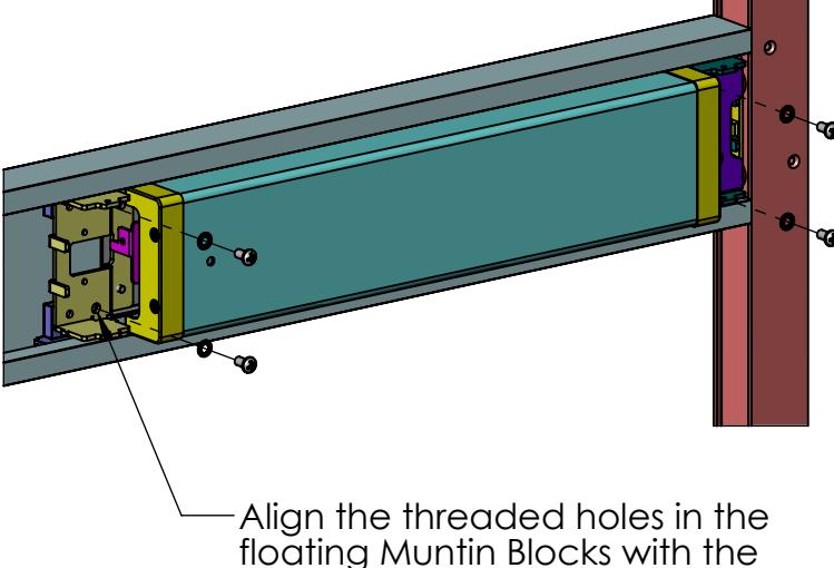
large holes in the bracket.
FIRST CHOICE BUILDING PRODUCTS
Activating Device Installation (Cont'd.)
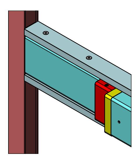
3d. Install MP018 End Caps onto Activating Assembly, each with 2X 8-32 x 1/2" FHCS screws. Be sure to orient End Caps correctly so that the side with the thicker wall faces away from push bar.
Note: The End Cap with the UL label should be placed on the Hinge-Stile side.
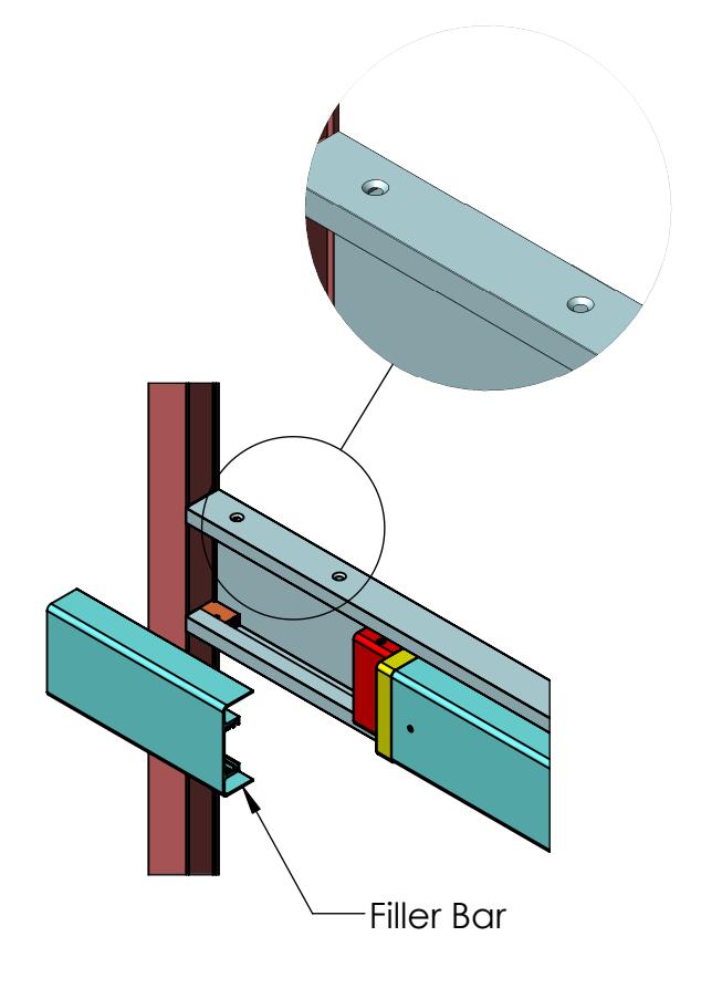
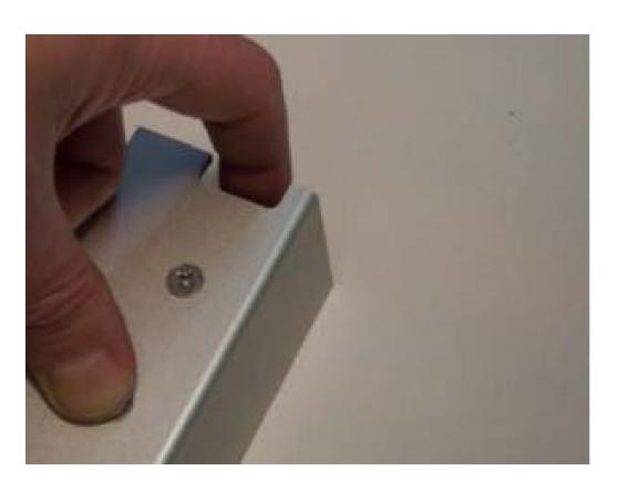
3e. Measure the distance between Hinge Stile and End Cap, and cut Filler Bar to fit into the space.
3f. Drill and C'Sink 4 holes into top and bottom of Muntin Channel. Use 4X Self-Drilling/Self-Tapping screws to secure Filler Bar in place.
FIRST CHOICE BUILDING PRODUCTS
4. Installing Devices With KEY CYLINDER
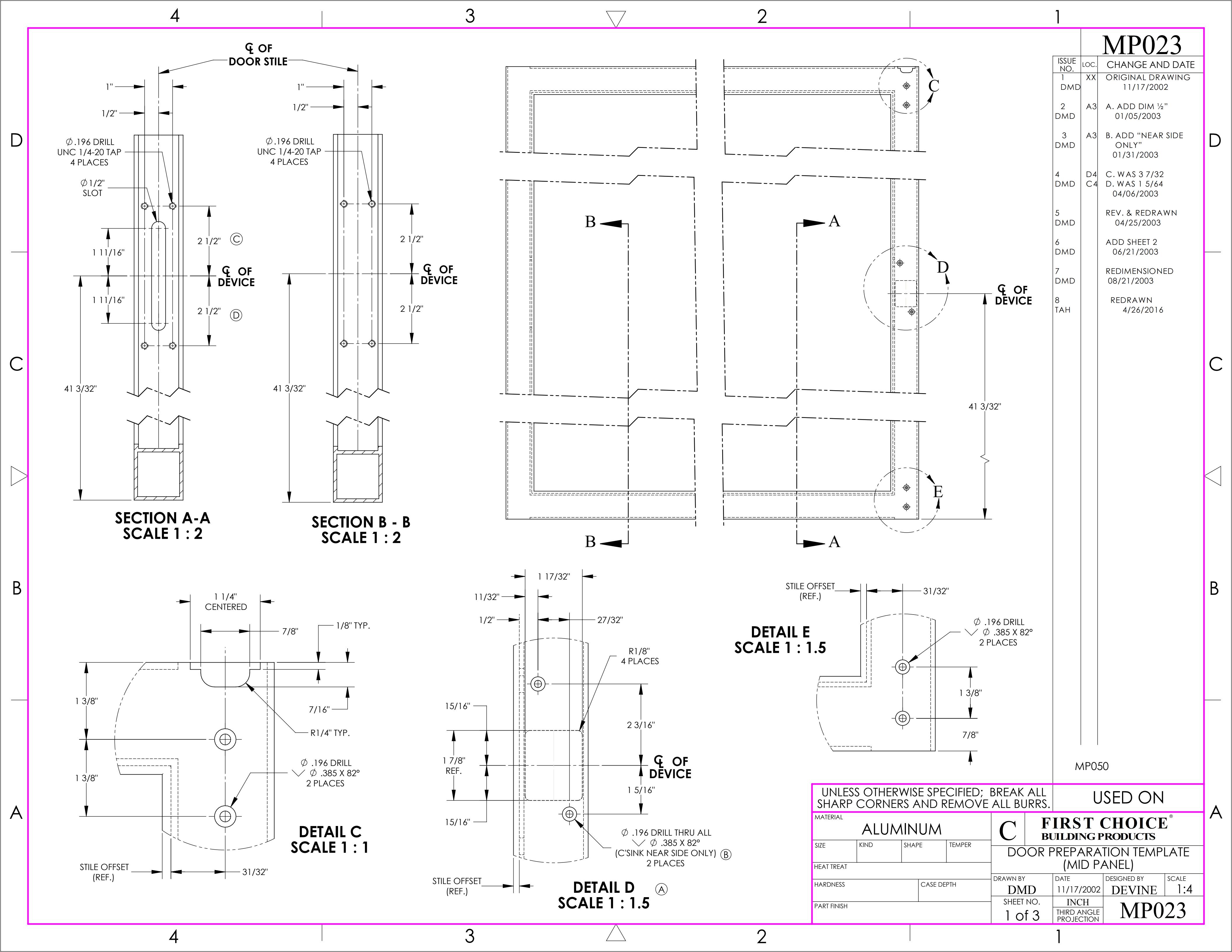
Prepare doors with cylinder holes per template on last page.
4a. Install key cylinder into the MP021 Cylinder Mounting Assembly using mounting screws supplied with the cylinder. (The screws may need to be shortened.)
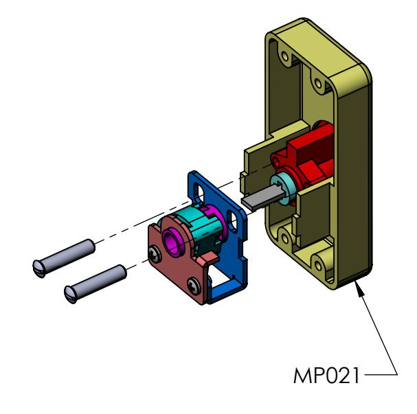
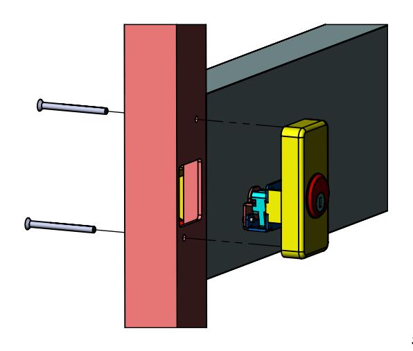
4b. Mount MP021 Cylinder Assembly to Lock Stile using 2x 10-24 x 2 1/4" FHCS screws. Check key cylinder for proper functionality.
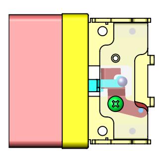
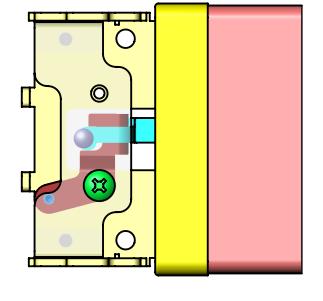
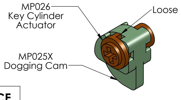
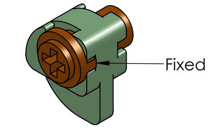
<u>Setting Night Latch or Hold Back Function:</u>
Isolate MP025X Dogging Cam and MP026 Key Cylinder Actuator, as shown below. Position notch on the Actuator for desired function. (Left-Hand Configurations Shown.)
FIRST CHOICE BUILDING PRODUCTS
(SETTING FOR NIGHT LATCH )
(SETTING FOR HOLD BACK)
CHECK ROD OPERATION
TOP LATCH
BOTTOM LATCH
After Dogging the device:
When tripped by hand, the Top Latch should swing freely through it's travel.
If not completely free, lengthen the Top Rod by loosening the Jamb Nut and rotating the Rod counter-clockwise.
The Bottom Latch should protrude 1/16" or less beyond the bottom of the door.
To shorten the Bottom Rod, loosen the Jamb Nut and rotate the Rod clockwise.
After Un-dogging the device:
The Top Latch should not trip when operated by hand. If hand pressure can trip the Latch, shorten the Rod by loosening the Jamb Nut and rotating the Rod clockwise.
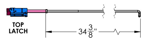
The Top Rod is factory-set to 34-3/8 ", measured from the bent end to the latch side of the Jamb Nut.
NOTE-The Bottom Rod may require adjustment to accommodate changes to the Top Rod.
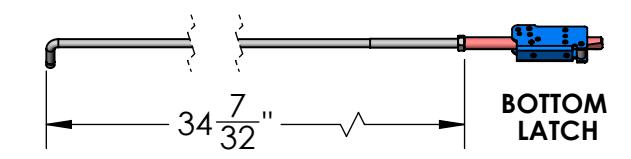
The Bottom Rod is factory-set to 34-7/32 ", measured from the bent end to the latch side of the Jamb Nut.
FIRST CHOICE
BUILDING PRODUCTS
Possible Mounting Configurations for Thick Doors & Critical Dimensions
***Regardless of Door Thickness and/or Muntin Shape provided by the customer, the following dimensions are critical for Device to function & fit properly:

MUNTIN BLOCKS CENTERED ON FRAME
Due to Muntin Block design sized for 1 3/4" Thick Door, spacers may be needed to keep Muntin and/or floating Muntin Blocks rigid. Customers may also use 1/4-20 Tapped hole in Muntin Blocks to keep Activating Assembly and Muntin rigid.
MUNTIN BLOCKS OFFSET BACKWARD
MUNTIN BLOCKS OFFSET FORWARD