Falcon_F-Series_Keyed_Locks_Installation_Instructions_-_English_106828
Open the original PDF document
View PDF
030690-000-70
F-Series Keyed Locks
FALCON ®
Installation Instructions
1. MARK DOOR
- A. Mark height line on edge of door approximately 38" from floor.
- B. Using the proper backset, mark 21/8" hole on both sides of the door.
- C. On the outside of door, mark notches.
- D. Mark the center of the door edge for the latch.
CAUTION:
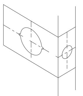
2. DOOR PREPARATION
A. Bore 21/8" hole thru from both sides of door to prevent splintering door finish. B. File notches on
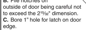
D. Using the latch faceplate as a guide, trace outline and mortise door edge so latch is flush with door.
NOTE: Hollow metal doors must be properly reinforced for lock support. If support was not furnished contact door manufacturer.
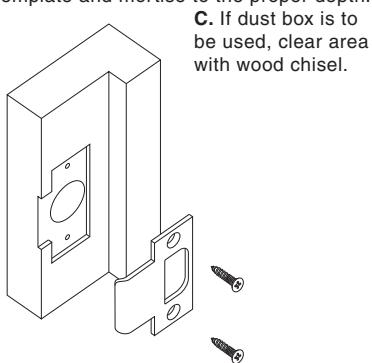
3. INSTALL STRIKE
HOLE
HOLE
A. Use strike locating tool or pointed object to locate position for hole in frame.
B. Bore 1" x 3/4" deep hole. Use strike as a template and mortise to the proper depth.
4. INSTALL LATCH SHIELD
FOR UL LATCH OPTION ONLY
A. Insert latch shield (closed end first) from the outside of the door.
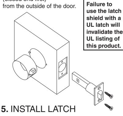
A. Insert latch into door, making certain that bevel faces direction of closing door.
B. Secure with two #8 combo screws provided.
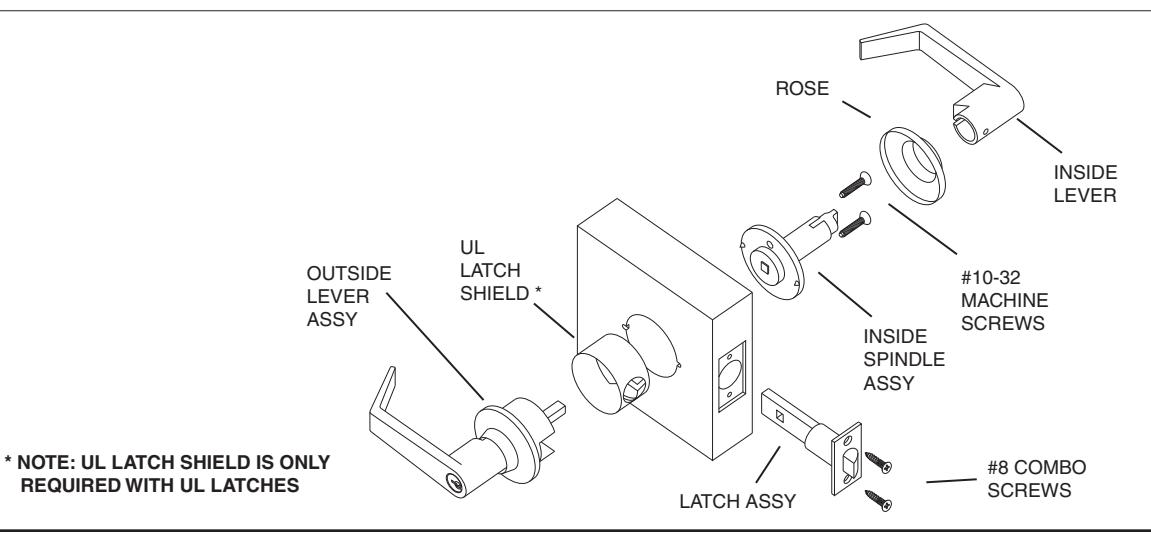
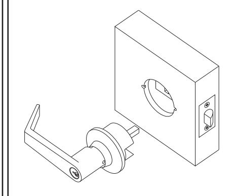
6. INSTALL OUTER TRIM
A. Align spindle with latch unit and insert outer trim into door.
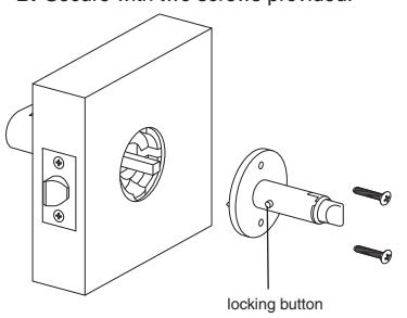
7. INSTALL INNER SPINDLE ASSEMBLY
A. Align spindle assembly with square shaft and slide into place.
NOTE: Locking button must be positioned towards the edge of the door.
B. Secure with two screws provided.

TEMPLATE FALCON F-SERIES LOCKS

8. INSTALL INSIDE TRIM
- A. Snap rose over mounting plate.
- B. Place lever on spindle and slide to locking button.
- C. Push lever in until button engages hole in lever.
- D. Check function before closing door.

9. REMOVING STANDARD CYLINDERS & LEVERS
- A. Insert key and turn 90° counter-clockwise to unlock lockset.
- B. Depress locking button and pull off lever and cylinder.

10. INSTALLING STANDARD CYLINDERS & LEVERS
- A. Insert cylinder into lever.
- B. Insert key into cylinder.
- C. With notches of key facing up, align hole in lever with locking button on spindle assy and slide lever to locking button.
- D. Push lever until lever engages button.
- E. Check function before closing door.

11. REMOVING IC CORE
- A. Unlock lockset.
- B. Turn control key 15 degrees clockwise until key stops.
- C. Pull key to remove IC core.

12. REMOVING IC LEVERS
A. With IC core removed, depress locking button and pull lever to remove.
13. INSTALL IC LEVERS
- A. Slide tailpiece assembly into spindle, engaging the single leg with the drive cam in the spindle.
- B. Insert spindle cap into the lever, notched end first.
- C. Push lever in until locking button engages hole in lever.
- D. With control key in core rotate key 15° clockwise and insert fully into lever. Turn the key counter-clockwise and remove key.
- E. Check function before

14. TAILPIECE INSTALLATION
- A. Insert spring and pin into cylinder.
- B. Place tailpiece into cap.
- C. Thread cap onto the cylinder.
NOTE: The cap must be properly adjusted. If too loose, excessive plug end play will prevent the key from being withdrawn. If too tight, the plug will drag and be difficult to rotate with the key.


BEGINNING SHEET
|
|
4.250 | ||
|---|---|---|---|
| FRON | IT | 3.670 | |
| 1 |
| Additional No | otes: | ||
|---|---|---|---|
| 1. None | |||
| Revision History | Revision Description: | ||||||||
|---|---|---|---|---|---|---|---|---|---|
| Α | В | С | D | Е | F | D > Revised artwork | |||
| 4600-304 | 0790 | 6683 | |||||||
| Material White Paper | Edited By | Approved By | EC Number | Release Date | |||||
| J. Ellis | M. Roberts | xxxxx | 10/14 | ||||||
| Notes | Notes | Title | |||||||
|
F-Series Keyed Locks | ||||||||
| 3. tolerance ± .13 | Creation Date | Number | Revision | ||||||
| 4. printed in country may vary | 10-22-14 030690-000-70 | D | |||||||
|
Created By
J. Ellis |
Activity
3899 Hancock Expwy |
• | ||||||
| Software: InDesign CS6 | 1 Committee CO 00011 | Allegion 2014 | |||||||