Falcon_212 _Series_Escutcheon_Lever_Trim_Installation_Instruction_112162
Open the original PDF document
View PDF


47260190
212 Series Escutcheon Lever Trim
Lever Escutcheon (L) Key locks and unlocks lever Night Latch Escutcheon (L-NL) Key retracts latch bolt
Installation Instructions

Door Applications
Single Door with Rim Exit Device

Double Door with one Rim Exit Device and one Surface Vertical Rod Exit Device

Double Door with Two RIm Exit Devices and Removable Mullion

Double Door with two Surface Vertical Rod Exit Devices


Trim Handing
- If the handle is knob type, trim handing is not required. Skip to step 1.
- 1. For lever type handle, rotate lever handle to right or left direction to match desired door handing (see Fig. 1)
- 2. Insert the square spindle into the hub (see Fig. 2).
- 3. Proceed with Exit Device instructions.


Fig. 2
Install mortise cylinder.
For Blank Escutcheon Trim and Dummy Escutcheon Trim, skip to step 2.
- a. Slide wave washer and cylinder collar onto mortise cylinder body (see Fig. 3).
- b. Screw cylinder into escutcheon trim with cam positioned up (see Fig. 4).
- c. Install cylinder locking plate and fasten with provided screws (see Fig 5).


Fig. 4

Fig. 5
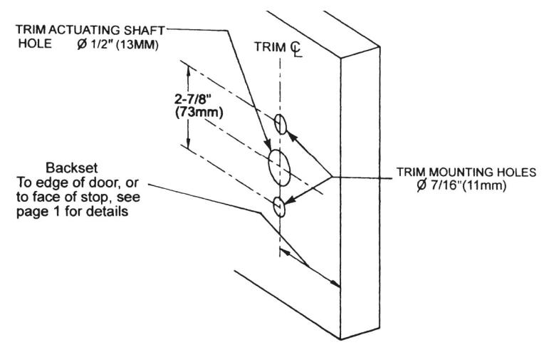
Mark and drill mounting holes on door.
- a. Mark horizontal centerline by matching it to the centerline of the exit device. Exit device centerline can be found on the inside face of the door.
- b. Apply template to the door aligned to centerline. Refer to "Door Applications" on page 1 to determine the location of the vertical centerline. The vertical centerline should match the centerline of the exit device located on the inside face of the door.
- c. Mark and drill 7/16" holes for mounting posts as shown on the template.
- d. Mark and drill 1/2" hole for the trim actuating shaft (tailpiece). The trim actuating shaft mates with the exit device. See exit device instructions for details.
3
Install escutcheon trim.
-
If necessary, install the exit device chassis before installing the escutcheon trim. Mark, drill and tap mounting holes (C and D), then install exit device chassis.
- a. Insert trim mounting posts and trim actuating shaft (tailpiece) through the door.
- b. Connect the trim actuating shaft with the cam on back of the exit device chassis.
- c. Fasten the trim from the device chassis with provided screws.
- d. Test installation by operating the lever (or knob) handle, or the key. Verify that lever or knob trim activates the exit device.
- · Dummy trim handle does not rotate.
