Falcon T Series Service Manual 108002
Open the original PDF document
View PDF

T-Series
Service manual
Contents
- Introduction
- Changes
- Lock Assembly Index
- Chassis assemblies
- Passage latchset
- Privacy hospital lock
- Closet lock
- Closet lock IC
- Classroom security lock
- Classroom security lock IC
- Asylum lock
- Asylum lock IC
- Entry lock
- Entry lock IC
- Entry/office lock
- Entry/office lock IC
- Office lock
- Office lock IC
- Classroom lock
- Classroom lock IC
- Dormitory lock
- Dormitory lock IC
- Storeroom lock
- Storeroom lock IC
- Storeroom lock (electrified fail safe)
- Storeroom lock (electrified fail safe) IC
- Storeroom lock (electrified fail secure)
- Storeroom lock (electrified fail secure) IC
- Trim assemblies
- Passage latchset
- Privacy hospital lock
- Privacy lock
- Closet lock
- Classroom security lock
- Asylum lock
- Entry lock
- Entry/office lock
- Office lock
- Classroom lock
- Dormitory lock
- Storeroom lock
- Storeroom lock (electrified fail safe)
- Storeroom lock (electrified fail secure)
- Dummy trim
- Parts and Accessories
- Standard cylinders
- IC cylinders
- Spindles
- Spring cage replacement kits
- Levers
- Latches
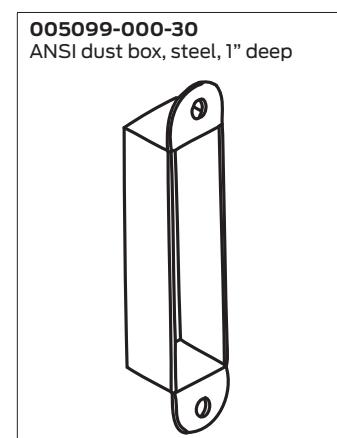
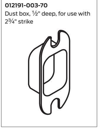
- Strikes and dust boxes
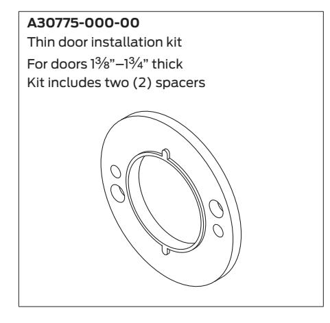
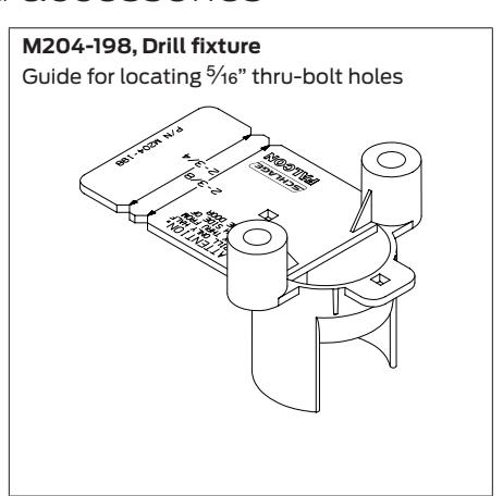
- Miscellaneous parts and accessories
- Installation Instructions
- Warranty
Introduction
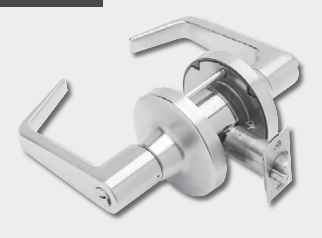
This manual contains a complete listing of T-Series (Grade 1) cylindrical lock parts and assemblies manufactured by Falcon Lock. This edition lists components of T-Series locks manufactured after July 2007.
Exploded views of each lock chassis and trim assembly are provided with an accompanying chart to identify parts for replacement purposes. In addition, this manual provides general cylinder information, many auxiliary components of the T-Series cylindrical locks and installation instructions.
Standard features*
| Certification | ANSI A156.2, Series 4000, Grade 1, UL Listed for 3-hour fire door. |
|---|---|
| Latch | 1Z" x 2Z\v", Square corner faceplate, 1" housing diameter, Z\x" throw. |
| Strike | 1Z\v" x 4M", ANSI, Square corner, no box. |
| Backset | 2C\v" |
| Cylinder | 6-Pin solid brass, keyed 5-pin, Falcon G keyway, keyed different (KD) |
| Door Range | 1C\v" – 2Z" standard |
| Keys | Two nickel silver cut keys per lock, keyed 5-pin, Falcon G keyway |
* Locks are furnished with standard features unless otherwise specified.
Lock assembly drawing index
The lock assembly drawing index provides visual representations and textual descriptions of available functions. Page numbers for full trim and chassis drawings are referenced.
Changes
Standard square corner spring latches and dead latches are updated with new part numbers and illustrations (where applicable). Other miscellaneous updates include part number updates for T851, T851-IC, T881 and T881-IC chassis and IC cylinder tailpieces.
Lock Assembly Index
| Function | ANSI A156.2, 1996, Series 4000, Grade 1 | Chassis | ||||
|---|---|---|---|---|---|---|
| Falcon | ANSI | Description | Outside function | Inside function | ||
| T101 | F75 | Passage/closet latch | Lever is always unlocked. |
Lever is always unlocked and is
always free for immediate egress. |
33 | 8 |
| T291 | Privacy hospital lock |
Latch bolt retracted by lever unless
locked by inside push-button. Unlocked from outside by turning emergency release turn-button. |
Push-button locks outside lever.
Turning inside lever or closing door releases push-button. Inside lever is always free for immediate egress. |
34 | 9 | |
| T301 | F76 | Privacy lock |
Can be opened from outside with
small screwdriver or emergency release tool. |
Push-button locks outside lever.
Turning inside lever or closing door releases push-button. Inside lever is always free for immediate egress. |
35 | 9 |
| T351 | Closet lock |
Latch bolt retracted by lever except
when locked by key. |
Knurled knob free for immediate
egress unless outside lever locked by key. |
36 |
10
11 (IC) |
|
| T381 | F88 | Classroom security lock |
Latch bolt is retracted by key in
outside lever when locked by key from inside. Outside key only retracts latch bolt. |
Key locks or unlocks outside lever.
Inside lever is always unlocked and is always free for immediate egress. |
37 |
12
13 (IC) |
| T411 | F87 | Asylum lock* | Lever is fixed. Entrance by key only. | Lever is fixed. Exit by key only. | 38 |
14
15 (IC) |
| T501 | F82 | Entry lock |
Lever is unlocked by key when
inside push-button is pushed. Key does not lock the lock. |
Push-button locks outside lever.
Turning inside lever releases button. Inside lever is always free for immediate egress. |
39 |
16
17 (IC) |
| T511 | F109 | Entry/office lock |
Turn/push-button: Outside lever is
locked when inside turn/ push-button is pushed and turned. Key is required to retract latch bolt until inside turn/push-button is manually unlocked. Push-button: Outside lever is locked when inside push-button is pushed until unlocked by key outside or by rotating inside lever. Key does not lock the lock. |
Turn/push-button: Pushing and
turning button locks outside lever until manually unlocked. Push-button: Pushing button locks outside lever until unlocked by turning inside lever. Inside always free for immediate egress. |
40 |
18
19 (IC) |
NOTE: Any function with deadlatch locks latchbolt when door is closed.
* Caution: Double cylinder locks on residences, and any door in any structure, which is used for egress are a life safety hazard in times of emergency and their use is not recommended. Installation should be in accordance with existing codes only,
Lock Assembly Index
| Function | ANSI A156.2, 1996, Series 4000, Grade 1 | Trim | Chassis | |||
|---|---|---|---|---|---|---|
| Falcon | ANSI | Description | Outside function | Inside function | ||
| T521 | F81 | Office lock |
Key retracts latch bolt when inside
turn button is turned. Key does not lock the lock. |
Turning button locks outside lever
until manually unlocked. Inside always free for immediate egress. |
41 |
20
21 (IC) |
| T561 | F84 | Classroom lock |
Outside lever locked or unlocked
by key. |
Inside lever is always unlocked and
always free for immediate egress. |
42 |
22
23 (IC) |
| T571 | F90 | Dormitory/corridor lock |
Outside lever locked or unlocked
by key. When locked by key it can only be unlocked by key. |
Push-button locks outside lever.
Turning lever or closing door releases button. Inside lever is always unlocked and is always free for immediate egress. |
43 |
24
25 (IC) |
| T581 | F86 | Storeroom lock | Lever is fixed. Entrance by key only. |
Inside lever is always unlocked and
is always free for immediate egress. |
44 |
26
27 (IC) |
| T851 |
Storeroom lock
(electrified – fail safe) |
Lever is continuously locked
electrically. Latch bolt retracted by lever when unlocked by switch or power failure. When locked, key retracts latch. |
Inside lever is always unlocked and
is always free for immediate egress. |
45 |
28
29 (IC) |
|
| T881 |
Storeroom lock
(electrified – fail secure) |
Lever is continuously locked
mechanically until unlocked by electric current. When locked, key retracts latch. |
Inside lever is always unlocked and
is always free for immediate egress. |
46 |
30
31 (IC) |
|
| T12 | Dummy trim | Single trim, surface mounted rigid lever. | 47 | |||
NOTE: Any function with deadlatch locks latchbolt when door is closed.
* Caution: Double cylinder locks on residences, and any door in any structure, which is used for egress are a life safety hazard in times of emergency and their use is not recommended. Installation should be in accordance with existing codes only,
- Passage latchset
- Privacy hospital lock
- Closet lock
- Closet lock IC
- Classroom security lock
- Classroom security lock IC
- Asylum lock
- Asylum lock IC
- Entry lock
- Entry lock IC
- Entry/office lock
- Entry/office lock IC
- Office lock
- Office lock IC
- Classroom lock
- Classroom lock IC
- Dormitory lock
- Dormitory lock IC
- Storeroom lock
- Storeroom lock IC
- Storeroom lock (electrified fail safe)
- Storeroom lock (electrified fail safe) IC
- Storeroom lock (electrified fail secure)
- Storeroom lock (electrified fail secure) IC
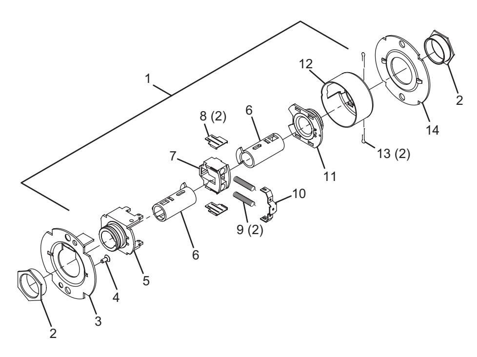
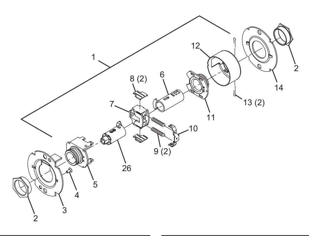
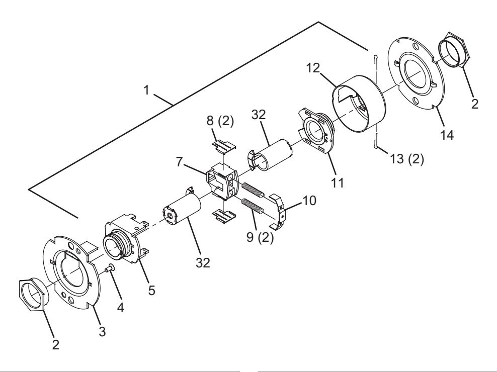
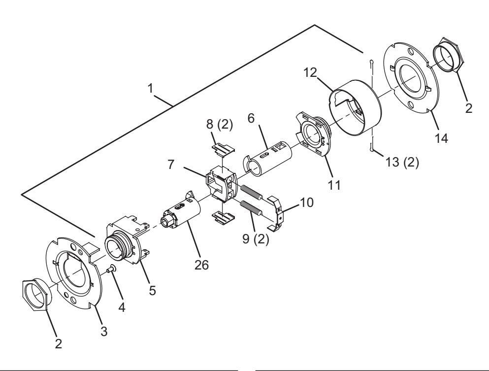
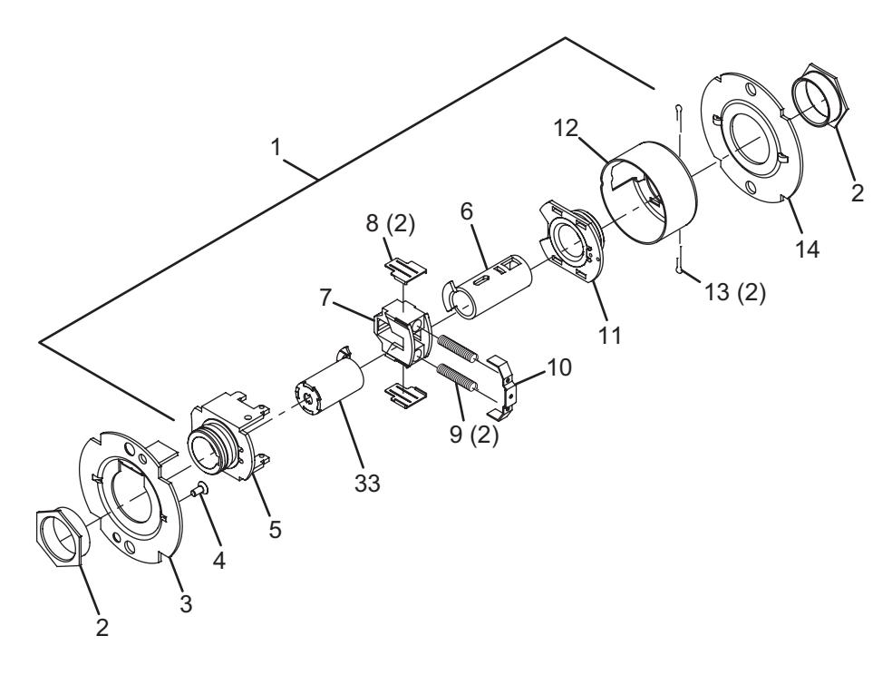
Passage latchset
| No. | Description | Part number |
|---|---|---|
| 1 | Chassis assembly, T101 | A30761-000-00 |
| 2 | Flanged nut (2) | 030726-000-30 |
| 3 | Outer mounting plate | 030712-001-30 |
| 4 | #8-32 x C" self tap screw | 031533-006-30 |
| 5 | Hub and housing assembly | A30746-000-00 |
| 6 | Spindle | 030733-000-55 |
| 7 | Retractor | 022106-002-55 |
| No. | Description | Part number |
|---|---|---|
| 8 | Retractor insert (2) | 022986-001-50 |
| 9 | Retractor spring (2) | 24064511 |
| 10 | Retractor spring retainer | 022112-000-30 |
| 11 | Hub and plate assembly | A30747-000-00 |
| 12 | Housing case | 24061772 |
| 13 | Cotter pin (2) | 002893-000-60 |
| 14 | Inner mounting plate | 030712-000-30 |
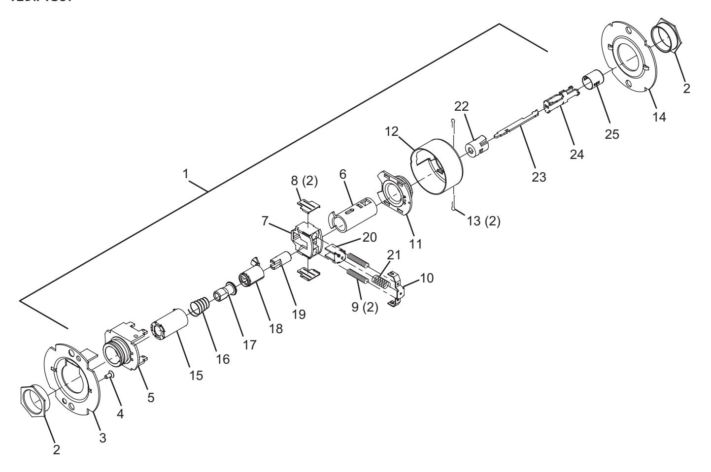
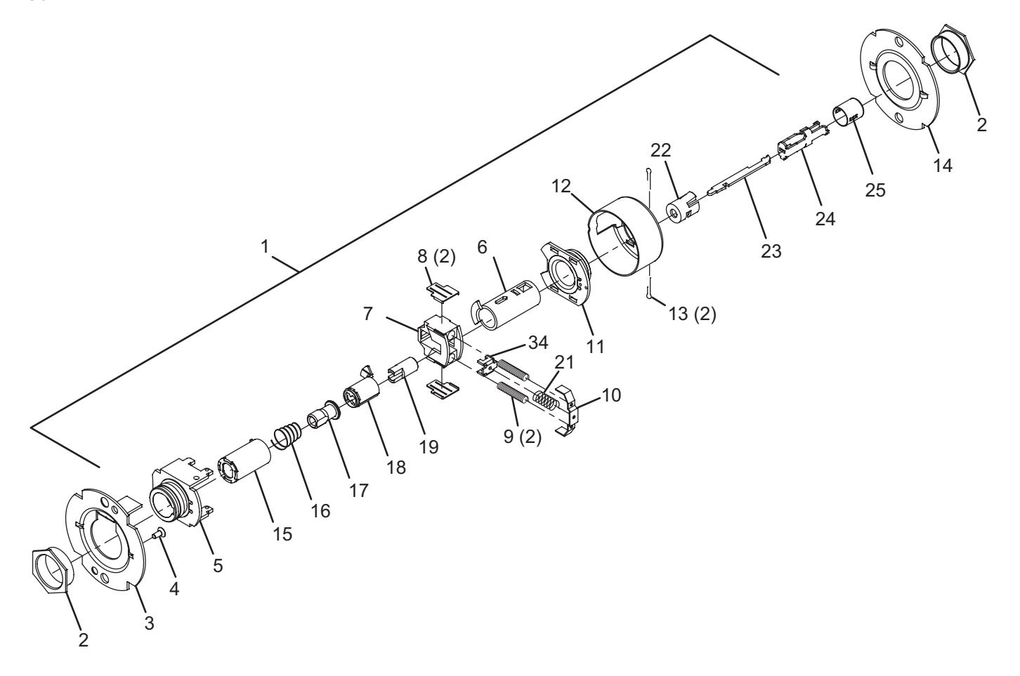
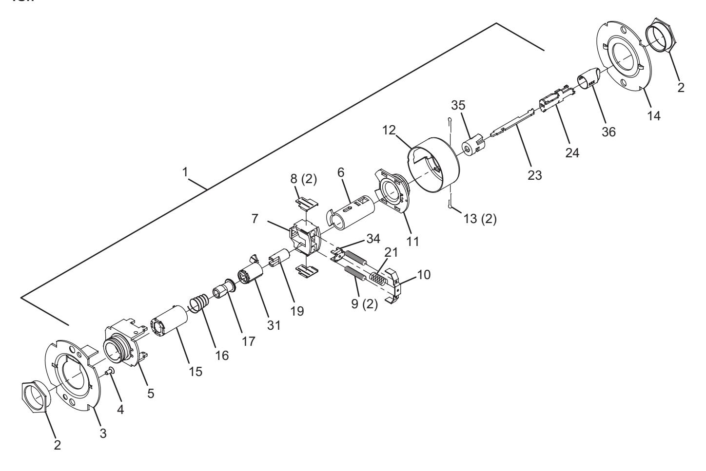
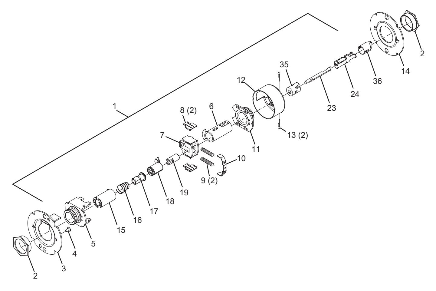
Privacy hospital lock
T291/T301
| No. | Description | Part number |
|---|---|---|
| 1 | Chassis assembly, T291/T301 | A30765-000-00 |
| 2 | Flanged nut (2) | 030726-000-30 |
| 3 | Outer mounting plate | 030712-001-30 |
| 4 | #8-32 x C" self tap screw | 031533-006-30 |
| 5 | Hub and housing assembly | A30746-000-00 |
| 6 | Spindle | 030733-000-55 |
| 7 | Retractor | 022106-002-55 |
| 8 | Retractor insert (2) | 022986-001-50 |
| 9 | Retractor spring (2) | 24064511 |
| 10 | Retractor spring retainer | 022112-000-30 |
| 11 | Hub and plate assembly | A30747-000-00 |
| 12 | Housing case | 24061772 |
| No. | Description | Part number |
|---|---|---|
| 13 | Cotter pin (2) | 002893-000-60 |
| 14 | Inner mounting plate | 030712-000-30 |
| 15 | Spindle, 1 ear, outer | 030732-005-30 |
| 16 | Clutch spring | 030709-000-60 |
| 17 | Clutch driver | 030716-001-30 |
| 18 | Key spindle, standard | 030718-000-30 |
| 19 | Push actuator | 030711-000-30 |
| 20 | Slide catch | 022105-000-30 |
| 21 | Slide catch spring | 24064529 |
| 22 | Push button sleeve | 022134-000-50 |
| 23 | Dogging bar | 030722-000-30 |
| 24 | Push/turn button mount | 030731-000-30 |
| 25 | Push button cap | 030728-000* |
* Specify finish.
Closet lock
| No. | Description | Part number |
|---|---|---|
| 1 | Chassis assembly, T351/T561 | A30758-000-00 |
| 2 | Flanged nut (2) | 030726-000-30 |
| 3 | Outer mounting plate | 030712-001-30 |
| 4 | #8-32 x C" self tapping screw | 031533-006-30 |
| 5 | Hub and housing assembly | A30746-000-00 |
| 6 | Spindle | 030733-000-55 |
| 7 | Retractor | 022106-002-55 |
| 8 | Retractor insert (2) | 022986-001-50 |
| No. | Description | Part number |
|---|---|---|
| 9 | Retractor spring (2) | 24064511 |
| 10 | Retractor spring retainer | 022112-000-30 |
| 11 | Hub and plate assembly | A30747-000-00 |
| 12 | Housing case | 24061772 |
| 13 | Cotter pin (2) | 002893-000-60 |
| 14 | Inner mounting plate | 030712-000-30 |
| 26 | Key spindle assembly, standard | A30780-000-30 |
Closet lock – IC
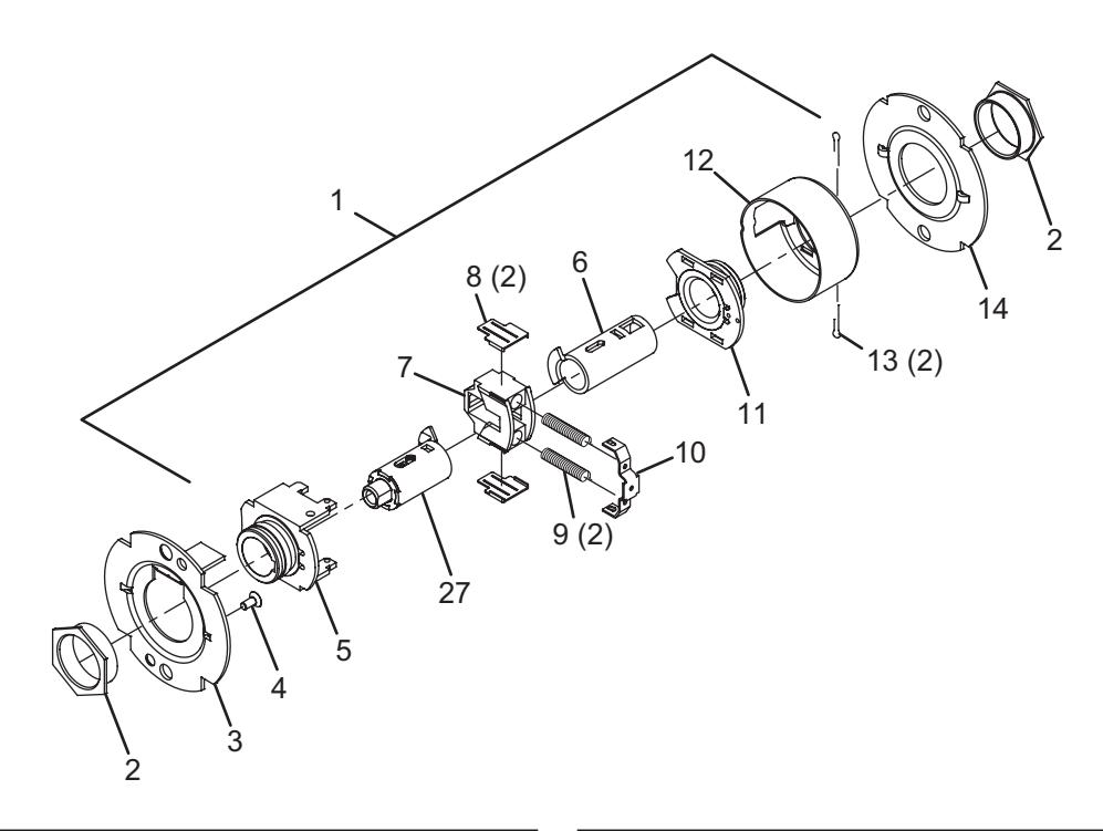
| No. | Description | Part number |
|---|---|---|
| 1 | Chassis assembly, T351/T561-IC | A30758-001-00 |
| 2 | Flanged nut (2) | 030726-000-30 |
| 3 | Outer mounting plate | 030712-001-30 |
| 4 | #8-32 x C" self tapping screw | 031533-006-30 |
| 5 | Hub and housing assembly | A30746-000-00 |
| 6 | Spindle | 030733-000-55 |
| 7 | Retractor | 022106-002-55 |
| 8 | Retractor insert (2) | 022986-001-50 |
| No. | Description | Part number |
|---|---|---|
| 9 | Retractor spring (2) | 24064511 |
| 10 | Retractor spring retainer | 022112-000-30 |
| 11 | Hub and plate assembly | A30747-000-00 |
| 12 | Housing case | 24061772 |
| 13 | Cotter pin (2) | 002893-000-60 |
| 14 | Inner mounting plate | 030712-000-30 |
| 27 | Key spindle assembly, IC | A30780-001-30 |
Classroom security lock
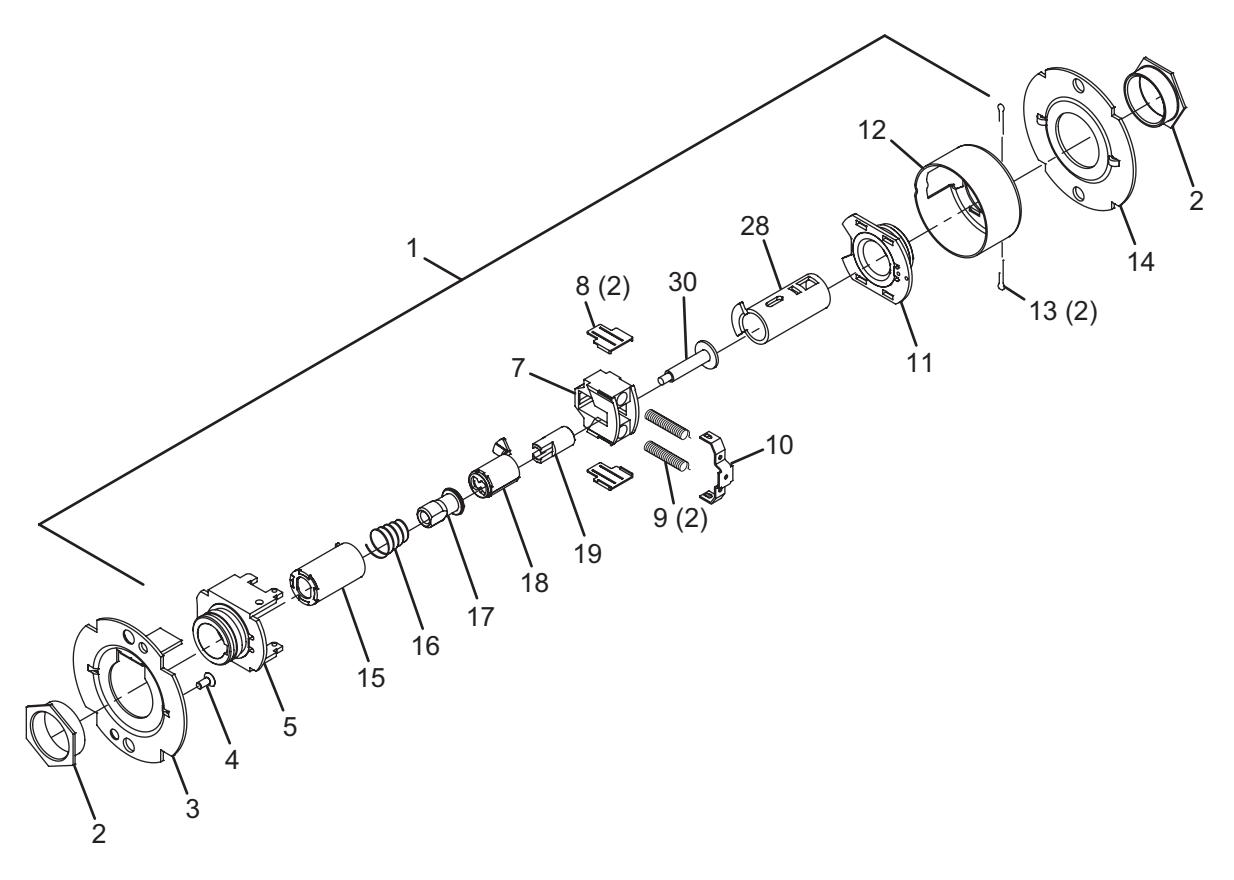
| No. | Description | Part number |
|---|---|---|
| 1 | Chassis assembly, T381 | A30767-000-00 |
| 2 | Flanged nut (2) | 030726-000-30 |
| 3 | Outer mounting plate | 030712-001-30 |
| 4 | #8-32 x C" self tapping screw | 031533-006-30 |
| 5 | Hub and housing assembly | A30746-000-00 |
| 7 | Retractor | 022106-002-55 |
| 8 | Retractor insert (2) | 022986-001-50 |
| 9 | Retractor spring (2) | 24064511 |
| 10 | Retractor spring retainer | 022112-000-30 |
| 11 | Hub and plate assembly | A30747-000-00 |
| No. | Description | Part number |
|---|---|---|
| 12 | Housing case | 24061772 |
| 13 | Cotter pin (2) | 002893-000-60 |
| 14 | Inner mounting plate | 030712-000-30 |
| 15 | Spindle, 1 ear, outer | 030732-005-30 |
| 16 | Clutch spring | 030709-000-60 |
| 17 | Clutch driver | 030716-001-30 |
| 18 | Key spindle, standard | 030718-000-30 |
| 19 | Push actuator | 030711-000-30 |
| 28 | Key spindle assembly, inside, standard | A30913-000-00 |
| 30 | Connecting rod | 030734-000-30 |
Classroom security lock – IC
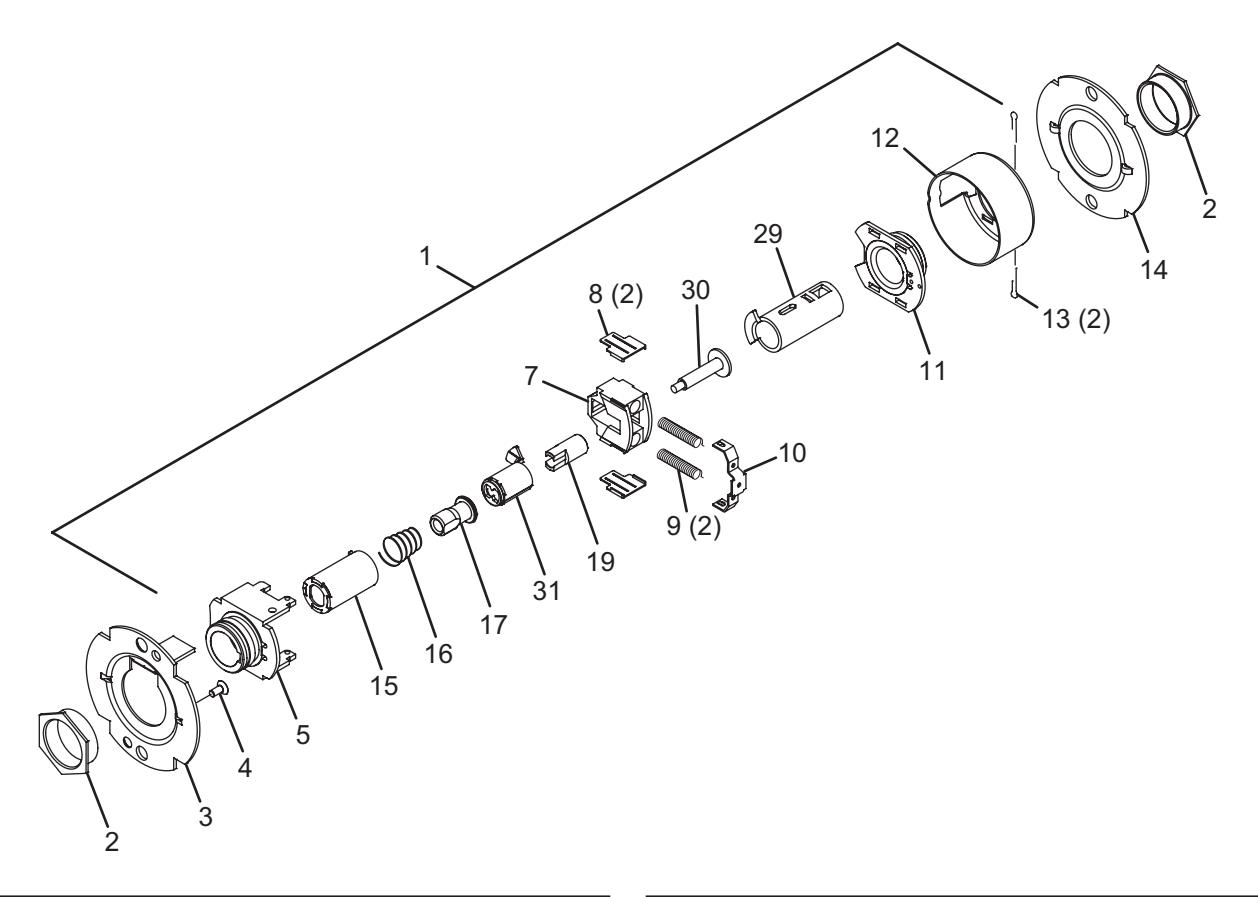
| No. | Description | Part number |
|---|---|---|
| 1 | Chassis assembly, T381 | A30767-001-00 |
| 2 | Flanged nut (2) | 030726-000-30 |
| 3 | Outer mounting plate | 030712-001-30 |
| 4 | #8-32 x C" self tapping screw | 031533-006-30 |
| 5 | Hub and housing assembly | A30746-000-00 |
| 7 | Retractor | 022106-002-55 |
| 8 | Retractor insert (2) | 022986-001-50 |
| 9 | Retractor spring (2) | 24064511 |
| 10 | Retractor spring retainer | 022112-000-30 |
| 11 | Hub and plate assembly | A30747-000-00 |
| No. | Description | Part number |
|---|---|---|
| 12 | Housing case | 24061772 |
| 13 | Cotter pin (2) | 002893-000-60 |
| 14 | Inner mounting plate | 030712-000-30 |
| 15 | Spindle, 1 ear, outer | 030732-005-30 |
| 16 | Clutch spring | 030709-000-60 |
| 17 | Clutch driver | 030716-001-30 |
| 19 | Push actuator | 030711-000-30 |
| 29 | Key spindle assembly, inside, IC | A30913-001-00 |
| 30 | Connecting rod | 030734-000-30 |
| 31 | Key Spindle, IC | 030718-001-30 |
Asylum lock
| No. | Description | Part number |
|---|---|---|
| 1 | Chassis assembly, T411 | A30769-000-00 |
| 2 | Flanged nut (2) | 030726-000-30 |
| 3 | Outer mounting plate | 030712-001-30 |
| 4 | #8-32 x C" self tapping screw | 031533-006-30 |
| 5 | Hub and housing assembly | A30746-000-00 |
| 7 | Retractor | 022106-002-55 |
| 8 | Retractor insert (2) | 022986-001-50 |
| No. | Description | Part number |
|---|---|---|
| 9 | Retractor spring (2) | 24064511 |
| 10 | Retractor spring retainer | 022112-000-30 |
| 11 | Hub and plate assembly | A30747-000-00 |
| 12 | Housing case | 24061772 |
| 13 | Cotter pin (2) | 002893-000-60 |
| 14 | Inner mounting plate | 030712-000-30 |
| 32 | Spindle, 2 ear, standard | 030732-000-30 |
Asylum lock – IC

| No. | Description | Part number |
|---|---|---|
| 1 | Chassis assembly, T411-IC | A30769-001-00 |
| 2 | Flanged nut (2) | 030726-000-30 |
| 3 | Outer mounting plate | 030712-001-30 |
| 4 | #8-32 x C" self tapping screw | 031533-006-30 |
| 5 | Hub and housing assembly | A30746-000-00 |
| 7 | Retractor | 022106-002-55 |
| 8 | Retractor insert (2) | 022986-001-50 |
| No. | Description | Part number |
|---|---|---|
| 9 | Retractor spring (2) | 24064511 |
| 10 | Retractor spring retainer | 022112-000-30 |
| 11 | Hub and plate assembly | A30747-000-00 |
| 12 | Housing case | 24061772 |
| 13 | Cotter pin (2) | 002893-000-60 |
| 14 | Inner mounting plate | 030712-000-30 |
| 33 | Spindle, 2 ear, IC | 030732-001-30 |
Entry lock
| No. | Description | Part number |
|---|---|---|
| 1 | Chassis assembly, T501 | A30773-000-00 |
| 2 | Flanged nut (2) | 030726-000-30 |
| 3 | Outer mounting plate | 030712-001-30 |
| 4 | #8-32 x C" self tapping screw | 031533-006-30 |
| 5 | Hub and housing assembly | A30746-000-00 |
| 6 | Spindle | 030733-000-55 |
| 7 | Retractor | 022106-002-55 |
| 8 | Retractor insert (2) | 022986-001-50 |
| 9 | Retractor spring (2) | 24064511 |
| 10 | Retractor spring retainer | 022112-000-30 |
| 11 | Hub and plate assembly | A30747-000-00 |
| 12 | Housing case | 24061772 |
| 13 | Cotter pin (2) | 002893-000-60 |
| No. | Description | Part number |
|---|---|---|
| 14 | Inner mounting plate | 030712-000-30 |
| 15 | Spindle, 1 ear, outer | 030732-005-30 |
| 16 | Clutch spring | 030709-000-60 |
| 17 | Clutch driver | 030716-001-30 |
| 18 | Key spindle std | 030718-000-30 |
| 19 | Push actuator | 030711-000-30 |
| 21 | Slide catch spring | 24064529 |
| 22 | Push button sleeve | 022134-000-50 |
| 23 | Dogging Bar | 030722-000-30 |
| 24 | Push/turn button mount | 030731-000-30 |
| 25 | Push button cap | 030728-000* |
| 34 | Short slide catch | 022104-000-30 |
* Specify finish.
Entry lock – IC

| No. | Description | Part number |
|---|---|---|
| 1 | Chassis assembly, T501-IC | A30773-001-00 |
| 2 | Flanged nut (2) | 030726-000-30 |
| 3 | Outer mounting plate | 030712-001-30 |
| 4 | #8-32 x C" self tapping screw | 031533-006-30 |
| 5 | Hub and housing assembly | A30746-000-00 |
| 6 | Spindle | 030733-000-55 |
| 7 | Retractor | 022106-002-55 |
| 8 | Retractor insert (2) | 022986-001-50 |
| 9 | Retractor spring (2) | 24064511 |
| 10 | Retractor spring retainer | 022112-000-30 |
| 11 | Hub and plate assembly | A30747-000-00 |
| 12 | Housing case | 24061772 |
| 13 | Cotter pin (2) | 002893-000-60 |
| No. | Description | Part number |
|---|---|---|
| 14 | Inner mounting plate | 030712-000-30 |
| 15 | Spindle, 1 ear, outer | 030732-005-30 |
| 16 | Clutch spring | 030709-000-60 |
| 17 | Clutch driver | 030716-001-30 |
| 19 | Push actuator | 030711-000-30 |
| 21 | Slide catch spring | 24064529 |
| 22 | Push button sleeve | 022134-000-50 |
| 23 | Dogging bar | 030722-000-30 |
| 24 | Push/turn button mount | 030731-000-30 |
| 25 | Push button cap | 030728-000* |
| 31 | Key spindle, IC | 030718-001-30 |
| 34 | Short slide catch | 022104-000-30 |
* Specify finish.
Entry/office lock

| No. | Description | Part number |
|---|---|---|
| 1 | Chassis assembly, T511 | A30756-000-00 |
| 2 | Flanged nut (2) | 030726-000-30 |
| 3 | Outer mounting plate | 030712-001-30 |
| 4 | #8-32 x C" self tapping screw | 031533-006-30 |
| 5 | Hub and housing assembly | A30746-000-00 |
| 6 | Spindle | 030733-000-55 |
| 7 | Retractor | 022106-002-55 |
| 8 | Retractor insert (2) | 022986-001-50 |
| 9 | Retractor spring (2) | 24064511 |
| 10 | Retractor spring retainer | 022112-000-30 |
| 11 | Hub and plate assembly | A30747-000-00 |
| 12 | Housing case | 24061772 |
| No. | Description | Part number |
|---|---|---|
| 13 | Cotter pin (2) | 002893-000-60 |
| 14 | Inner mounting plate | 030712-000-30 |
| 15 | Spindle, 1 ear, outer | 030732-005-30 |
| 16 | Clutch spring | 030709-000-60 |
| 17 | Clutch driver | 030716-001-30 |
| 18 | Key spindle, standard | 030718-000-30 |
| 19 | Push actuator | 030711-000-30 |
| 21 | Slide catch spring | 24064529 |
| 23 | Dogging bar | 030722-000-30 |
| 24 | Push/turn button mount | 030731-000-30 |
| 34 | Short slide catch | 022104-000-30 |
| 35 | Turn button sleeve | 022133-000-50 |
| 36 | Turn button cap | 030727-000* |
* Specify finish.
Entry/office lock – IC
| No. | Description | Part number |
|---|---|---|
| 1 | Chassis assembly, T511-IC | A30756-001-00 |
| 2 | Flanged nut (2) | 030726-000-30 |
| 3 | Outer mounting plate | 030712-001-30 |
| 4 | #8-32 x C" self tapping screw | 031533-006-30 |
| 5 | Hub and housing assembly | A30746-000-00 |
| 6 | Spindle | 030733-000-55 |
| 7 | Retractor | 022106-002-55 |
| 8 | Retractor insert (2) | 022986-001-50 |
| 9 | Retractor spring (2) | 24064511 |
| 10 | Retractor spring retainer | 022112-000-30 |
| 11 | Hub and plate assembly | A30747-000-00 |
| 12 | Housing case | 24061772 |
| 13 | Cotter pin (2) | 002893-000-60 |
| No. | Description | Part number |
|---|---|---|
| 14 | Inner mounting plate | 030712-000-30 |
| 15 | Spindle, 1 ear, outer | 030732-005-30 |
| 16 | Clutch spring | 030709-000-60 |
| 17 | Clutch driver | 030716-001-30 |
| 19 | Push actuator | 030711-000-30 |
| 21 | Slide catch spring | 24064529 |
| 23 | Dogging bar | 030722-000-30 |
| 24 | Push/turn button mount | 030731-000-30 |
| 31 | Key spindle, IC | 030718-001-30 |
| 34 | Short slide catch | 022104-000-30 |
| 35 | Turn button sleeve | 022133-000-50 |
| 36 | Turn button cap | 030727-000* |
* Specify finish.
Office lock
| No. | Description | Part number |
|---|---|---|
| 1 | Chassis assembly, T521 | A30748-000-00 |
| 2 | Flanged nut (2) | 030726-000-30 |
| 3 | Outer mounting plate | 030712-001-30 |
| 4 | #8-32 x C" self tapping screw | 031533-006-30 |
| 5 | Hub and housing assembly | A30746-000-00 |
| 6 | Spindle | 030733-000-55 |
| 7 | Retractor | 022106-002-55 |
| 8 | Retractor insert (2) | 022986-001-50 |
| 9 | Retractor spring (2) | 24064511 |
| 10 | Retractor spring retainer | 022112-000-30 |
| 11 | Hub and plate assembly | A30747-000-00 |
| 12 | Housing case | 24061772 |
| No. | Description | Part number |
|---|---|---|
| 13 | Cotter pin (2) | 002893-000-60 |
| 14 | Inner mounting plate | 030712-000-30 |
| 15 | Spindle, 1 ear, outer | 030732-005-30 |
| 16 | Clutch spring | 030709-000-60 |
| 17 | Clutch driver | 030716-001-30 |
| 18 | Key spindle, standard | 030718-000-30 |
| 19 | Push actuator | 030711-000-30 |
| 23 | Dogging bar | 030722-000-30 |
| 24 | Push/turn button mount | 030731-000-30 |
| 35 | Turn button sleeve | 022133-000-50 |
| 36 | Turn button cap | 030727-000* |
* Specify finish.
Office lock – IC

| No. | Description | Part number |
|---|---|---|
| 1 | Chassis assembly, T521-IC | A30748-001-00 |
| 2 | Flanged nut (2) | 030726-000-30 |
| 3 | Outer mounting plate | 030712-001-30 |
| 4 | #8-32 x C" self tapping screw | 031533-006-30 |
| 5 | Hub and housing assembly | A30746-000-00 |
| 6 | Spindle | 030733-000-55 |
| 7 | Retractor | 022106-002-55 |
| 8 | Retractor insert (2) | 022986-001-50 |
| 9 | Retractor spring (2) | 24064511 |
| 10 | Retractor spring retainer | 022112-000-30 |
| 11 | Hub and plate assembly | A30747-000-00 |
| 12 | Housing case | 24061772 |
| No. | Description | Part number |
|---|---|---|
| 13 | Cotter pin (2) | 002893-000-60 |
| 14 | Inner mounting plate | 030712-000-30 |
| 15 | Spindle, 1 ear, outer | 030732-005-30 |
| 16 | Clutch spring | 030709-000-60 |
| 17 | Clutch driver | 030716-001-30 |
| 19 | Push actuator | 030711-000-30 |
| 23 | Dogging bar | 030722-000-30 |
| 24 | Push/turn button mount | 030731-000-30 |
| 31 | Key spindle, IC | 030718-001-30 |
| 35 | Turn button sleeve | 022133-000-50 |
| 36 | Turn button cap | 030727-000* |
* Specify finish.
Classroom lock
| No. | Description | Part number |
|---|---|---|
| 1 | Chassis assembly, T351/T561 | A30758-000-00 |
| 2 | Flanged nut (2) | 030726-000-30 |
| 3 | Outer mounting plate | 030712-001-30 |
| 4 | #8-32 x C" self tapping screw | 031533-006-30 |
| 5 | Hub and housing assembly | A30746-000-00 |
| 6 | Spindle | 030733-000-55 |
| 7 | Retractor | 022106-002-55 |
| 8 | Retractor insert (2) | 022986-001-50 |
| No. | Description | Part number |
|---|---|---|
| 9 | Retractor spring (2) | 24064511 |
| 10 | Retractor spring retainer | 022112-000-30 |
| 11 | Hub and plate assembly | A30747-000-00 |
| 12 | Housing case | 24061772 |
| 13 | Cotter pin (2) | 002893-000-60 |
| 14 | Inner mounting plate | 030712-000-30 |
| 26 | Key spindle assembly, standard | A30780-000-30 |
Classroom lock – IC

| No. | Description | Part number |
|---|---|---|
| 1 | Chassis assembly, T351/T561-IC | A30758-001-00 |
| 2 | Flanged nut (2) | 030726-000-30 |
| 3 | Outer mounting plate | 030712-001-30 |
| 4 | #8-32 x C" self tapping screw | 031533-006-30 |
| 5 | Hub and housing assembly | A30746-000-00 |
| 6 | Spindle | 030733-000-55 |
| 7 | Retractor | 022106-002-55 |
| 8 | Retractor insert (2) | 022986-001-50 |
| No. | Description | Part number |
|---|---|---|
| 9 | Retractor spring (2) | 24064511 |
| 10 | Retractor spring retainer | 022112-000-30 |
| 11 | Hub and plate assembly | A30747-000-00 |
| 12 | Housing case | 24061772 |
| 13 | Cotter pin (2) | 002893-000-60 |
| 14 | Inner mounting plate | 030712-000-30 |
| 27 | Key spindle assembly, IC | A30780-001-30 |
Dormitory lock
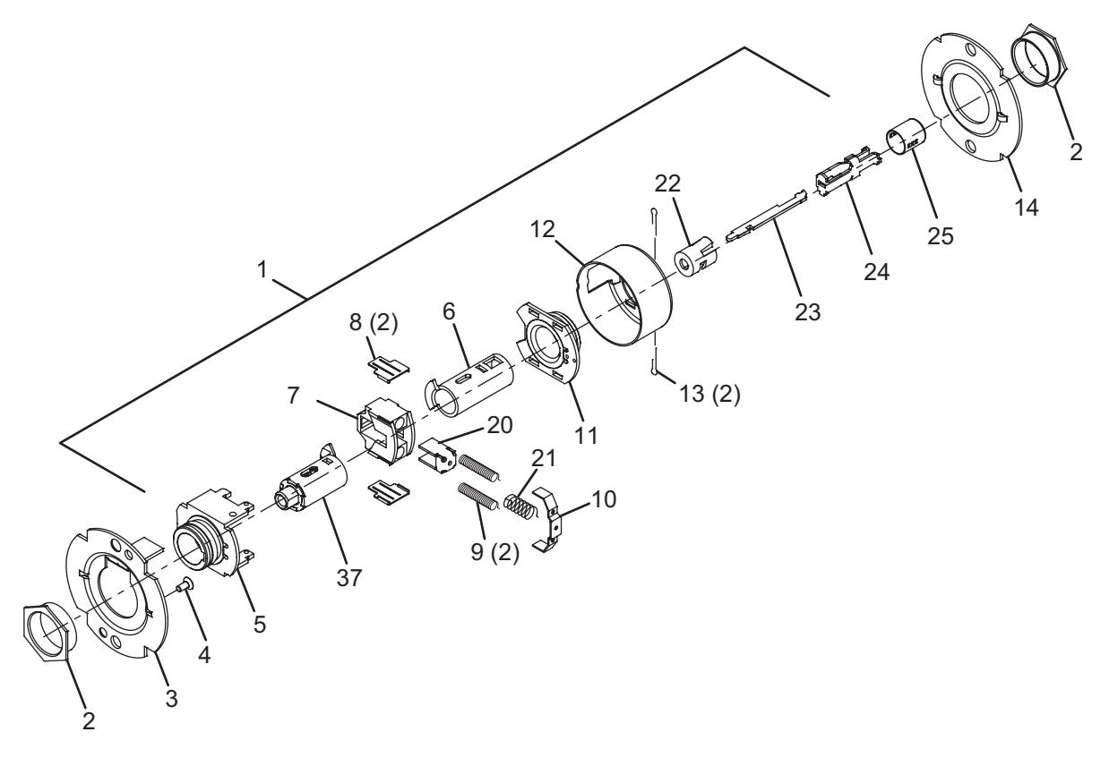
| No. | Description | Part number |
|---|---|---|
| 1 | Chassis assembly, T571 | A30759-000-00 |
| 2 | Flanged nut (2) | 030726-000-30 |
| 3 | Outer mounting plate | 030712-001-30 |
| 4 | #8-32 x C" self tapping screw | 031533-006-30 |
| 5 | Hub and housing assembly | A30746-000-00 |
| 6 | Spindle | 030733-000-55 |
| 7 | Retractor | 022106-002-55 |
| 8 | Retractor insert (2) | 022986-001-50 |
| 9 | Retractor spring (2) | 24064511 |
| 10 | Retractor spring retainer | 022112-000-30 |
| 11 | Hub and plate assembly | A30747-000-00 |
| No. | Description | Part number |
|---|---|---|
| 12 | Housing case | 24061772 |
| 13 | Cotter pin (2) | 002893-000-60 |
| 14 | Inner mounting plate | 030712-000-30 |
| 20 | Slide catch | 022105-000-30 |
| 21 | Slide catch spring | 24064529 |
| 22 | Push button sleeve | 022134-000-50 |
| 23 | Dogging bar | 030722-000-30 |
| 24 | Push/turn button mount | 030731-000-30 |
| 25 | Push button cap | 030728-000* |
| 37 | Key spindle assembly, T571, standard | A30915-000-00 |
* Specify finish.
Dormitory lock – IC
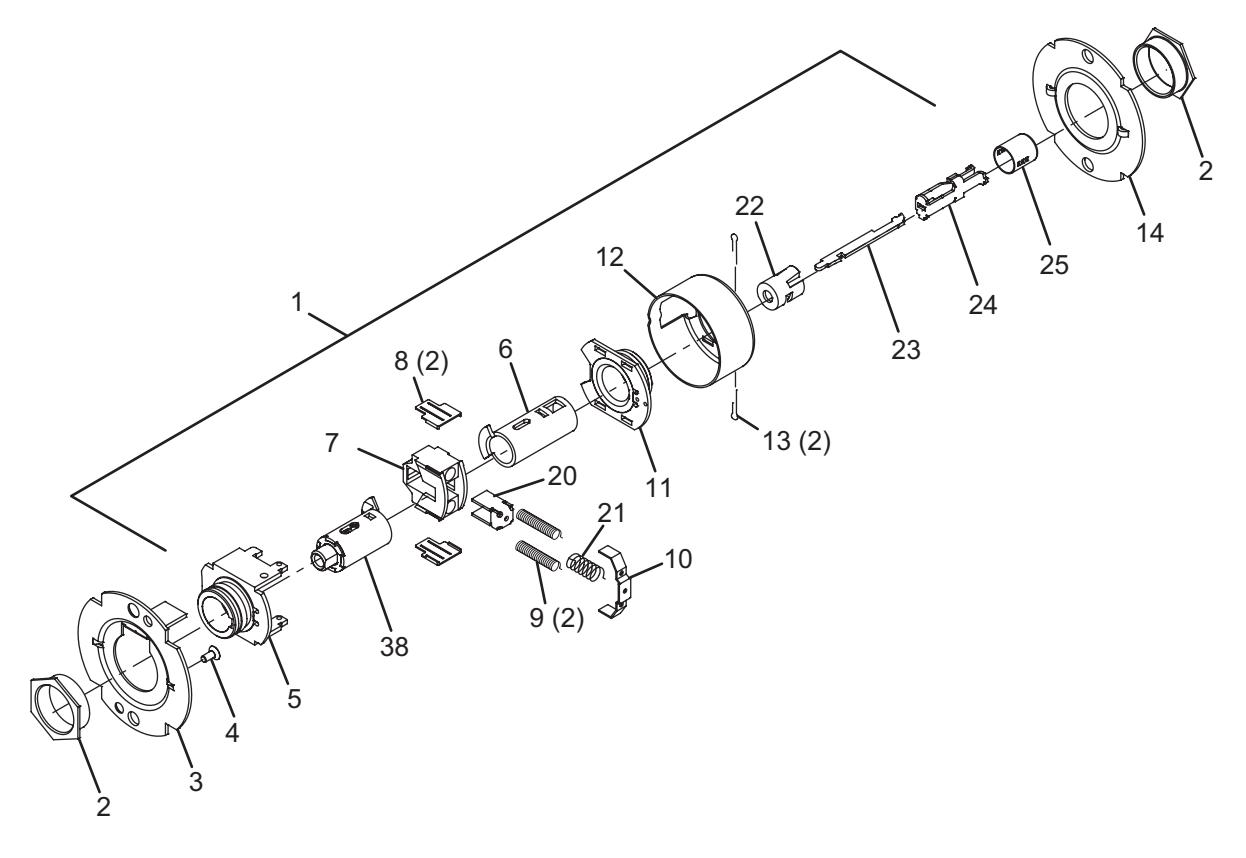
| No. | Description | Part number |
|---|---|---|
| 1 | Chassis assembly, T571-IC | A30759-001-00 |
| 2 | Flanged nut (2) | 030726-000-30 |
| 3 | Outer mounting plate | 030712-001-30 |
| 4 | #8-32 x C" self tapping screw | 031533-006-30 |
| 5 | Hub and housing assembly | A30746-000-00 |
| 6 | Spindle | 030733-000-55 |
| 7 | Retractor | 022106-002-55 |
| 8 | Retractor insert (2) | 022986-001-50 |
| 9 | Retractor spring (2) | 24064511 |
| 10 | Retractor spring retainer | 022112-000-30 |
| 11 | Hub and plate assembly | A30747-000-00 |
| No. | Description | Part number |
|---|---|---|
| 12 | Housing case | 24061772 |
| 13 | Cotter pin (2) | 002893-000-60 |
| 14 | Inner mounting plate | 030712-000-30 |
| 20 | Slide catch | 022105-000-30 |
| 21 | Slide catch spring | 24064529 |
| 22 | Push button sleeve | 022134-000-50 |
| 23 | Dogging bar | 030722-000-30 |
| 24 | Push/turn button mount | 030731-000-30 |
| 25 | Push button cap | 030728-000* |
| 38 | Key spindle assembly, T571, IC | A30915-001-00 |
* Specify finish.
Storeroom lock
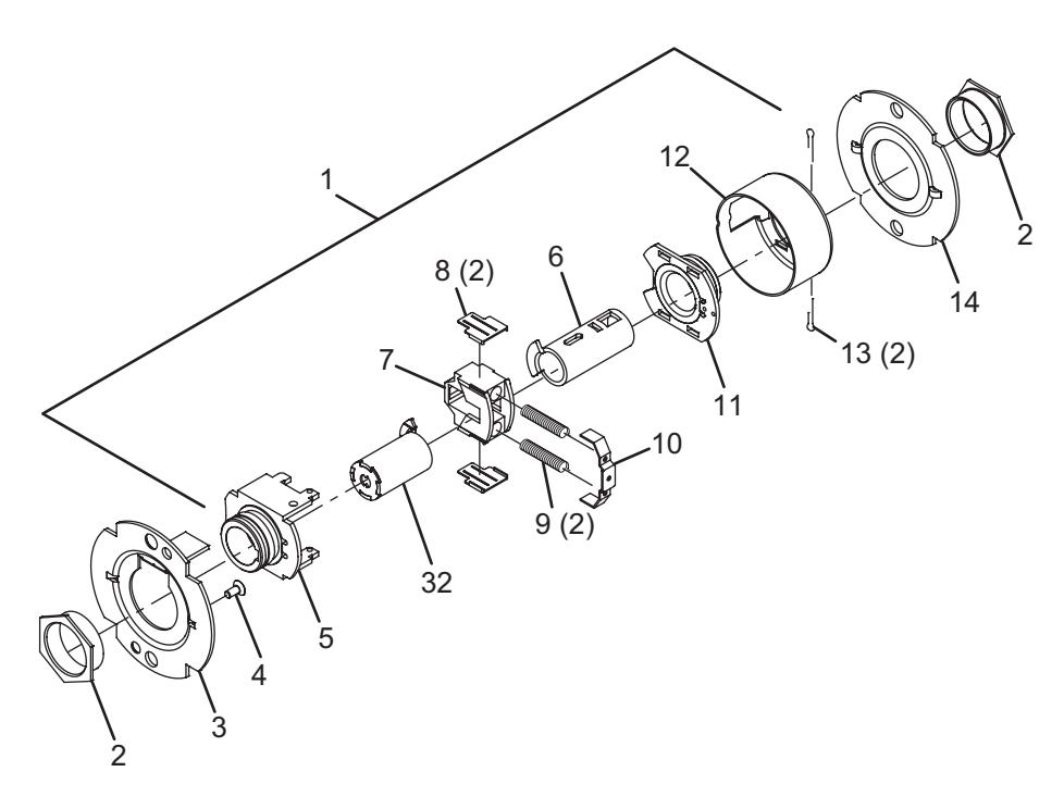
| No. | Description | Part number |
|---|---|---|
| 1 | Chassis assembly, T581 | A30760-000-00 |
| 2 | Flanged nut (2) | 030726-000-30 |
| 3 | Outer mounting plate | 030712-001-30 |
| 4 | #8-32 x C" self tapping screw | 031533-006-30 |
| 5 | Hub and housing assembly | A30746-000-00 |
| 6 | Spindle | 030733-000-55 |
| 7 | Retractor | 022106-002-55 |
| 8 | Retractor insert (2) | 022986-001-50 |
| No. | Description | Part number |
|---|---|---|
| 9 | Retractor spring (2) | 24064511 |
| 10 | Retractor spring retainer | 022112-000-30 |
| 11 | Hub and plate assembly | A30747-000-00 |
| 12 | Housing case | 24061772 |
| 13 | Cotter pin (2) | 002893-000-60 |
| 14 | Inner mounting plate | 030712-000-30 |
| 32 | Spindle, 2 ear, standard | 030732-000-30 |
Storeroom lock – IC
| No. | Description | Part number |
|---|---|---|
| 1 | Chassis assembly, T581-IC | A30760-001-00 |
| 2 | Flanged nut (2) | 030726-000-30 |
| 3 | Outer mounting plate | 030712-001-30 |
| 4 | #8-32 x C" self tapping screw | 031533-006-30 |
| 5 | Hub and housing assembly | A30746-000-00 |
| 6 | Spindle | 030733-000-55 |
| 7 | Retractor | 022106-002-55 |
| 8 | Retractor insert (2) | 022986-001-50 |
| No. | Description | Part number |
|---|---|---|
| 9 | Retractor spring (2) | 24064511 |
| 10 | Retractor spring retainer | 022112-000-30 |
| 11 | Hub and plate assembly | A30747-000-00 |
| 12 | Housing case | 24061772 |
| 13 | Cotter pin (2) | 002893-000-60 |
| 14 | Inner mounting plate | 030712-000-30 |
| 33 | Spindle, 2 ear, IC | 030732-001-00 |
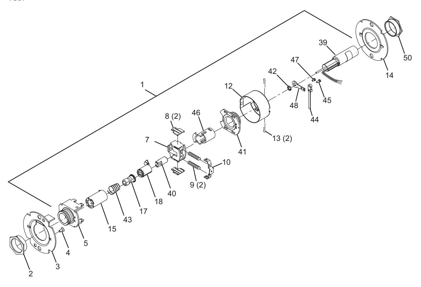
Storeroom lock (electrified – fail safe)
| No. | Description | Part number |
|---|---|---|
| 1 | Chassis assembly, T851 | A31517-000-00 |
| 2 | Flanged nut | 030726-000-30 |
| 3 | Outer mounting plate | 030712-001-30 |
| 4 | #8-32 x C" self tapping screw | 031533-006-30 |
| 5 | Hub and housing assembly | A30746-000-00 |
| 7 | Retractor | 022106-002-55 |
| 8 | Retractor insert (2) | 022986-001-50 |
| 9 | Retractor spring (2) | 24064511 |
| 10 | Retractor spring retainer | 022112-000-30 |
| 12 | Housing case | 24061798 |
| 13 | Cotter pin (2) | 002893-000-60 |
| 14 | Inner mounting plate | 030712-000-30 |
| 15 | Splindle, 1 ear, outside | 030732-005 |
| No. | Description | Part number |
|---|---|---|
| 17 | Clutch driver | 24368706 |
| 18 | Key spindle, standard | 030718-000-30 |
| 39 | Solenoid | 031516-000 |
| 40 | Push acutator, electrified lock | 030711-001-30 |
| 41 | Hub and plate assembly, electrified | A31538-001-00 |
| 42 | Special nut, Z\v - 28 | 031511-000-30 |
| 43 | Clutch spring | 030709-002 |
| 44 | Modified cable tie | Q001-088-70 |
| 45 | Fillister head 4-40 x Z\v screw | 031515-004-30 |
| 46 | Spindle, inside, T851/T881 | 030733-002-55 |
| 47 | Fillister head 4-40 x Z screw | Q001-087 |
| 48 | Solenoid mounting plate | 031514-000-30 |
| 50 | Flanged nut, inside, electrified | 030726-007-30 |
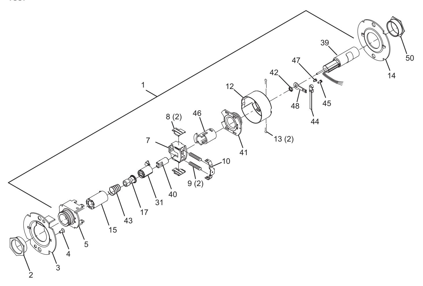
Storeroom lock (electrified – fail safe) – IC

| No. | Description | Part number |
|---|---|---|
| 1 | Chassis assembly, T851-IC | A31517-001-00 |
| 2 | Flanged Nut | 030726-000-30 |
| 3 | Outer mounting plate | 030712-001-30 |
| 4 | #8-32 x C" self tapping screw | 031533-006-30 |
| 5 | Hub and housing assembly | A30746-000-00 |
| 7 | Retractor | 022106-002-55 |
| 8 | Retractor insert (2) | 022986-001-50 |
| 9 | Retractor spring (2) | 24064511 |
| 10 | Retractor spring retainer | 022112-000-30 |
| 12 | Housing case | 24061798 |
| 13 | Cotter pin (2) | 002893-000-60 |
| 14 | Inner mounting plate | 030712-000-30 |
| 15 | Spindle, 1 ear, outer | 030732-005-30 |
| No. | Description | Part number |
|---|---|---|
| 17 | Clutch driver | 24368706 |
| 31 | Key spindle, IC | 030718-001 |
| 39 | Solenoid | 031516-000 |
| 40 | Push acutator, electrified lock | 030711-001-30 |
| 41 | Hub and plate assembly, electrified | A31538-001-00 |
| 42 | Special nut, Z\v - 28 | 031511-000-30 |
| 43 | Clutch spring | 030709-001-30 |
| 44 | Modified cable tie | Q001-088-70 |
| 45 | Fillister head 4-40 x Z\v Screw | 031515-004-30 |
| 46 | Spindle, inside, T851/T881 | 030733-002-55 |
| 47 | Fillister head 4-40 x Z Screw | Q001-087 |
| 48 | Solenoid mounting plate | 031514-000-30 |
| 50 | Flanged nut, inside, electrified | 030726-007-30 |
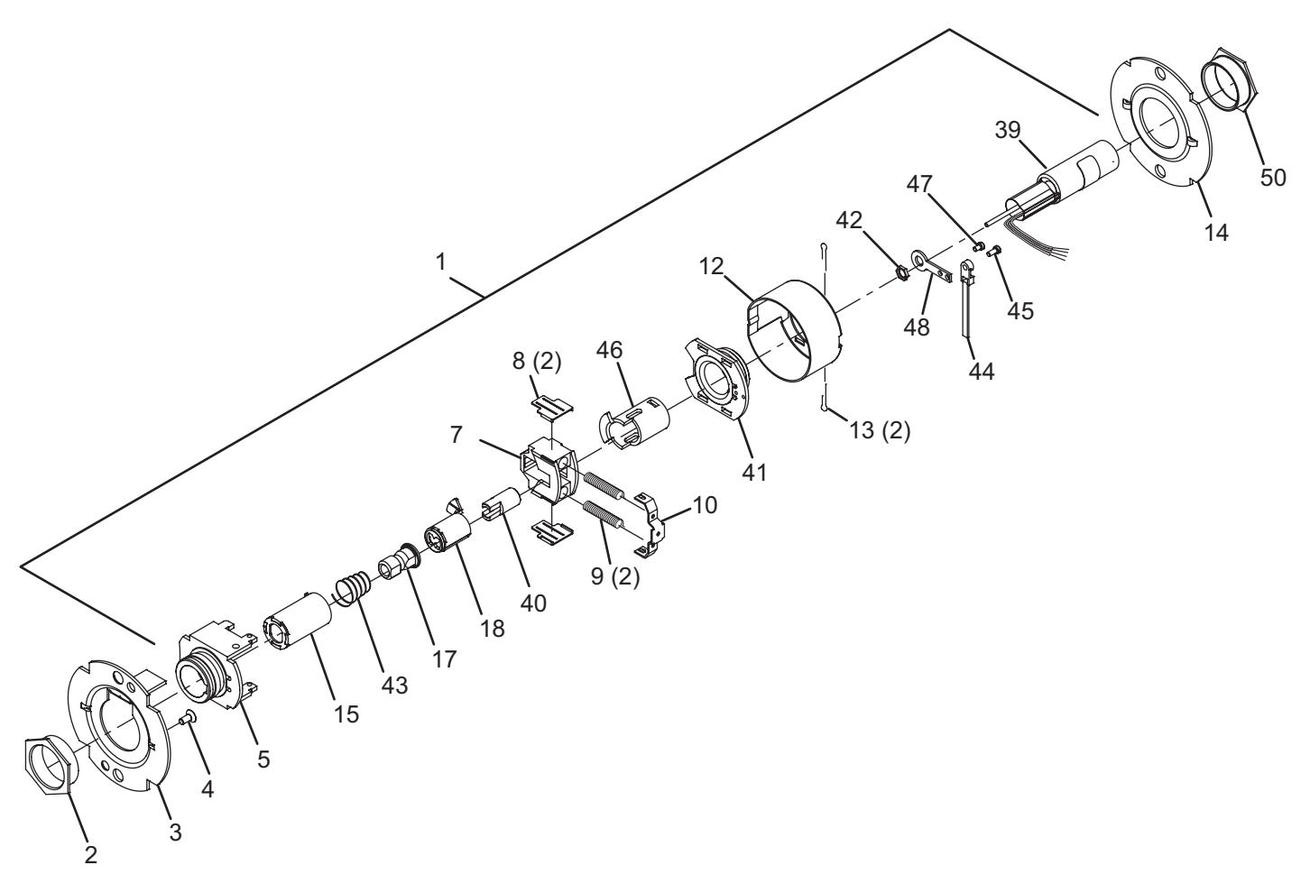
Storeroom lock (electrified – fail secure)
| No. | Description | Part number |
|---|---|---|
| 1 | Chassis assembly, T881 | A31518-000-00 |
| 2 | Flanged Nut | 030726-000-30 |
| 3 | Outer mounting plate | 030712-001-30 |
| 4 | #8-32 x C" Self tap screw | 031533-006-30 |
| 5 | Hub and housing assembly | A30746-000-00 |
| 7 | Retractor | 022106-002-55 |
| 8 | Retractor insert (2) | 022986-001-50 |
| 9 | Retractor spring (2) | 24064511 |
| 10 | Retractor spring retainer | 022112-000-30 |
| 12 | Housing case | 24061798 |
| 13 | Cotter pin (2) | 002893-000-60 |
| 14 | Inner mounting plate | 030712-000-30 |
| 15 | Spindle, 1 ear, outer | 030732-005-30 |
| No. | Description | Part number |
|---|---|---|
| 17 | Clutch driver | 030716-001-30 |
| 18 | Key spindle, standard | 030718-000-30 |
| 39 | Solenoid | 031516-000 |
| 40 | Push acutator, electrified lock | 030711-001-30 |
| 41 | Hub and plate assembly, electrified | A31538-001-00 |
| 42 | Special nut, Z\v - 28 | 031511-000-30 |
| 43 | Clutch spring | 030709-001-30 |
| 44 | Modified cable tie | Q001-088-70 |
| 45 | Fillister head 4-40 x Z\v screw | 031515-004-30 |
| 46 | Spindle, inside, T851/T881 | 030733-002-55 |
| 47 | Fillister head 4-40 x Z screw | Q001-087 |
| 48 | Solenoid mounting plate | 031514-000-30 |
| 50 | Flanged nut, inside, electrified | 030726-007-30 |
Storeroom lock (electrified – fail secure) – IC
| No. | Description | Part number |
|---|---|---|
| 1 | Chassis assembly, T881-IC | A31518-001-00 |
| 2 | Flanged Nut | 030726-000-30 |
| 3 | Outer mounting plate | 030712-001-30 |
| 4 | #8-32 x C" Self tap screw | 031533-006-30 |
| 5 | Hub and housing assembly | A30746-000-00 |
| 7 | Retractor | 022106-002-55 |
| 8 | Retractor insert (2) | 022986-001-50 |
| 9 | Retractor spring (2) | 24064511 |
| 10 | Retractor spring retainer | 022112-000-30 |
| 12 | Housing case | 24061798 |
| 13 | Cotter pin (2) | 002893-000-60 |
| 14 | Inner mounting plate | 030712-000-30 |
| 15 | Spindle, 1 ear, outer | 030732-005-30 |
| No. | Description | Part number |
|---|---|---|
| 17 | Clutch driver | 030716-001-30 |
| 39 | Solenoid | 031516-000 |
| 40 | Push acutator, electrified lock | 030711-001-30 |
| 41 | Hub and plate assembly, electrified | A31538-001-00 |
| 42 | Special nut, Z\v - 28 | 031511-000-30 |
| 43 | Clutch spring | 030709-001-30 |
| 44 | Modified cable tie | Q001-088-70 |
| 45 | Fillister head 4-40 x Z\v screw | 031515-004-30 |
| 46 | Spindle, inside, T851/T881 | 030733-002-55 |
| 47 | Fillister head 4-40 x Z screw | Q001-087 |
| 48 | Solenoid mounting plate | 031514-000-30 |
| 50 | Flanged nut, inside, electrified | 030726-007-30 |
- Passage latchset
- Privacy hospital lock
- Privacy lock
- Closet lock
- Classroom security lock
- Asylum lock
- Entry lock
- Entry/office lock
- Office lock
- Classroom lock
- Dormitory lock
- Storeroom lock
- Storeroom lock (electrified fail safe)
- Storeroom lock (electrified fail secure)
- Dummy trim
Passage latchset
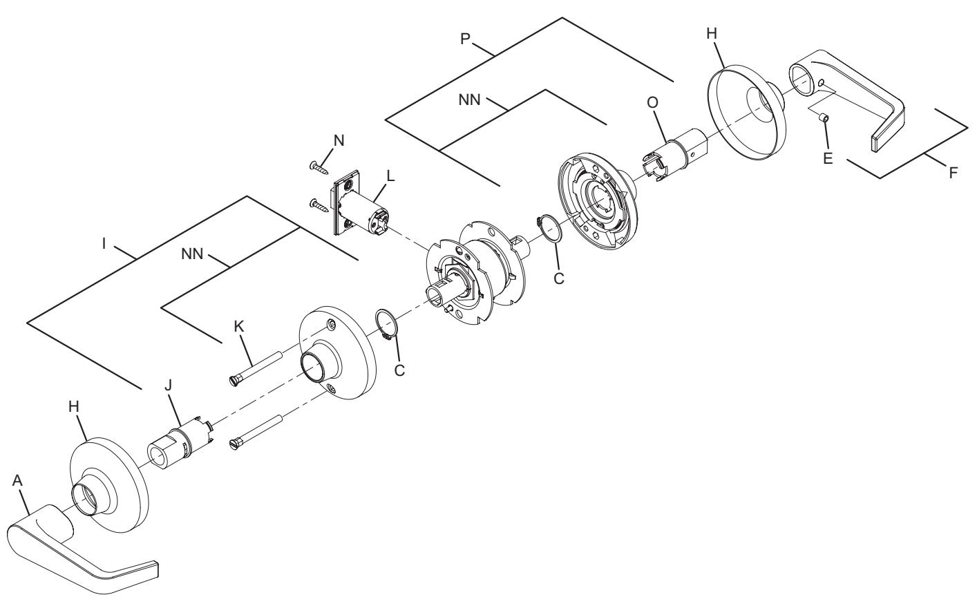
Note: spring cage components require lubrication. See page 51 for specifications.
| No. | Description | Part number |
|---|---|---|
| A | Closed lever, outside | see page 52 |
| C | Lever retaining ring | 030724-000-30 |
| E | Lever set screw | 030831-004-30 |
| F | Closed lever and set screw assembly | A30753-00X* |
| H | Rose | 030706-002* |
| I |
Spring cage and spindle, outside,
passage |
A30749-000-00 |
| J | Spindle, outside, passage | A30906-000-00 |
| No. | Description | Part number |
|---|---|---|
| K | Mounting post (2) | 030715-000-30 |
| L | Spring latch | 23981137* |
| N | #8-32 x C\v" combo screw | 024416-012* |
| O | Spindle, inside, passage/button | 030703-000-30 |
| P |
Spring cage and spindle, inside,
passage/button |
A30750-000-00 |
| NN | Non-locking spring cage | Q330-271 |
* Specify finish.
Privacy hospital lock
T291
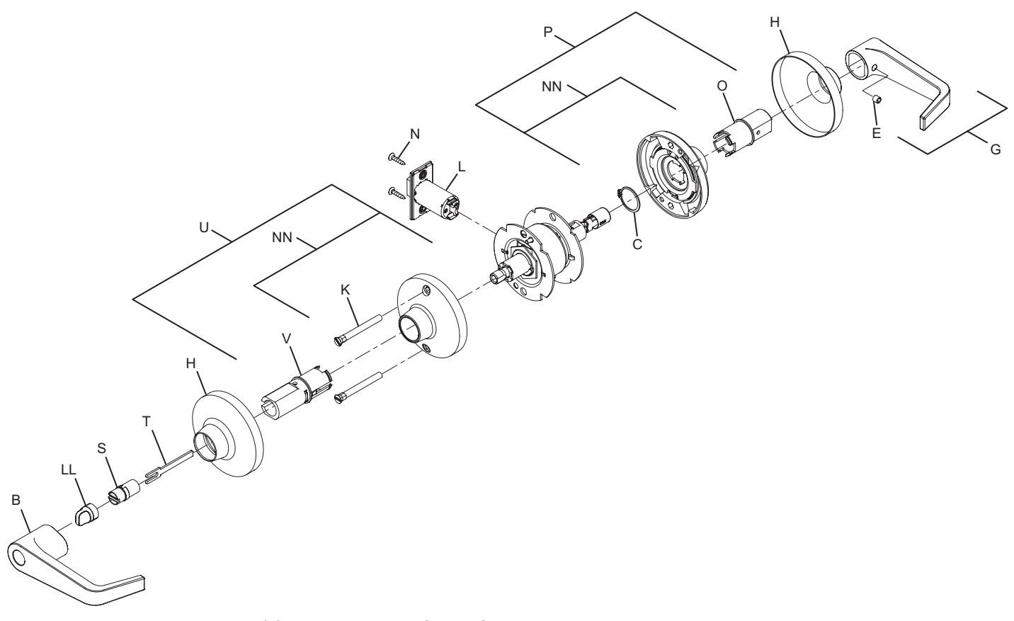
Note: spring cage components require lubrication. See page 51 for specifications.
| No. | Description | Part number |
|---|---|---|
| B | Open lever, outside | see page 52 |
| C | Lever retaining ring | 030724-000-30 |
| E | Lever set screw | 030831-004-30 |
| G | Open lever and set screw assembly | A30753-01X* |
| H | Rose | 030706-002* |
| K | Mounting post (2) | 030715-000-30 |
| L | Spring latch | 23981137* |
| N | #8-32 x C\v" combo screw | 024416-012* |
| O | Spindle, inside, passage/button | 030703-000-30 |
| No. | Description | Part number |
|---|---|---|
| P |
Spring cage and spindle, inside,
passage/button |
A30750-000-00 |
| S | Outer button mount | 030729-000-70 |
| T | Tailpiece, 6-pin IC | 030739-000-30 |
| U |
Spring cage and spindle, outside,
button |
A30796-000-00 |
| V | Spindle, outside, button | A30905-000-00 |
| LL | Button, T291, outside | Q033-044* |
| NN | Non-locking spring cage | Q330-271 |
* Specify finish.
Privacy lock
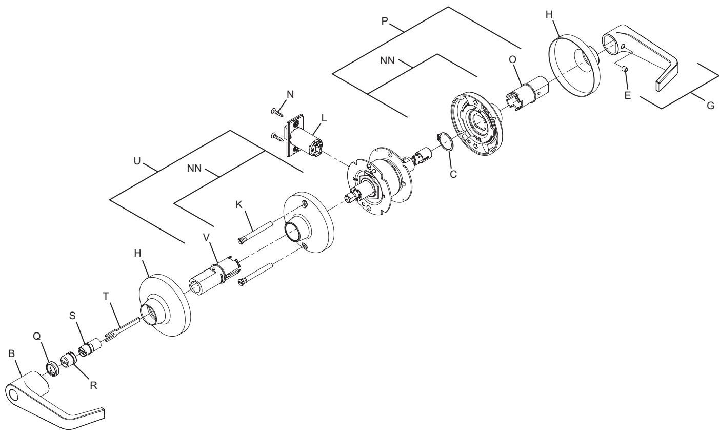
Note: Spring Cage components require lubrication. See page 51 for specifications.
| No. | Description | Part number |
|---|---|---|
| B | Open lever, outside | see page 52 |
| C | Lever retaining ring | 030724-000-30 |
| E | Lever set screw | 030831-004-30 |
| G | Open lever and set screw assembly | A30753-01X* |
| H | Rose | 030706-002* |
| K | Mounting post (2) | 030715-000-30 |
| L | Spring latch | 23981137* |
| N | #8-32 x C\v" combo screw | 024416-012* |
| O | Spindle, inside, passage/button | 030703-000-30 |
| No. | Description | Part number |
|---|---|---|
| P |
Spring cage and spindle, inside,
passage/button |
A30750-000-00 |
| Q | Button spacer | 030787-000-70 |
| R | Emergency release cap | 030654-000* |
| S | Outer button mount | 030729-000-70 |
| T | Tailpiece, 6-pin IC | 030739-000-30 |
| U |
Spring cage and spindle, outside,
button |
A30796-000-00 |
| V | Spindle, outside, button | A30905-000-00 |
| NN | Non-locking spring cage | Q330-271 |
* Specify finish.
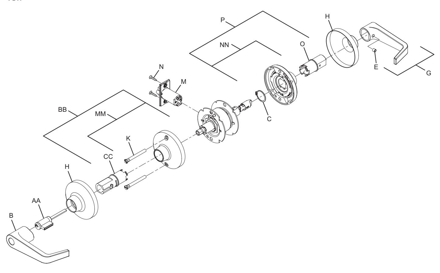
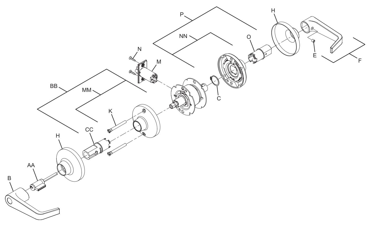
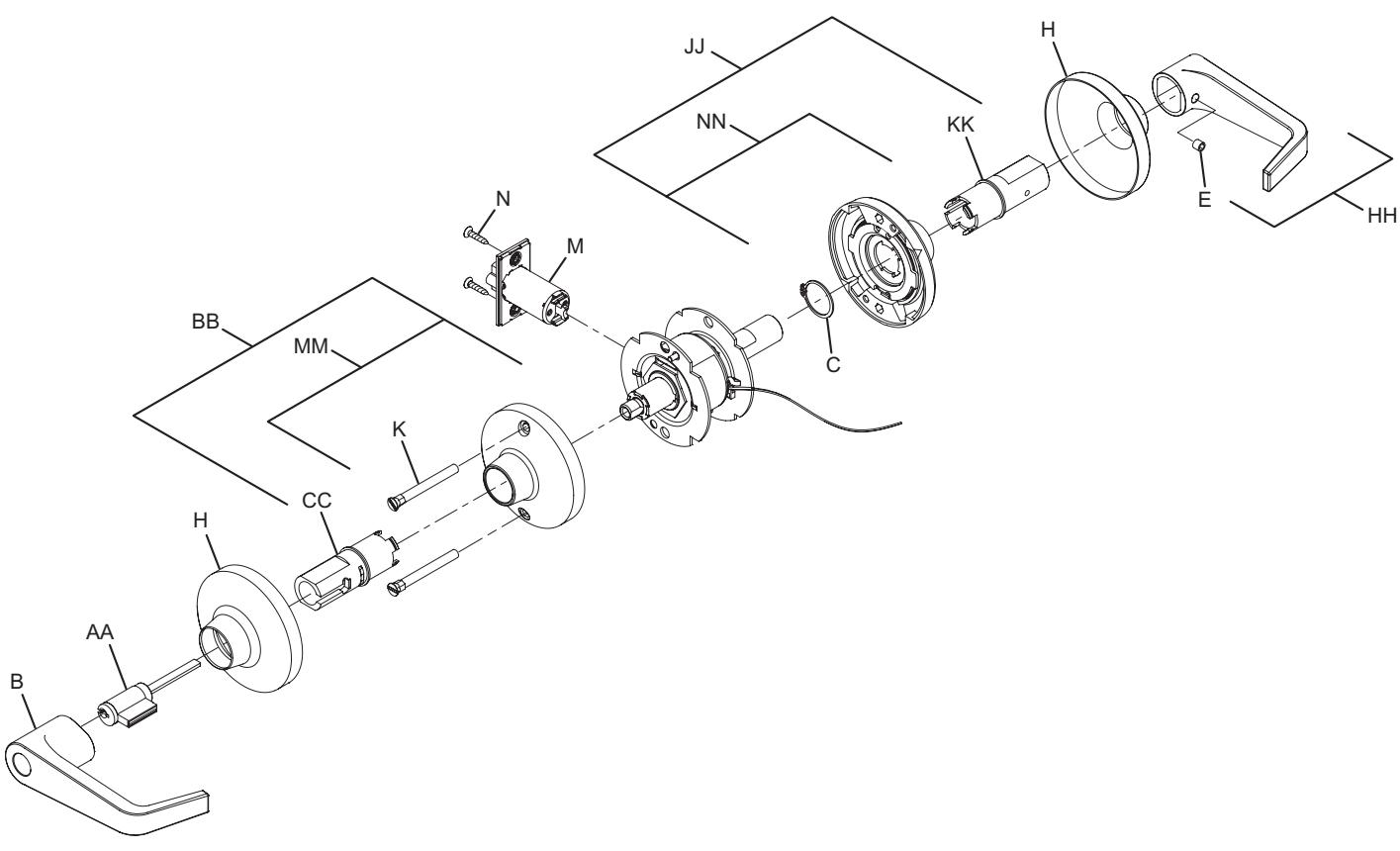
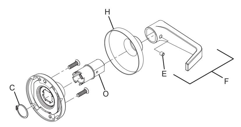
Closet lock
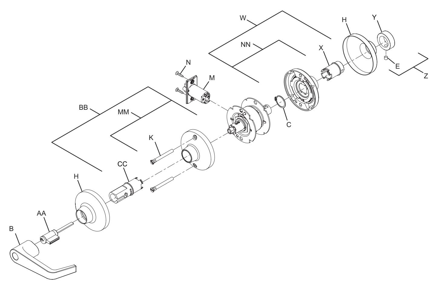
Note: Spring Cage components require lubrication. See page 51 for specifications.
| No. | Description | Part number |
|---|---|---|
| B | Open lever, outside | see page 52 |
| C | Lever retaining ring | 030724-000-30 |
| E | Lever set screw | 030831-004-30 |
| H | Rose | 030706-002* |
| K | Mounting post (2) | 030715-000-30 |
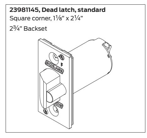
| M | Deadlatch | 23981145* |
| N | #8-32 x C\v" combo screw | 024416-012* |
| W | Spring cage and spindle, inside, T351 | A30776-001-00 |
| No. | Description | Part number |
|---|---|---|
| X | Spindle, inside, T351 | 030703-001-30 |
| Y | Turn knob, knurled | 030738-000* |
| Z | Turn knob and set screw assembly | A30788-000* |
| AA | 6-Pin cylinder | A23161-05* |
| BB |
Spring cage and spindle, outside, 6-pin
cylinder |
A30910-060-00 |
| CC | Spindle, outside, 6-pin cylinder | A30905-060-00 |
| MM | Locking spring cage | Q330-270 |
| NN | Non-locking spring cage | Q330-271 |
* Specify finish.
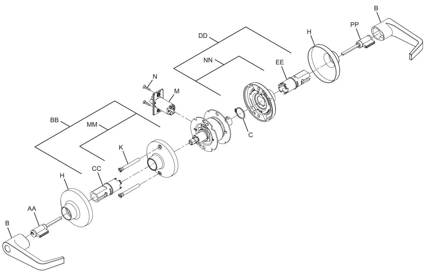
Classroom security lock
Note: Spring Cage components require lubrication. See page 51 for specifications.
| No. | Description | Part number |
|---|---|---|
| B | Open lever, outside | see page 52 |
| C | Lever retaining ring | 030724-000-30 |
| H | Rose | 030706-002* |
| K | Mounting post (2) | 030715-000-30 |
| M | Deadlatch | 23981145* |
| N | #8-32 x C\v" combo screw | 024416-012* |
| AA | 6-Pin Cylinder | A23161-05* |
| No. | Description | Part number |
|---|---|---|
| BB |
Spring cage and spindle, outside, 6-pin
cylinder |
A30910-060-00 |
| CC | Spindle, outside, 6-pin cylinder | A30905-060-00 |
| DD |
Spring cage and spindle, inside, 6-pin
cylinder |
A30779-060-00 |
| EE | Spindle, inside, 6-pin cylinder | A30906-060-00 |
| MM | Locking spring cage | Q330-270 |
| NN | Non-locking spring cage | Q330-271 |
| PP | 6-Pin Cylinder | A23161-06* |
* Specify finish.
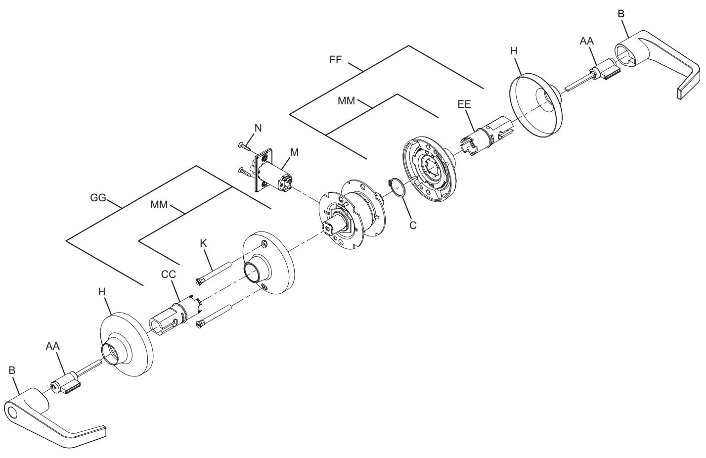
Asylum lock
Note: Spring Cage components require lubrication. See page 51 for specifications.
| No. | Description | Part number |
|---|---|---|
| B | Open lever, outside | see page 52 |
| C | Lever retaining ring | 030724-000-30 |
| H | Rose | 030706-002* |
| K | Mounting post (2) | 030715-000-30 |
| M | Deadlatch | 23981145* |
| N | #8-32 x C\v" combo screw | 024416-012* |
| AA | 6-Pin cylinder | A23161-05* |
| No. | Description | Part number |
|---|---|---|
| CC | Spindle, outside, 6-pin cylinder | A30905-060-00 |
| FF |
Spring cage and spindle, inside, 6-pin
cylinder, T411 |
A31523-060-00 |
| GG |
Spring cage and spindle, outside, 6-pin
cylinder, T411/T581 |
A30749-060-00 |
| EE | Spindle, inside, 6-pin cylinder | 030906-060-00 |
| MM | Locking spring cage | Q330-270 |
* Specify finish.
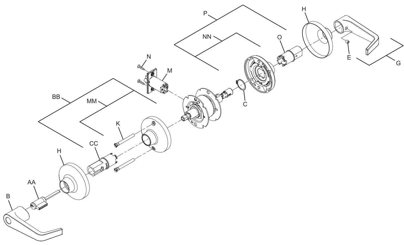
Entry lock

Note: Spring Cage components require lubrication. See page 51 for specifications.
| No. | Description | Part number |
|---|---|---|
| B | Open lever, outside | see page 52 |
| C | Lever retaining ring | 030724-000-30 |
| E | Lever set screw | 030831-004-30 |
| G | Open lever and set screw assembly | A30753-01X* |
| H | Rose | 030706-002* |
| K | Mounting post (2) | 030715-000-30 |
| M | Deadlatch | 23981145* |
| N | #8-32 x C\v" combo screw | 024416-012* |
| No. | Description | Part number |
|---|---|---|
| O | Spindle, inside, passage/button | 030703-000-30 |
| P |
Spring cage and spindle, inside,
passage/button |
A30750-000-00 |
| AA | 6-Pin cylinder | A23161-05* |
| BB |
Spring cage and spindle, outside, 6-pin
cylinder |
A30910-060-00 |
| CC | Spindle, 6-pin cylinder, outside | A30905-060-00 |
| MM | Locking spring cage | Q330-270 |
| NN | Non-locking spring cage | Q330-271 |
* Specify finish.
Entry/office lock
T511
Note: Spring Cage components require lubrication. See page 51 for specifications.
| No. | Description | Part number |
|---|---|---|
| B | Open lever, outside | see page 52 |
| C | Lever retaining ring | 030724-000-30 |
| E | Lever set screw | 030831-004-30 |
| G | Open lever and set screw assembly | A30753-01X* |
| H | Rose | 030706-002* |
| K | Mounting post (2) | 030715-000-30 |
| M | Deadlatch | 23981145* |
| N | #8-32 x C\v" combo screw | 024416-012* |
| No. | Description | Part number |
|---|---|---|
| O | Spindle, inside, passage/button | 030703-000-30 |
| P |
Spring cage and spindle, inside,
passage/button |
A30750-000-00 |
| AA | 6-Pin cylinder | A23161-05* |
| BB |
Spring cage and spindle, outside, 6-pin
cylinder |
A30910-060-00 |
| CC | Spindle, 6-pin cylinder, outside | A30905-060-00 |
| MM | Locking spring cage | Q330-270 |
| NN | Non-locking spring cage | Q330-271 |
* Specify finish.
Office lock
T521
Note: Spring Cage components require lubrication. See page 51 for specifications.
| No. | Description | Part number |
|---|---|---|
| B | Open lever, outside | see page 52 |
| C | Lever retaining ring | 030724-000-30 |
| E | Lever set screw | 030831-004-30 |
| G | Open lever and set screw assembly | A30753-01X* |
| H | Rose | 030706-002* |
| K | Mounting post (2) | 030715-000-30 |
| M | Deadlatch | 23981145* |
| N | #8-32 x C\v" combo screw | 024416-012* |
| No. | Description | Part number |
|---|---|---|
| O | Spindle, inside, passage/button | 030703-000-30 |
| P |
Spring cage and spindle, inside,
passage/button |
A30750-000-00 |
| AA | 6-Pin cylinder | A23161-05* |
| BB |
Spring cage and spindle, outside, 6-pin
cylinder |
A30910-060-00 |
| CC | Spindle, 6-pin cylinder, outside | A30905-060-00 |
| MM | Locking spring cage | Q330-270 |
| NN | Non-locking spring cage | Q330-271 |
* Specify finish.
Classroom lock
Note: Spring Cage components require lubrication. See page 51 for specifications.
| No. | Description | Part number |
|---|---|---|
| B | Open lever, outside | see page 52 |
| C | Lever retaining ring | 030724-000-30 |
| E | Lever set screw | 030831-004-30 |
| F | Closed lever and set screw assembly | A30753-00X* |
| H | Rose | 030706-002* |
| K | Mounting post (2) | 030715-000-30 |
| M | Deadlatch | 23981145* |
| N | #8-32 x C\v" combo screw | 024416-012* |
| No. | Description | Part number | |
|---|---|---|---|
| O | Spindle, inside, passage/button | 030703-000-30 | |
| P |
Spring cage and spindle, inside,
passage/button |
A30750-000-00 | |
| AA | 6-Pin cylinder | A23161-05* | |
| BB |
Spring cage and spindle, outside, 6-pin
cylinder |
A30910-060-00 | |
| CC | Spindle, 6-pin cylinder, outside | A30905-060-00 | |
| MM | Locking spring cage | Q330-270 | |
| NN | Non-locking spring cage | Q330-271 | |
* Specify finish.
Dormitory lock
Note: Spring Cage components require lubrication. See page 51 for specifications.
| No. | Description | Part number |
|---|---|---|
| B | Open lever, outside | see page 52 |
| C | Lever retaining ring | 030724-000-30 |
| E | Lever set screw | 030831-004-30 |
| G | Open lever and set screw assembly | A30753-01X* |
| H | Rose | 030706-002* |
| K | Mounting post (2) | 030715-000-30 |
| M | Deadlatch | 23981145* |
| N | #8-32 x C\v" combo screw | 024416-012* |
| No. | Description | Part number |
|---|---|---|
| O | Spindle, inside, passage/button | 030703-000-30 |
| P |
Spring cage and spindle, inside,
passage/button |
A30750-000-00 |
| AA | 6-Pin cylinder | A23161-05* |
| BB |
Spring cage and spindle, outside, 6-pin
cylinder |
A30910-060-00 |
| CC | Spindle, 6-pin cylinder, outside | A30905-060-00 |
| MM | Locking spring cage | Q330-270 |
| NN | Non-locking spring cage | Q330-271 |
* Specify finish.
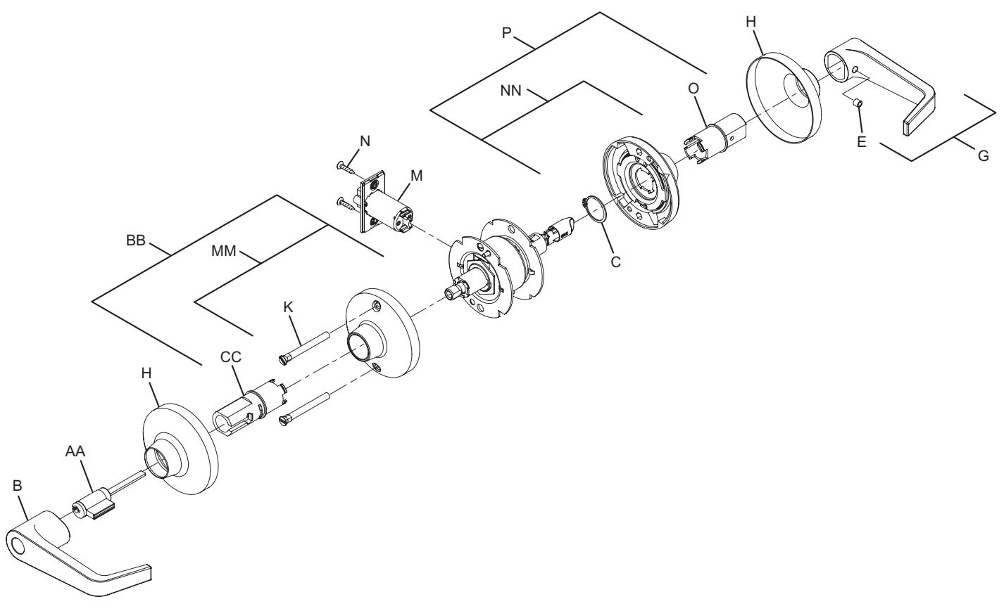
Storeroom lock
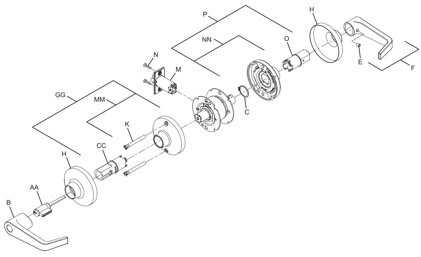
Note: Spring Cage components require lubrication. See page 51 for specifications.
| No. | Description | Part number |
|---|---|---|
| B | Open lever, outside | see page 52 |
| C | Lever retaining ring | 030724-000-30 |
| E | Lever set screw | 030831-004-30 |
| F | Closed lever and set screw assembly | A30753-00X* |
| H | Rose | 030706-002* |
| K | Mounting post (2) | 030715-000-30 |
| M | Deadlatch | 23981145* |
| N | #8-32 x C\v" combo screw | 024416-012* |
| No. | Description | Part number |
|---|---|---|
| O | Spindle, inside, passage/button | 030703-000-30 |
| P |
Spring cage and spindle, inside,
passage/button |
A30750-000-00 |
| AA | 6-Pin cylinder | A23161-05* |
| CC | Spindle, 6-pin cylinder, outside | A30906-060-00 |
| GG | Spring cage, outside, T411/F581 | A30749-060-00 |
| MM | Locking spring cage | Q330-270 |
| NN | Non-locking spring cage | Q330-271 |
* Specify finish.
Storeroom lock (electrified – fail safe)
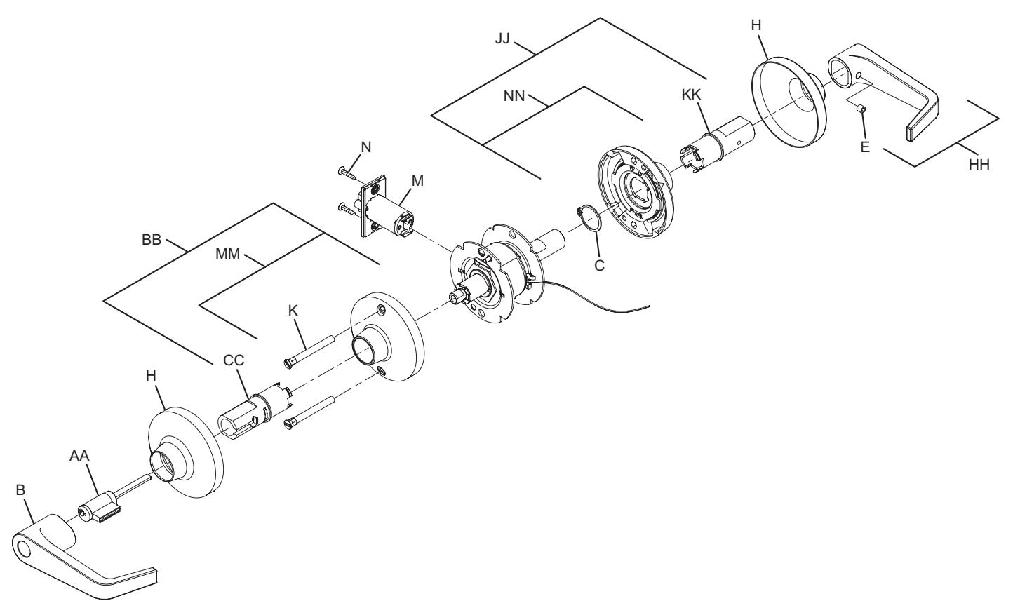
Note: Spring Cage components require lubrication. See page 51 for specifications.
| No. | Description | Part number |
|---|---|---|
| B | Open lever, outside | see page 52 |
| C | Lever retaining ring | 030724-000-30 |
| E | Lever set screw | 030831-004-30 |
| H | Rose | 030706-002* |
| K | Mounting post (2) | 030715-000-30 |
| M | Deadlatch | 23981145* |
| N | #8-32 x C\v" combo screw | 024416-012* |
| AA | 6-Pin cylinder | A23161-05* |
| No. | Description | Part number |
|---|---|---|
| BB |
Spring cage and spindle, outside, 6-pin
cylinder |
A30910-060-00 |
| CC | Spindle, outside, 6-pin cylinder | A30905-060-00 |
| HH |
T851/T881 lever and set screw
assembly |
A31544-00X* |
| JJ |
Spring cage and spindle, inside, T851/
T881 |
A31638-000-00 |
| KK | Spindle, inside, T851/T881 | 031519-000-30 |
| MM | Locking spring cage | Q330-270 |
| NN | Non-locking spring cage | Q300-271 |
* Specify finish.
Storeroom lock (electrified – fail secure)
Note: Spring Cage components require lubrication. See page 51 for specifications.
| No. | Description | Part number |
|---|---|---|
| B | Open lever, outside | see page 52 |
| C | Lever retaining ring | 030724-000-30 |
| E | Lever set screw | 030831-004-30 |
| H | Rose | 030706-002* |
| K | Mounting post (2) | 030715-000-30 |
| M | Deadlatch | 23981145* |
| N | #8-32 x C\v" combo screw | 024416-012* |
| AA | 6-Pin Cylinder | A23161-05* |
| No. | Description | Part number |
|---|---|---|
| BB |
Spring cage and spindle, outside, 6-pin
cylinder |
A30910-060-00 |
| CC | Spindle, outside, 6-pin cylinder | A30905-060-00 |
| HH |
T851/T881 lever and set screw
assembly |
A31544-00X |
| JJ |
Spring cage and spindle, inside, T851/
T881 |
A31638-000-00 |
| KK | Spindle, inside, T851/T881 | 031519-000-30 |
| MM | Locking spring cage | Q330-270 |
| NN | Non-locking spring cage | Q300-271 |
* Specify finish.
Dummy trim
T12
Note: spring cage components require lubrication. See page 51 for specifications.
| No. | Description | Part number |
|---|---|---|
| C | Lever retaining ring | 030724-000-30 |
| E | Lever set screw | 030831-004-30 |
| F | Closed lever and set screw assembly | A30753-00X* |
| No. | Description | Part number |
|---|---|---|
| H | Rose | 030706-002* |
| O | Spindle, inside, passage | 030703-000-30 |
* Specify finish.
Standard cylinders
Falcon complete standard cylinders
| Functions | |||
|---|---|---|---|
| All except T381IS, T571 | T571 | ||
| 5-Pin Cylinder | A23151-05 | A23151-06 | A23151-07 |
| 6-Pin Cylinder | A23161-05 | A23161-06 | A23161-07 |
| 7-Pin Cylinder | A23171-05 | A23171-06 | A23171-07 |
Standard cylinder options
| Description | Specify | |
|---|---|---|
| 5 pinned cylinder | P suffix | Example: T581PD |
| 6 pinned cylinder | P6 suffix | Example: T581PD6 |
| 7 pinned cylinder | P7 suffix | Example: T581PD7 |
| 6 pinned competitor keyway cylinders* | P6 suffix | Example: T581PD6 SCH C |
| 6 pinned Schlage C | CP6 suffix | Example: T581CPD6 |
Notes: Specify keyway.
Finishes 606, 620 and 622 only. (622 finish available only on Allegion cylinders (P, P6 and P7) in C and G keyways). Cylinders are furnished G keyway, keyed differently unless otherwise specified. Restricted sections require additional fee.
Standard cylinder tailpieces
| Cylinders | Std. Functions | T381 Inside | T571 |
|---|---|---|---|
| Falcon 6-pin* (10 pack) | A30730-001-00 | A30730-003-00 | A30730-002-00 |
| Falcon 7-pin (10 pack) | A30730-002-00 | A30730-004-00 | A30730-006-00 |
| Sargent 6 and 10 Line | 030997-001-30 | 030997-003-30 | 030997-005-30 |
| Yale 1801, 5801 | 030917-001-30 | 030917-003-30 | 030917-005-30 |
| Corbin Russwin | 030994-001-30 | 030994-003-30 | 030994-005-30 |
* Assa 65611 and 65661, Corbin Russwin 2000-034 and Schlage (including Primus) all use Falcon 6-pin tailpiece.
Competitor keyway compatibility
Falcon T-Series locks are furnished with Falcon's standard "G" keyway cylinder unless otherwise specified. The following competitor standard cylinders are acceptable.
- Assa (65611 or 65661) 6-pin
- Sargent (6, 7 and 10 line) 6-pin –Keso not available
- Peaks (Kaba) 6-pin
-
Medeco (20W200V3) 6-pin
- –Tailpiece supplied by Medeco
- –Falcon/Schlage style
- Schlage standard 6-pin
- Schlage Primus 6-pin
- Yale (1801) 6-pin (bicentric not available)
- Corbin Russwin (2000-034/CL3400) 6-pin
* Competitor cylinders are furnished 0-bitted unless otherwise specified, KD, KA4 only. No master keying, except Schlage C. KD option is not available for locks containing two cylinders.
IC cylinders
Falcon complete IC cylinders
| Style | Combinated | Uncombinated | ||||
|---|---|---|---|---|---|---|
| 6-Pin | 7-Pin | 6-Pin | 7-Pin | |||
| Standard | C606 | C607 | C646 | C647 | ||
|
Standard with
Best-style capping |
CB806 | CB807 | CB846 | CB847 | ||
| Style | Combinated | Uncombinated | ||||
|---|---|---|---|---|---|---|
| 6-Pin | 7-Pin | 6-Pin | 7-Pin | |||
| No logo | C608 | C609 | C648 | C649 | ||
|
No logo with
Best-style capping |
CB808 | CB809 | CB848 | CB849 | ||
Notes: Specify core number, keyway and finish when ordering.
IC Cylinder Options
| Description | Specify | |
|---|---|---|
| Small format core* | G suffix | Example: T581GD6 |
| Small format construction core** | H suffix | Example: T581HD6 |
| Small format core (Best style)* | BB suffix | Example: T581BB6 |
| Less small format core | B suffix | Example: T581BD |
| Less full size core | J suffix | Example: T581JD SCH |
| Small format disposable core | BDC suffix | Example: T581BDC |
- * Locks are furnished uncombinated with no keys unless otherwise specified.
- ** Locks are assessed one non-refundable handling charge per core.
IC cylinder tailpieces
| Cylinders | Std. Functions | T381 Inside | T571 |
|---|---|---|---|
| Falcon 6-pin* | 030739-000-30 | 030739-002-30 | 030739-000-30 |
| Falcon 7-pin* | 030739-001-30 | 030739-003-30 | 030739-001-30 |
| Corbin Russwin 8000 and Sargent 6300 | 031468-000-30 | 031468-002-30 | 031468-004-30 |
| Corbin Russin 8000-7 (7-Pin) | 031468-001-00 | 031468-003-30 | 031468-005-30 |
| Medeco 32 Series and Assa | A30988-000-00 | A30988-002-00 | A30988-004-00 |
| Schlage Full Size (including Primus) | 031467-000-30 | 031467-002-30 | 031467-004-30 |
| Yale and Medeco 31 Series, 6-Pin | 030917-001-30 | 030917-003-30 | 030917-005-30 |
* Arrow, Best, InstaKey, Kaba Peaks, Keymark, KSP and Schlage small format cores all use the Falcon configuration.
Competitor IC Compatibility
Locksets with the Falcon standard interchangeable core option can also accept Schlage SFIC, Arrow (including Flex Core), Best (including PKS and Peaks), InstaKey, Kaba Peaks, Keymark and KSP cores.
In addition, the following larger format interchangeable cores will work with T-Series locks when the lockset is so specified.
| Manufacturer | Core | Specify |
|---|---|---|
| Assa | Old & new style | IC-AS |
| Corbin Russwin | 8000 or 8000-7 | IC-CR6 or IC-CR7 |
| Medeco | 32 Series 6-Pin | IC-ME |
| Medeco | 31 Series 6-Pin | IC-YA6 |
| Manufacturer | Core | Specify |
|---|---|---|
| Sargent | 6300 | IC-SA |
| Schlage | 6-Pin, including Primus | IC-SC |
| Yale | 6-Pin, Medeco 31 Series | IC-YA6 |
Spindles
Inside inserts and spindles
| Description | Part Number | T351 | T381 | T411 | T501 | T511 | T521 | T561 | T571 | T581 | T851 | T881 |
|---|---|---|---|---|---|---|---|---|---|---|---|---|
| Insert and Spindle | A30750-000-00 | • | • | • | • | • | • | |||||
| Insert and Spindle | A30776-001-00 | • | ||||||||||
| Falcon 6-Pin and 7-Pin IC | A30779-001-00 | • | ||||||||||
| Falcon and Mono 6-Pin Standard | A30779-060-00 | • | ||||||||||
| Falcon 7-Pin Standard | A30779-070-00 | • | ||||||||||
| Medeco 6-Pin IC | A30981-001-00 | • | ||||||||||
| Schlage 6-Pin IC | A30982-001-00 | • | ||||||||||
| Corbin-Russwin 6-Pin IC | A30983-001-00 | • | ||||||||||
| Corbin-Russwin 7-Pin IC | A30983-002-00 | • | ||||||||||
| Yale 6-Pin IC | A30984-001-00 | • | ||||||||||
| Sargent 6-Pin IC | A30985-001-00 | • | ||||||||||
| Sargent 6-Pin Standard | A31491-060-00 | • | ||||||||||
| Yale 6-Pin Standard | A31492-060-00 | • | ||||||||||
| Yale 7-Pin Standard | A31492-070-00 | • | ||||||||||
| Falcon 6-Pin and 7-Pin IC | A31523-001-00 | • | ||||||||||
| Falcon and Mono 6-Pin Standard | A31523-060-00 | • | ||||||||||
| Falcon 7-Pin Standard | A31523-070-00 | • | ||||||||||
| Medeco 6-Pin IC | A31524-001-00 | • | ||||||||||
| Schlage 6-Pin IC | A31525-001-00 | • | ||||||||||
| Corbin-Russwin 6-Pin IC | A31526-001-00 | • | ||||||||||
| Corbin-Russwin 7-Pin IC | A31526-002-00 | • | ||||||||||
| Yale 6-Pin IC | A31527-001-00 | • | ||||||||||
| Sargent 6-Pin IC | A31528-001-00 | • | ||||||||||
| Sargent 6-Pin Standard | A31529-060-00 | • | ||||||||||
| Yale 6-Pin Standard | A31530-060-00 | • | ||||||||||
| Yale 7-Pin Standard | A31530-070-00 | • | ||||||||||
| Insert and Spindle | A31638-000-00 | • | • | |||||||||
| Assa 6-Pin IC | A31643-001-00 | • | ||||||||||
| Assa 6-Pin IC | A31644-001-00 | • |
Outside inserts and spindles
| Description | Part Number | T351 | T381 | T411 | T501 | T511 | T521 | T561 | T571 | T581 | T851 | T881 |
|---|---|---|---|---|---|---|---|---|---|---|---|---|
| Falcon 6-Pin and 7-Pin IC | A30749-001-00 | • | • | |||||||||
| Falcon and Mono 6-Pin Standard | A30749-060-00 | • | • | |||||||||
| Falcon 7-Pin Standard | A30749-070-00 | • | • | |||||||||
| Falcon IC | A30910-001-00 | • | • | • | • | • | • | • | • | • | ||
| Falcon and Mono 6-Pin Standard | A30910-060-00 | • | • | • | • | • | • | • | • | • | ||
| Falcon 7-Pin Standard | A30910-070-00 | • | • | • | • | • | • | • | • | • | ||
| Medeco 6-Pin IC | A30941-001-00 | • | • | • | • | • | • | • | • | • | ||
| Schlage 6-Pin IC | A30942-001-00 | • | • | • | • | • | • | • | • | • | ||
| Corbin-Russwin 6-Pin IC | A30943-001-00 | • | • | • | • | • | • | • | • | • | ||
| Corbin-Russwin 7-Pin IC | A30943-002-00 | • | • | • | • | • | • | • | • | • | ||
| Yale 6-Pin IC | A30944-001-00 | • | • | • | • | • | • | • | • | • | ||
| Sargent 6-Pin IC | A30945-001-00 | • | • | • | • | • | • | • | • | • | ||
| Medeco 6-Pin IC | A30971-001-00 | • | • | |||||||||
| Schlage 6-Pin IC | A30972-001-00 | • | • | |||||||||
| Corbin-Russwin IC | A30973-001-00 | • | • | |||||||||
| Corbin-Russwin 7-Pin IC | A30973-002-00 | • | • | |||||||||
| Yale 6-Pin IC | A30974-001-00 | • | • | |||||||||
| Sargent 6-Pin IC | A30975-001-00 | • | • | |||||||||
| Sargent 6-Pin Standard | A31485-060-00 | • | • | • | • | • | • | • | • | |||
| Yale 6-Pin Standard | A31486-060-00 | • | • | • | • | • | • | • | • | • | ||
| Yale 7-Pin Standard | A31486-070-00 | • | • | • | • | • | • | • | • | • | ||
| Sargent 6-Pin Standard | A31487-060-00 | • | • | |||||||||
| Yale 6-Pin Standard | A31488-060-00 | • | • | |||||||||
| Yale 7-Pin Standard | A31488-070-00 | • | • | |||||||||
| Assa 6-Pin IC | A31641-001-00 | • | • | |||||||||
| Assa 6-Pin IC | A31642-001-00 | • | • | • | • | • | • | • | • | • |
Spring cage replacement kits
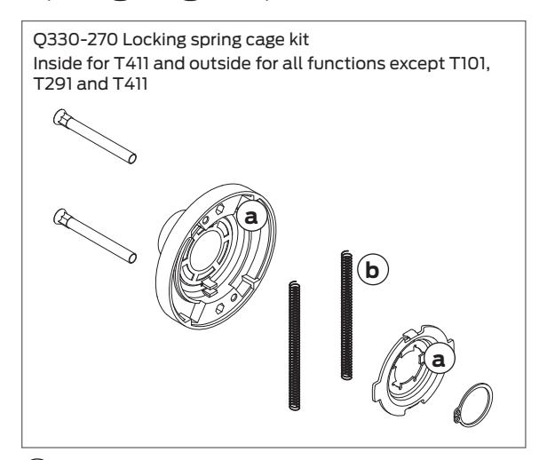
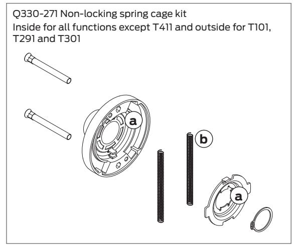
- a Apply light film of grease on surfaces with brush or equivalent.
- b Barrel or tumble with grease to acheive approximately .015-.040 film thickness
Levers
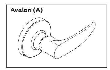
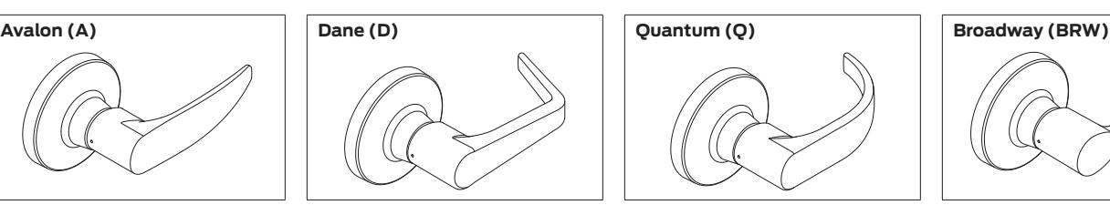
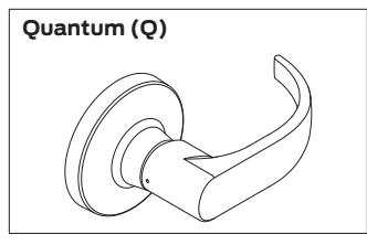
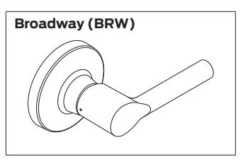
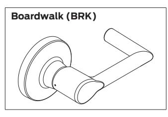
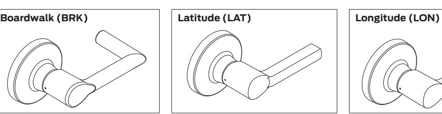
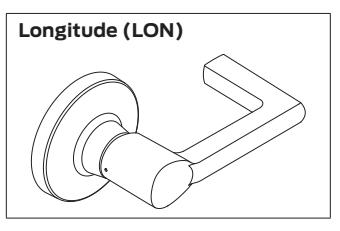
Closed Levers
| Style | Part number | Description |
|---|---|---|
| Avalon | 030740-000 | Outside |
| A30753-00A | Inside, w/set screw | |
| A31544-00A | Inside, w/set screw, 851/881 | |
| Boardwalk | Q330-430-BRK | Outside |
| A30753-00-BRK | Inside, w/set screw | |
| A31544-00-BRK | Inside, w/set screw, 851/881 | |
| Broadway | Q330-430-BRW | Outside |
| A30753-00-BRW | Inside, w/set screw | |
| A31544-00-BRW | Inside, w/set screw, 851/881 | |
| Dane | 030742-000 | Outside |
| A30753-00D | Inside, w/set screw | |
| A31544-00D | Inside, w/set screw, 851/881 | |
| Latitude | Q330-430-LAT | Outside |
| A30753-00-LAT | Inside, w/set screw | |
| A31544-00-LAT | Inside, w/set screw, 851/881 | |
| Longitude | Q330-430-LON | Outside |
| A30753-00-LON | Inside, w/set screw | |
| A31544-00-LON | Inside, w/set screw, 851/881 | |
| Quantum | 030744-000 | Outside |
| A30753-00Q | Inside, w/set screw | |
| A31544-00Q | Inside, w/set screw, 851/881 |
Open Levers
| Style | Part number | Description |
|---|---|---|
| Avalon | 030740-001 | Outside |
| 030929-001 | Corbin Russwin, Medeco, Yale unit | |
| 030996-001 | Sargent 6, 7 and 10 line, Yale | |
| A30753-01A | Inside, w/set screw | |
| Boardwalk | Q330-431-BRK | Outside |
| A30753-01-BRK | Inside, w/set screw | |
| Broadway | Q330-431-BRW | Outside |
| A30753-01-BRW | Inside, w/set screw | |
| Dane | 030742-001 | Outside |
| 030929-002 | Corbin Russwin, Medeco, Yale unit | |
| 030996-002 | Sargent 6, 7 and 10 line, Yale | |
| A30753-01D | Inside, w/set screw | |
| Latitude | Q330-431-LAT | Outside |
| A30753-01LAT | Inside, w/set screw | |
| Longitude | Q330-431-LON | Outside |
| A30753-01-LON | Inside, w/set screw | |
| Quantum | 030744-001 | Outside |
| 030929-003 | Corbin Russwin, Medeco, Yale unit | |
| 030996-003 | Sargent 6, 7and 10 line, Yale | |
| A30753-01Q | Inside, w/set screw |
FSIC Levers
| Style | Part number | Description |
|---|---|---|
| Avalon | 030926-001 | ASSA, Medeco, Yale |
| 030927-001 | Schlage | |
| 030928-001 | Corbin Russwin | |
| 030930-001 | Sargent | |
| Boardwalk | Q330-433-BRK | Schlage |
| Broadway | Q330-433-BRW | Schlage |
| Dane | 030926-002 | ASSA, Medeco, Yale |
| 030927-002 | Schlage | |
| 030928-002 | Corbin Russwin | |
| 030930-002 | Sargent | |
| Latitude | Q330-433-LAT | Schlage |
| Longitude | Q330-433-LON | Schlage |
| Quantum | 030926-003 | ASSA, Medeco, Yale |
| 030927-003 | Schlage | |
| 030928-003 | Corbin Russwin | |
| 030930-003 | Sargent |
SFIC Levers
| Style | Part number | Description |
|---|---|---|
| Avalon | 030740-002 | Lever, Avalon SFIC |
| Boardwalk | Q330-432-BRK | Lever, Boardwalk SFIC |
| Broadway | Q330-432-BRW | Lever, Broadway SFIC |
| Dane | 030742-002 | Lever, Dane SFIC |
| Latitude | Q330-432-LAT | Lever, Latitude SFIC |
| Longitude | Q330-432-LON | Lever, Longitude SFIC |
| Quantum | 030744-002 | Lever, Quantum SFIC |
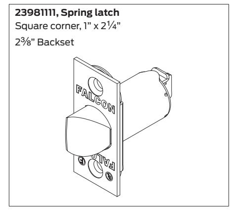
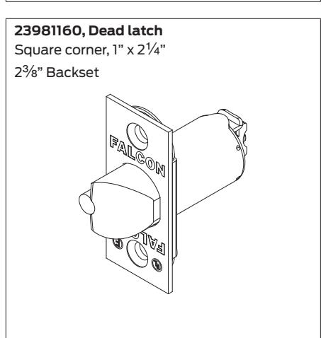
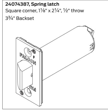
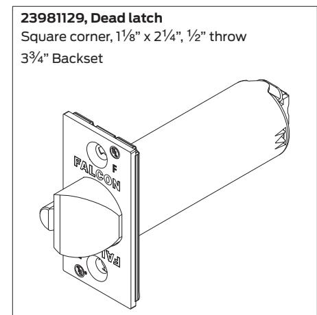
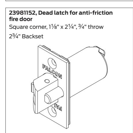
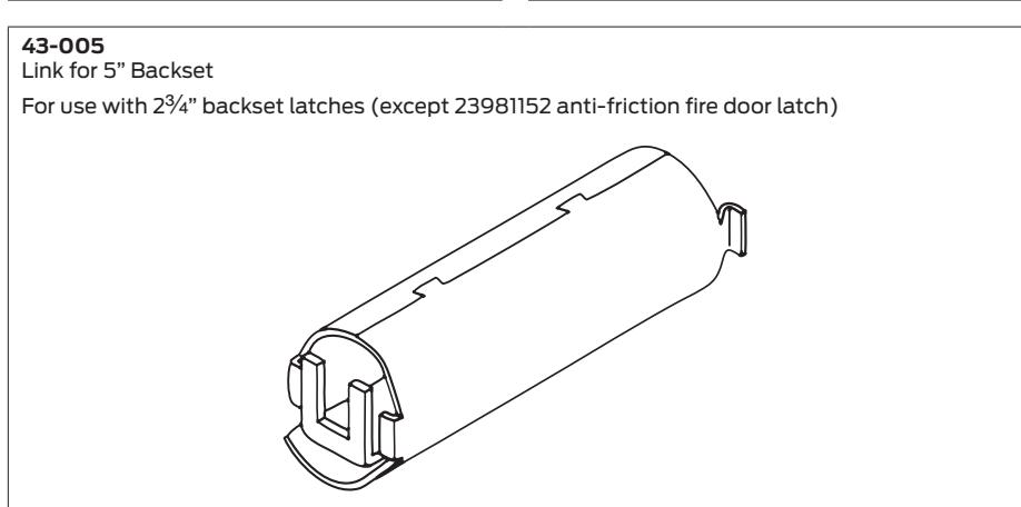
Latches
Finishes available: 606, 613, 630

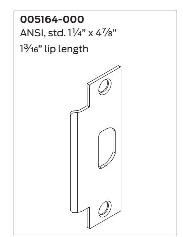
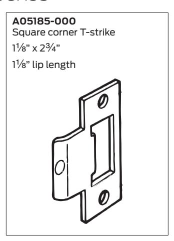
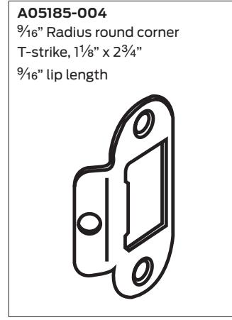
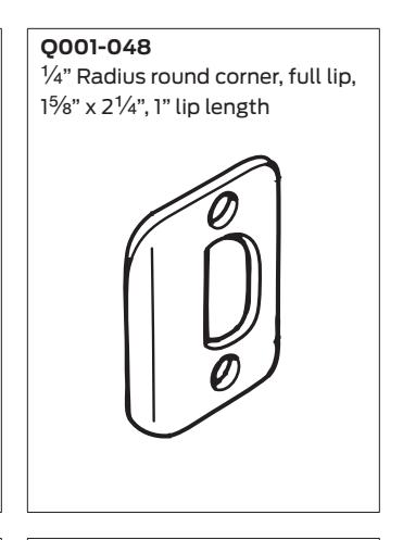
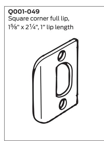
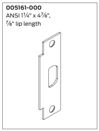
Strikes and dust boxes
Miscellaneous parts and accessories
Installation Instructions
T-Series
FALCON
Extra Heavy Duty Lockset
Installation Instructions
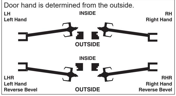
LHR Shown
IMPORTANT: This lock is non-handed. Lock is factory packed preadjusted for 1¾" (45 mm) thick doors. To adjust the lock for other door thickness, see "Adjust for door thickness (if necessary)". Spacers must be used for doors thinner than 13/4" (45 mm) thick. For functions T351, T381, T561 and T571, see "Timing instructions" for standard cylinder and IC core cylinder timing instructions.
For single dummy function (T12), go to step 7.
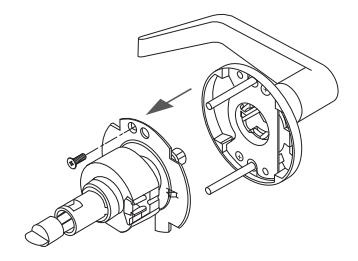
Outside trim assembly, IC cylinder
Spacer
See page 5 for explanation of Warnings, Cautions and Notices.
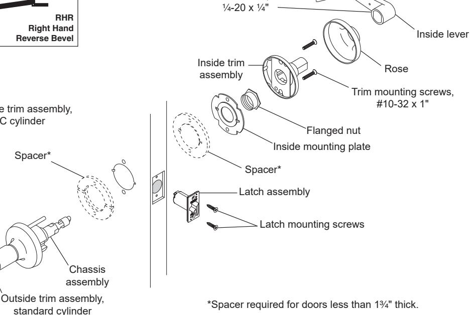
Set screw,

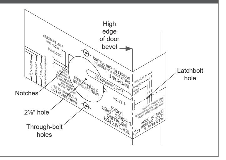
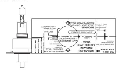
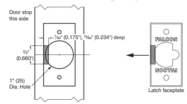
Mark the door.
- Fold the template as shown with the fold on the high edge of door bevel. Position template centerline on door height line (suggested height is 38" (97 cm) from finished floor).
-
Mark the door at positions indicated:
- One 2½" hole
- Two notches on sides of the 21/8" hole (notches must be horizontal)
- Two through-bolt holes
- · One latchbolt hole on the door edge.
- For single dummy function (T12), mark only the two through-bolt holes.
- If preparing a door with existing 21/8" hole, fold the template in half to mark the positions for two through-bolt holes. Be sure to mark positions for the notches.
- If steel frames are used, the latch centerline must be in line with the center of the strike preparation on the frame.
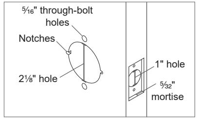
B Prepare the door.
- a. Drill a 21/8" (54 mm) hole through the door.
- b. Drill two 5/16" (8 mm) through-bolt holes.
Notice When drilling through the door, drill from both sides to avoid splintering wood.
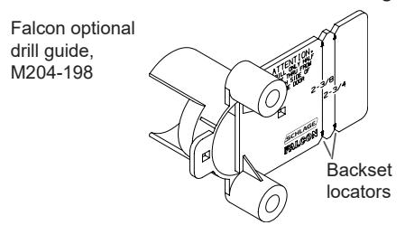
Note: A drill guide is recommended to ensure straight and level holes. If using the Falcon optional drill guide, make certain the correct backset locators are even with the door edge.
- c. Drill 1" hole on door edge to intersect with 21/8" hole.
-
Using the latch faceplate as a guide, trace outline and mortise the door edge so the latch will be flush with the door.
- ① If using ¾" projection latch additional preparation is required. See "3/4 inch projection latch preparation" for details.
- e. File two notches 5/32" (4 mm) x 5/32" (4 mm), 1/8" (3 mm) deep on both sides of the door.
For wood door jambs:
- Close the door and mark the position for the hole in the jamb using a strike locating tool or other pointed object.
- Open the door and drill a 1" (25 mm) hole, at least ¾" (19 mm) deep, in the jamb.
Adjust for door thickness (if necessary)
For 13/4" (45 mm) thick doors, skip to step 1.
If door is not (45 mm) thick, complete the following steps to adjust for door thickness.
A Remove outside trim retaining screw and slide the outside trim from the chassis
B Place template against retractor housing to locate door thickness mark.
-
C For doors greater than 13/4" (45 mm)
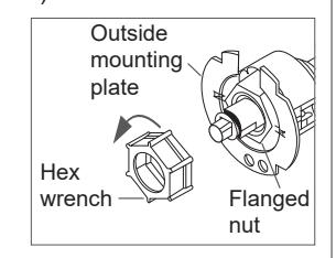
- Use hex wrench (included) to rotate the flanged nut counterclockwise.
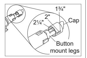
- Use the template to confirm accurate adjustment. Note: Three (3) full turns = 1/8" (3 mm).
- Pinch the button mount legs together and move the button cap to the desired position.
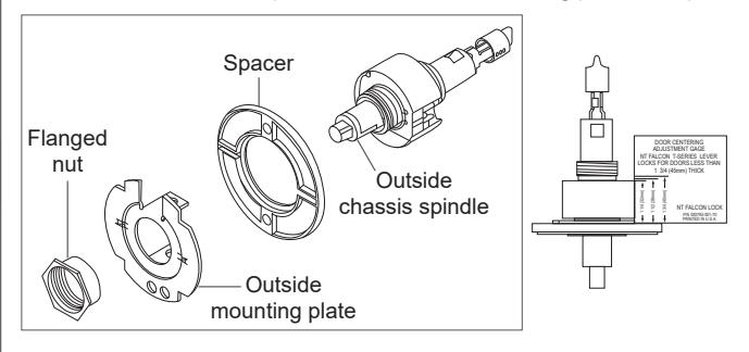
For doors less than 13/4" (45 mm)
- Use hex wrench (included) to remove the flanged nut.
- · Remove the outside mounting plate.
- · Place one spacer over the outside chassis spindle.
- · Reinstall outside mounting plate and flanged nut.
- Place the adjusting gauge against retractor housing and make any necessary additional adjustments to the flanged nut for proper door thickness.
- Install the second spacer with the inside mounting plate at step 3.
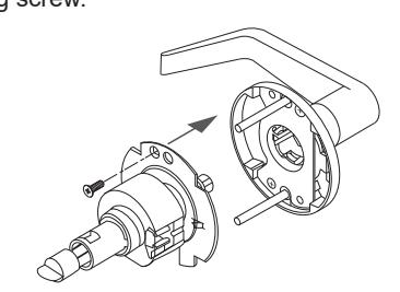
Slide the chassis on to the outside trim and secure the trim retaining screw.
Lock Installation
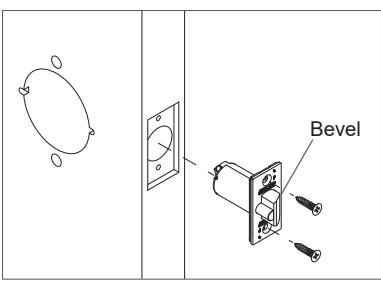
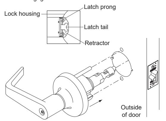
1 Install the latch.
The bevel must face toward the door stop.
2 Install chassis and outside trim assembly.
- 2a Unlock the lock.
- 2b Slide the chassis and outside trim assembly into the door. Make sure the lock housing engages the latch prongs and the retractor engages the latch tail.
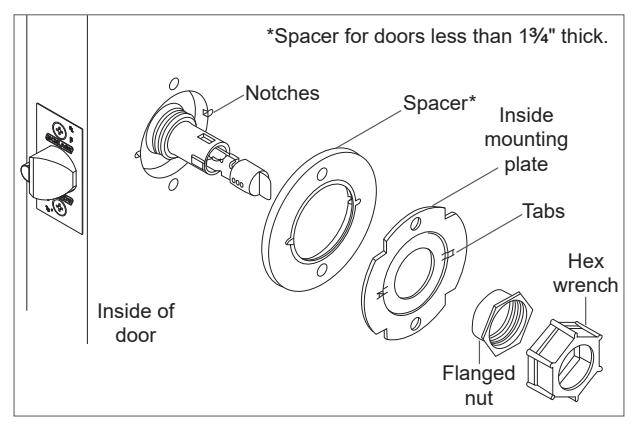
3 Install inside mounting plate.
- 3a Place inside mounting plate over chassis assembly. Make sure the tabs engage with the notches in the door. For doors less than 1 C\v " thick only, install the spacer.
- 3b Use the hex wrench (included) to tighten the flanged nut over the chassis.
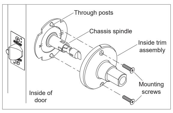
4 Install inside trim assembly.
Place the inside trim assembly over the chassis spindle. Through posts will engage the assembly on 1C\v" (45 mm) thick doors.
5 Install inside rose and lever.
5a Position the rose over the inside trim assembly. Make sure the rose detent engages the groove in the trim assembly.
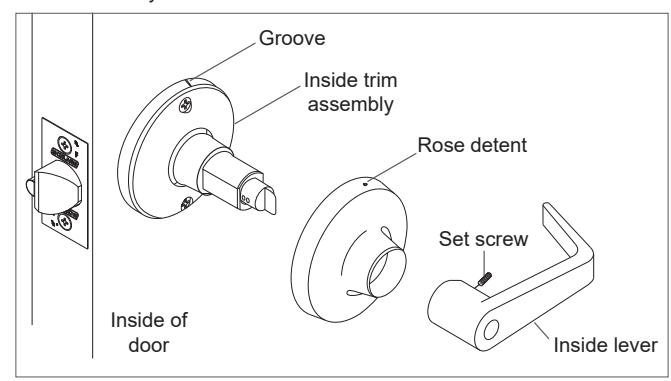
5b Install the lever and tighten the set screw with the hex key (included).
IMPORTANT! Test operation to be sure the latchbolt moves freely. DO NOT FORCE!
If the lock does not operate properly:
Remove the lock from the door and check door preparation (see "Installation Preparation") and door thickness adjustment (see "Adjust for door thickness (if necessary)).
For T351, T381, T561 and T571 only, check lock timing (see "Timing instructions" ).
Go back to step 2 to reinstall the lock.
6 Prepare the door jamb and install the strike.
When installing on a wood door jamb, complete steps 6a and 6b:
- 6a Center the strike opening over 1" (25 mm) hole in jamb. Then, trace the outline around the strike on the door jamb.
- 6b Mortise the door jamb to accommodate the strike dust box and the strike faceplate.
- 6c Insert the strike box if required and fasten the strike to the jamb with appropriate screws as shown.
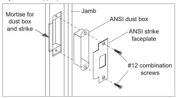
ANSI strike (standard)
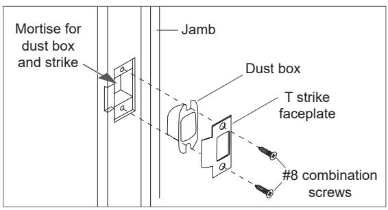
T strike (optional)
CAUTION
Deadlocking plunger of the latchbolt must not enter the opening in the strike plate. Plunger
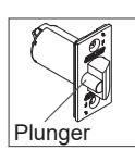
L Note: When the strike box is not used, the recess in the jamb must be a minimum of >\zn" (14 mm) deep to allow the latchbolt to extend to its full projection.
7 Install single dummy (T12) trim.
7a Using the template described at step A, locate and mark the center for two (2) mounting holes.
Wood doors: Drill two (2) pilot holes B\cx" (4 mm) x M\," (22 mm) deep for #12 wood screws.
Metal doors: Drill and tap two (2) holes for #12-24 machine screws.
7b Secure the inside trim/spindle assembly to the door with the appropriate screws.
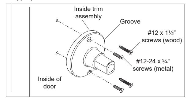
7c See step 5 for rose and lever installation.
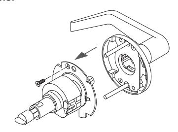
Remove keyed lever trim
Remove outside trim retaining screw and slide the outside trim from the chassis.
Remove cylinder levers except IC cylinder levers
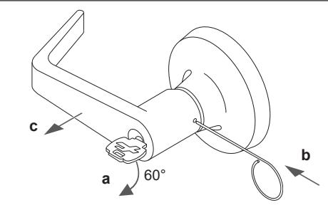
- a. Insert the key and rotate clockwise approximately 60°.
- b. Depress lever retainer with pin wrench.
- c. Slide lever off spindle.
Reinstall cylinder levers (except IC)
- Insert cylinder into spindle.
- Slide lever onto spindle and push on over the lever retainer.
- Insert key into cylinder and rotate clockwise approximately 60° and push lever over retainer.
- Pull on the lever to be sure the lever retainer is engaged.
4
Remove IC cylinder levers
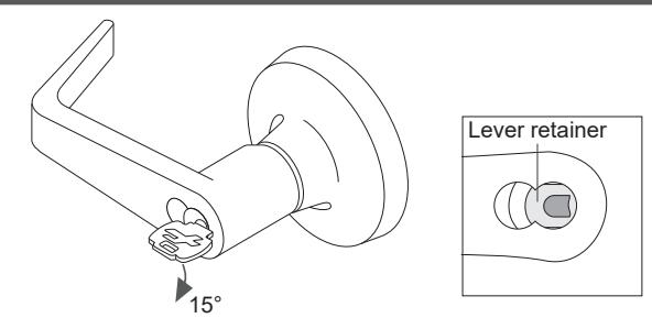
- Insert the control key and rotate clockwise 15°. Pull the key to remove the core.
- Insert flat screwdriver into the figure 8 cylinder opening and into the lever retainer.
- Depress lever retainer and slide lever off spindle.
Reinstall IC cylinder levers
- Slide lever onto spindle and push on over the lever retainer.
- Pull on the lever to be sure the retainer is engaged.
- Reinstall the IC core with the tailpiece pushed into the core.
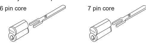
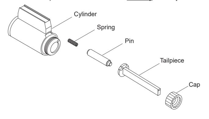
Interchangeable core tailpiece
Use the correct tailpiece with the IC core:
Six pin cores should use only the 6P tailpiece. Seven pin cores should use only the 7P tailpiece.
Tailpiece installation
The tailpiece must be installed correctly for proper lock function. All T-Series tailpieces should be installed vertically in the cylinder.
T381 tailpiece only
Standard and IC Core Long tailpiece Short tailpiece Long tailpiece Short tailpiece Outside standard cylinder assy Inside standard cylinder assy Clutch on outside
See "Tailpiece installation" for standard cylinder tailpiece installation.
See "Interchangeable core tailpiece" for IC core tailpiece installation.
3/4 inch projection latch preparation
Inside IC core assy
- On side of latch closest to door stop remove shaded area as shown. Use a standard rotary file C\," maximum.
- Test the latch for fit and function.
Outside IC core assy
• Secure the latch with two #8-32 screws (provided).
Warnings, Cautions and Notices
WARNING
Warnings indicate potentially hazardous conditions, which if not avoided or corrected, may cause death or serious injury.
CAUTION
Cautions indicate potentially hazardous conditions, which if not avoided or corrected, may cause minor or moderate injury. Cautions may also warn against unsafe practices.
NOTICE
Notices indicate a condition that may cause equipment or property damage only.
5
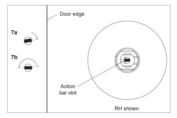
Timing instructions
For standard cylinder locks functions T351, T381, T561, T571
- L If cylinder and lever are installed, see "Remove keyed lever trim" for lever removal instructions.
- 7a Using a thin flat screwdriver, turn the action bar slot clockwise until it stops at approximately 2:00.
- 7b Turn the action bar slot counterclockwise to the 9:00 position. Note: there is no physical stop at this location.
- 7c With the key out, install the standard cylinder into the spindle.
- 7d See "Reinstall cylinder levers (except IC)" for lever reinstallation.
- 7e Test key for proper operation.
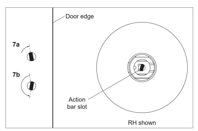
For IC core cylinder locks functions T351, T381, T561, T571
- L If the IC core is installed, see "Remove IC cylinder levers" for IC core removal instructions.
- 7a Using a thin flat screwdriver, turn the action bar slot clockwise until it stops at approximately 11:00.
- 7b Turn the action bar slot counterclockwise to the 7:00 position. Note: there is no physical stop at this location.
- 7c Using the control key, install the IC core cylinder into the lever and spindle.
- 7d Remove the control key
- 7e Test key for proper operation.

© Allegion 2018 030794 Rev. 03/18-g
Warranty
Falcon Door Hardware warrants its mechanical offering of locks, exit devices and door controls products manufactured to be free from defects in materials and workmanship for a period of TEN (10) YEARS from the date of manufacture with the exception of the products detailed in the table below. The terms and conditions of this new warranty apply to Falcon Door Hardware shipments made on or after November 1st, 2008.
This limited warranty does not cover products that (i) are not the proper size for the application; (ii) are not installed in accordance with Falcon's published installation instructions; (iii) are installed with improper or incorrect parts; (iv) have been modified, repaired, or altered in any way without the express written consent of Falcon; (v) are used for purposes which they are not designed or intended; (vi) are subjected to misuse, abuse, negligence, or accident; or (vii) are Grade 2 products used in educational facilities and student housing. The following costs and expenses are not covered by the provisions of this limited warranty; (i) labor costs for the removal and reinstallation of products; (ii) shipping and freight expenses required to return products to Falcon; (iii) normal maintenance; and (iv) economic losses. THE PROVISIONS OF THIS WARRANTY DO NOT APPLY TO FINISHES.
Falcon will replace the products that are found to be defective, provided said products are returned to Falcon within fifteen (15) days of defect.
FALCON SHALL IN NO EVENT BE LIABLE FOR ANY INCIDENTAL, CONSEQUENTIAL, INDIRECT, SPECIAL, OR PUNITIVE DAMAGES FOR ANY CLAIM WHETHER BASED ON CONTRACT, WARRANTY, TORT (INCLUDING, BUT NOT LIMITED TO, STRICT LIABILITY OR NEGLIGENCE), PATENT INFRINGEMENT, OR OTHERWISE, EVEN IF ADVISED OF THE POSSIBILITY OF SUCH DAMAGES.
This limited warranty replaces all other warranties, expressed or implied, and excludes any warranties of fitness for a particular purpose or merchantability. No agent, representative, dealer, or employee of Falcon has the authority to increase or alter the obligations of this limited warranty.
Note: Should the Product be considered a "consumer product" as may be covered by the Magnuson-Moss Federal Warranty Act, please be advised that: (1) Some states do not allow limitations on incidental or consequential damages or how long an implied warranty lasts, so that the above limitations may not fully apply; and (2) This warranty gives specific legal rights and a user may have rights which may vary from state to state.
| PRODUCT EXCEPTION | WARRANTY |
|---|---|
| OHC100A CONCEALED CLOSERS | 5 YEARS |
| 8200 AUTOMATIC OPERATOR | 2 YEARS |
| ELECTRONICS/ELECTRIFIED | 1 YEAR |
About Allegion
Allegion (NYSE: ALLE) is a global pioneer in safety and security, with leading brands like CISA®, Interflex®, LCN®, Schlage®, SimonsVoss® and Von Duprin®. Focusing on security around the door and adjacent areas, Allegion produces a range of solutions for homes, businesses, schools and other institutions. Allegion is a $2 billion company, with products sold in almost 130 countries.
For more, visit www.allegion.com .