Falcon T-Series Extra Heavy Duty Lever Lockset Installation Instructions – English 106829
Open the original PDF document
View PDF

030794
T-Series
FALCON
Extra Heavy Duty Lockset
Installation Instructions
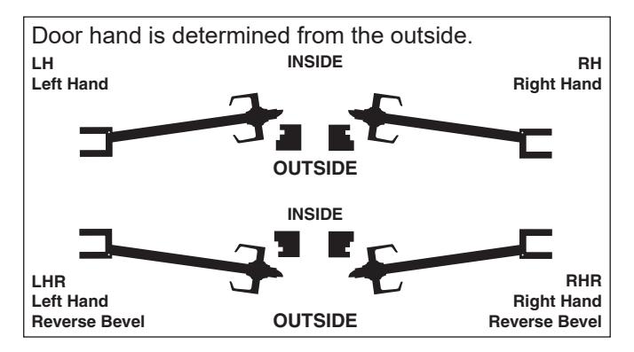
IMPORTANT: This lock is non-handed. Lock is factory packed preadjusted for 1¾" (45 mm) thick doors. To adjust the lock for other door thickness, see "Adjust for door thickness (if necessary)". Spacers must be used for doors thinner than 1¾" (45 mm) thick. For functions T351, T381, T561 and T571, see "Timing instructions" for standard cylinder and IC core cylinder timing instructions.
For single dummy function (T12), go to step 7.
See page 5 for explanation of Warnings, Cautions and Notices.
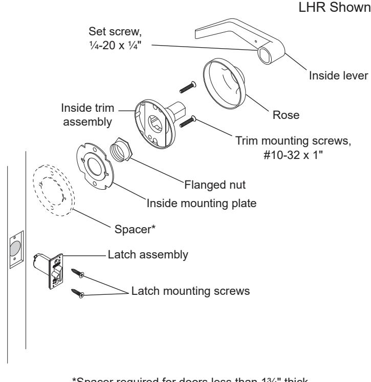
*Spacer required for doors less than 13/4" thick.
Installation Preparation
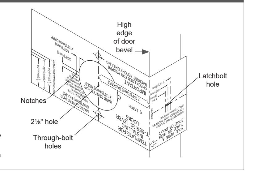
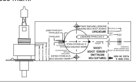
A Mark the door.
- Fold the template as shown with the fold on the high edge of door bevel. Position template centerline on door height line (suggested height is 38" (97 cm) from finished floor).
-
b. Mark the door at positions indicated:
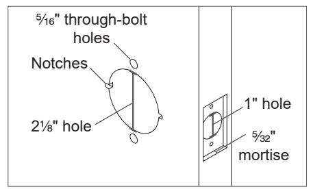
- · One 21/8" hole
- Two notches on sides of the 21/8" hole (notches must be horizontal)
- · Two through-bolt holes
- · One latchbolt hole on the door edge.
- Tor single dummy function (T12), mark only the two through-bolt holes.
- If preparing a door with existing 2½" hole, fold the template in half to mark the positions for two through-bolt holes. Be sure to mark positions for the notches.
- f) If steel frames are used, the latch centerline must be in line with the center of the strike preparation on the frame.
B Prepare the door.
- a. Drill a 21/8" (54 mm) hole through the door.
- b. Drill two 5/16" (8 mm) through-bolt holes.
Notice When drilling through the door, drill from both sides to avoid splintering wood.
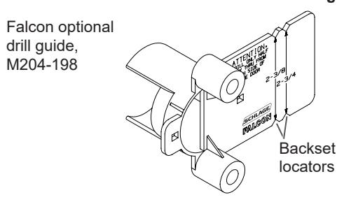
Note: A drill guide is recommended to ensure straight and level holes. If using the Falcon optional drill guide, make certain the correct backset locators are even with the door edge.
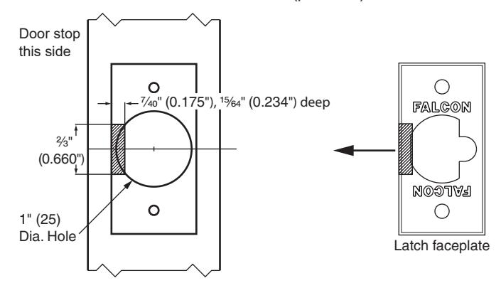
- c. Drill 1" hole on door edge to intersect with 21/8" hole.
-
d. Using the latch faceplate as a guide, trace outline and mortise the door edge so the latch will be flush with the door.
- ① If using ¾" projection latch additional preparation is required. See "3/4 inch projection latch preparation" for details.
- e. File two notches 5/32" (4 mm) x 5/32" (4 mm), 1/8" (3 mm) deep on both sides of the door.
For wood door jambs:
- Close the door and mark the position for the hole in the jamb using a strike locating tool or other pointed object.
- Open the door and drill a 1" (25 mm) hole, at least ¾" (19 mm) deep, in the jamb.
Adjust for door thickness (if necessary)
For 1¾" (45 mm) thick doors, skip to step 1.
If door is not 1% " (45 mm) thick, complete the following steps to adjust for door thickness.
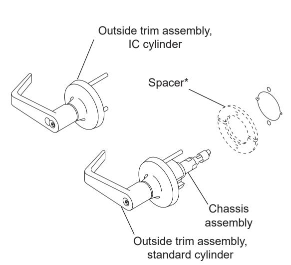
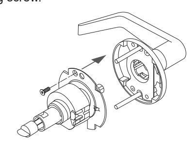
A Remove outside trim retaining screw and slide the outside trim from the chassis.
B Place template against retractor housing to locate door thickness mark.
-
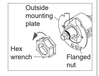
C For doors greater than 13/4" (45 mm)
- Use hex wrench (included) to rotate the flanged nut counterclockwise.
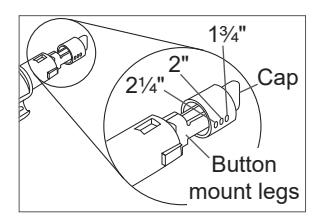
- Use the template to confirm accurate adjustment. Note: Three (3) full turns = 1/8" (3 mm).
- Pinch the button mount legs together and move the button cap to the desired position.
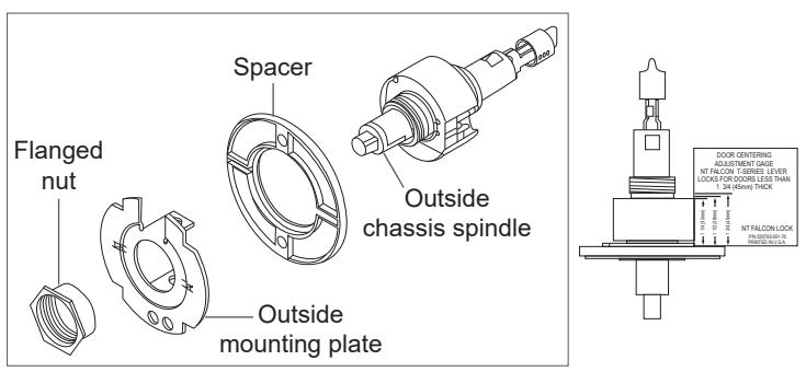
For doors less than 13/4" (45 mm)
- Use hex wrench (included) to remove the flanged nut.
- · Remove the outside mounting plate.
- · Place one spacer over the outside chassis spindle.
- · Reinstall outside mounting plate and flanged nut.
- Place the adjusting gauge against retractor housing and make any necessary additional adjustments to the flanged nut for proper door thickness.
- Install the second spacer with the inside mounting plate at step 3.
D Slide the chassis on to the outside trim and secure the trim retaining screw.
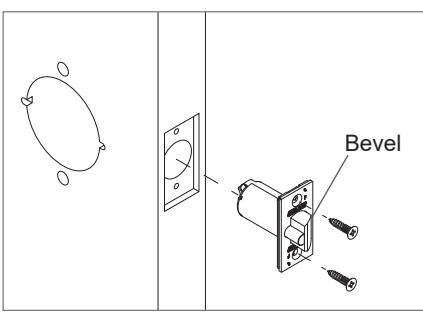
1 Install the latch.
The bevel must face toward the door stop.
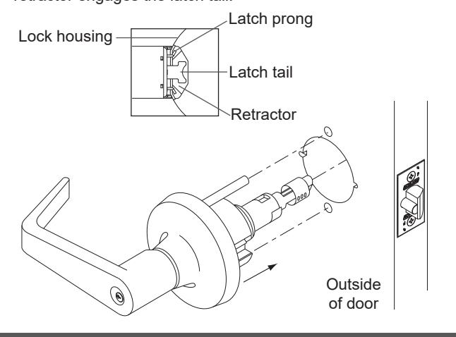
2 Install chassis and outside trim assembly.
- 2a Unlock the lock.
- 2b Slide the chassis and outside trim assembly into the door. Make sure the lock housing engages the latch prongs and the retractor engages the latch tail.
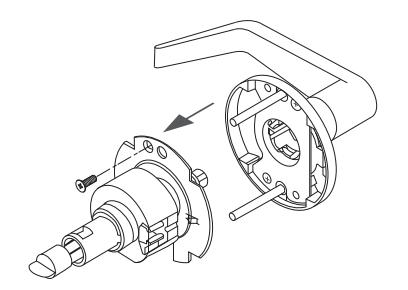
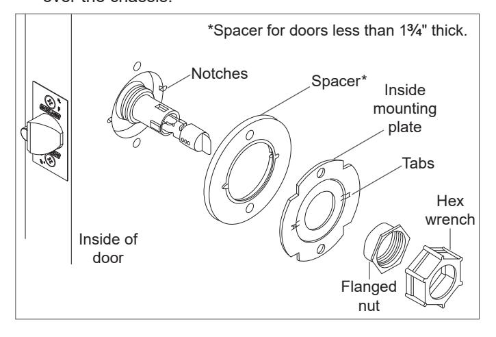
3 Install inside mounting plate.
- 3a Place inside mounting plate over chassis assembly. Make sure the tabs engage with the notches in the door. For doors less than 1 C\v " thick only, install the spacer.
- 3b Use the hex wrench (included) to tighten the flanged nut over the chassis.
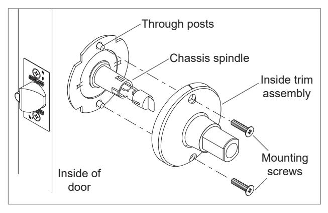
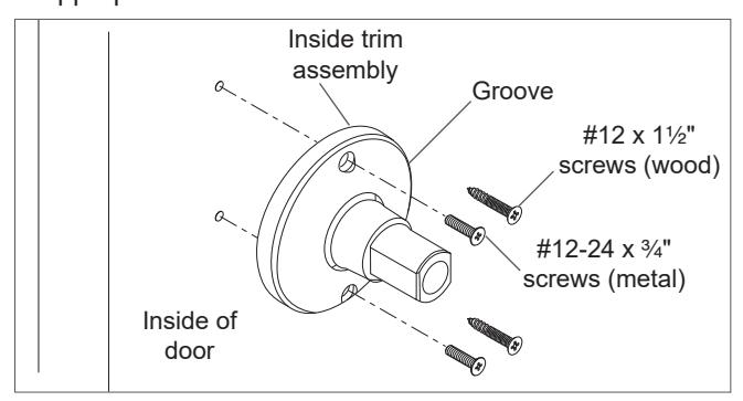
4 Install inside trim assembly.
Place the inside trim assembly over the chassis spindle. Through posts will engage the assembly on 1C\v" (45 mm) thick doors.
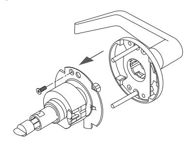
5 Install inside rose and lever.
5a Position the rose over the inside trim assembly. Make sure the rose detent engages the groove in the trim assembly.
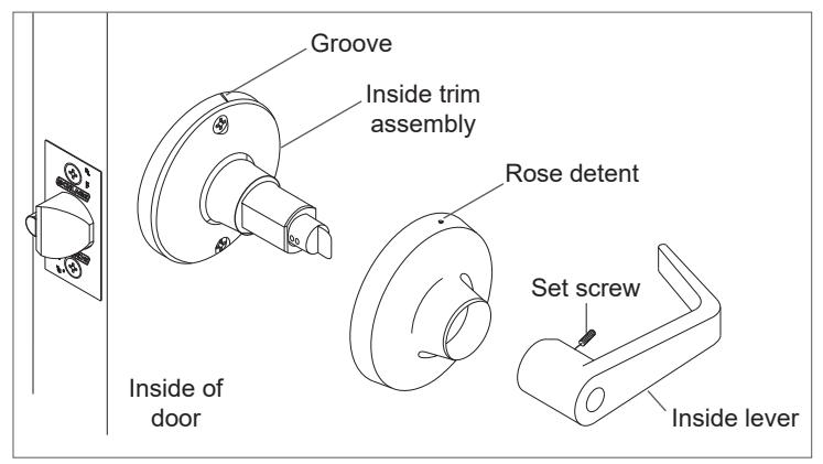
5b Install the lever and tighten the set screw with the hex key (included).
IMPORTANT! Test operation to be sure the latchbolt moves freely. DO NOT FORCE!
If the lock does not operate properly:
Remove the lock from the door and check door preparation (see "Installation Preparation") and door thickness adjustment (see "Adjust for door thickness (if necessary)).
For T351, T381, T561 and T571 only, check lock timing (see "Timing instructions" ).
Go back to step 2 to reinstall the lock.
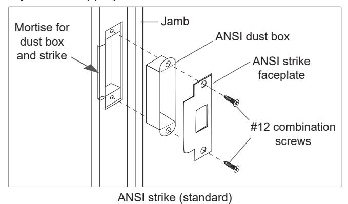
6 Prepare the door jamb and install the strike.
When installing on a wood door jamb, complete steps 6a and 6b:
- 6a Center the strike opening over 1" (25 mm) hole in jamb. Then, trace the outline around the strike on the door jamb.
- 6b Mortise the door jamb to accommodate the strike dust box and the strike faceplate.
- 6c Insert the strike box if required and fasten the strike to the jamb with appropriate screws as shown.
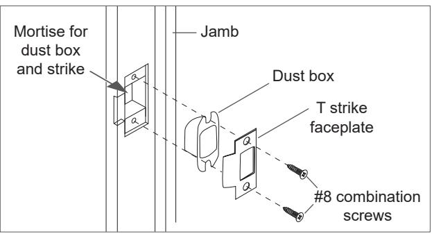
T strike (optional)
CAUTION
Deadlocking plunger of the latchbolt must not enter the opening in the strike plate. Plunger
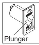
L Note: When the strike box is not used, the recess in the jamb must be a minimum of >\zn" (14 mm) deep to allow the latchbolt to extend to its full projection.
7 Install single dummy (T12) trim.
7a Using the template described at step A, locate and mark the center for two (2) mounting holes.
Wood doors: Drill two (2) pilot holes B\cx" (4 mm) x M\," (22 mm) deep for #12 wood screws.
Metal doors: Drill and tap two (2) holes for #12-24 machine screws.
7b Secure the inside trim/spindle assembly to the door with the appropriate screws.
7c See step 5 for rose and lever installation.
Remove keyed lever trim
Remove outside trim retaining screw and slide the outside trim from the chassis.
Remove cylinder levers except IC cylinder levers
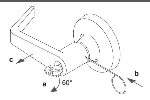
- a. Insert the key and rotate clockwise approximately 60°.
- b. Depress lever retainer with pin wrench.
- c. Slide lever off spindle.
Reinstall cylinder levers (except IC)
- Insert cylinder into spindle.
- Slide lever onto spindle and push on over the lever retainer.
- Insert key into cylinder and rotate clockwise approximately 60° and push lever over retainer.
- Pull on the lever to be sure the lever retainer is engaged.
Remove IC cylinder levers
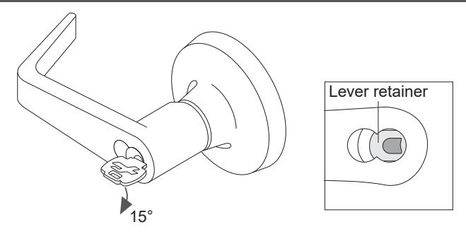
- Insert the control key and rotate clockwise 15°. Pull the key to remove the core.
- Insert flat screwdriver into the figure 8 cylinder opening and into the lever retainer.
- Depress lever retainer and slide lever off spindle.
Reinstall IC cylinder levers
- Slide lever onto spindle and push on over the lever retainer.
- Pull on the lever to be sure the retainer is engaged.
- Reinstall the IC core with the tailpiece pushed into the core.
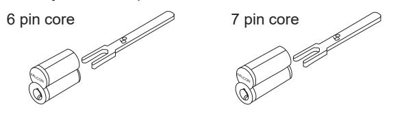
Interchangeable core tailpiece
Use the correct tailpiece with the IC core:
Six pin cores should use only the 6P tailpiece. Seven pin cores should use only the 7P tailpiece.
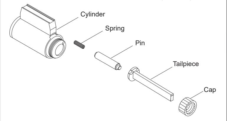
Tailpiece installation
The tailpiece must be installed correctly for proper lock function. All T-Series tailpieces should be installed vertically in the cylinder.
T381 tailpiece only
Standard and IC Core
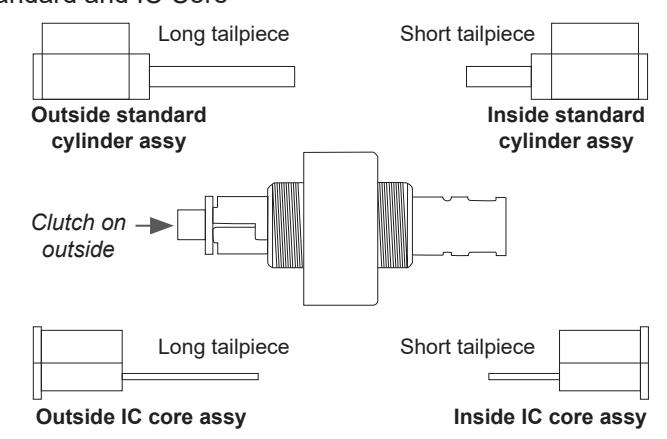
See "Tailpiece installation" for standard cylinder tailpiece installation.
See "Interchangeable core tailpiece" for IC core tailpiece installation.
3/4 inch projection latch preparation
- On side of latch closest to door stop remove shaded area as shown. Use a standard rotary file C\," maximum.
- Test the latch for fit and function.
- Secure the latch with two #8-32 screws (provided).
Warnings, Cautions and Notices
WARNING
Warnings indicate potentially hazardous conditions, which if not avoided or corrected, may cause death or serious injury.
CAUTION
Cautions indicate potentially hazardous conditions, which if not avoided or corrected, may cause minor or moderate injury. Cautions may also warn against unsafe practices.
NOTICE
Notices indicate a condition that may cause equipment or property damage only.
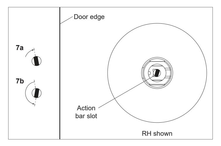
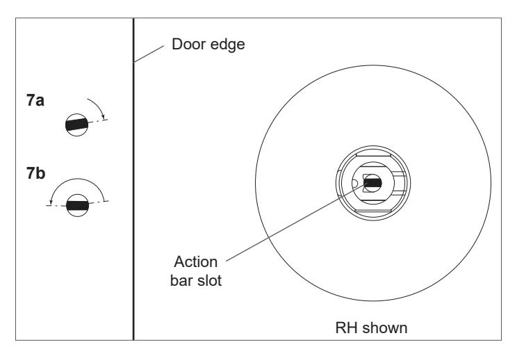
Timing instructions
For standard cylinder locks functions T351, T381, T561, T571
- L If cylinder and lever are installed, see "Remove keyed lever trim" for lever removal instructions.
- 7a Using a thin flat screwdriver, turn the action bar slot clockwise until it stops at approximately 2:00.
- 7b Turn the action bar slot counterclockwise to the 9:00 position. Note: there is no physical stop at this location.
- 7c With the key out, install the standard cylinder into the spindle.
- 7d See "Reinstall cylinder levers (except IC)" for lever reinstallation.
- 7e Test key for proper operation.
For IC core cylinder locks functions T351, T381, T561, T571
- L If the IC core is installed, see "Remove IC cylinder levers" for IC core removal instructions.
- 7a Using a thin flat screwdriver, turn the action bar slot clockwise until it stops at approximately 11:00.
- 7b Turn the action bar slot counterclockwise to the 7:00 position. Note: there is no physical stop at this location.
- 7c Using the control key, install the IC core cylinder into the lever and spindle.
- 7d Remove the control key
- 7e Test key for proper operation.