Falcon S-Series and X-Series Interchangeable Core Installation Instructions – English 106803
Open the original PDF document
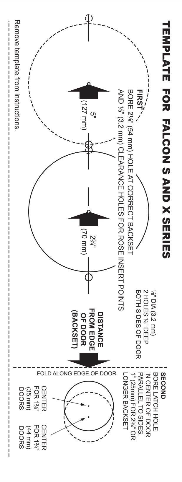
View PDFSORE LATCH HOLE ARALLEL TO SIDES. 8" (22mm) FOR 2%" BACKSET " (25mm) FOR 2%" CENTER FOR 136" (35 mm) DOORS FOLD ALONG EDGE OF DOOR 1/8" DIA (3.2 mm) 2 HOLES 1/8" DEEP BOTH SIDES OF DOOR SERIES AND X BACKSET R ROSE IN CT B FOR FALCON HOLE AT LEARANCE FOR mm) H m) CLI FEMPLATE FIRST BORE AND 1%

FALCON ® S-Series & X-Series Interchangeable Core
MARK DOOR
Recommended template instructions must be followed to assure proper functioning.
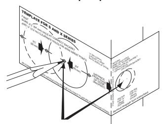
Mark centers for latch hole, side hole and rose insert points on both sides of door.
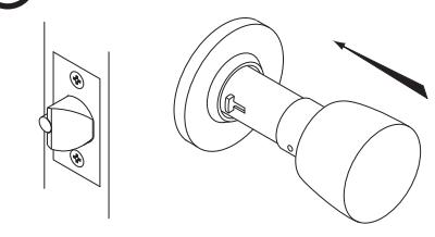
REMOVE INSIDE TRIM
Depress knob catch to remove knob. If cylinder knob, see reverse side of sheet.
Remove rose by unscrewing collar.
Remove template from instructions.
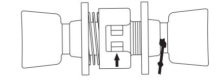
BORE 3 HOLES
A. Bore side hole from both sides of door.
B. Bore latch hole.
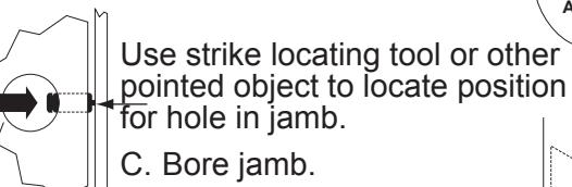
NOTE: A minimum 3/4" deep hole must be bored in frame behind opening in strike for proper function of latch bolt.
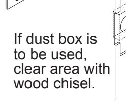
Outline latch face and strike as illustrated and chisel out to proper depth.
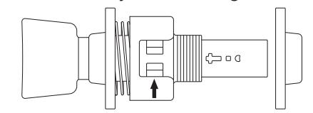
ADJUST FOR DOOR THICKNESS
Hold lock against edge of door. Adjust outer rose collar so door center mark on lock housing is in center of door.
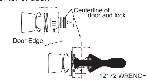
ALTERNATE METHOD
Wrench can be used to adjust lock for door thickness by holding tip of wrench against rose insert and turning rose collar until desired arrow on wrench lines up with arrow on lock case.
INSTALL LATCH AND STRIKE
Install latch. Be sure beveled side of latch bolt is facing the door frame.
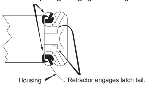
ENGAGE LOCK WITH LATCH (6)
Both latch prongs engage housing.
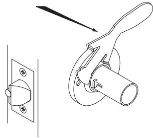
7 SECURE LOCK TO DOOR
Replace inside rose and collar. Use spanner wrench to turn collar clockwise and tighten firmly.
8 INSTALL KNOB
Place knob on spindle, slide to knob catch, depress knob catch and push knob until catch engages slot in knob. If cylinder knob, see reverse side of sheet.
A. TO REMOVE IC KNOB
INTERCHANGEABLE CORE MUST BE REMOVED BEFORE KNOB CAN BE REMOVED.
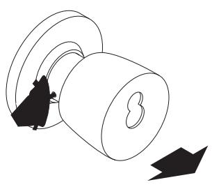
Pull tailpiece assembly towards open end of knob as far as it will go. Depress knob catch and pull off knob.
To change hand of lock, rotate knob and spindle cap 180° before replacing knob.
C. TO INSTALL IC CORE
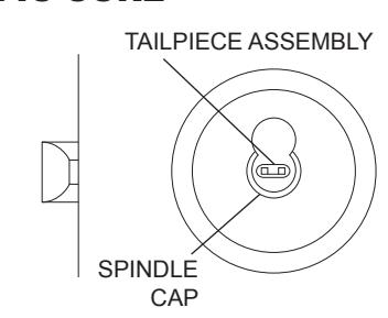
Push tailpiece assembly all the way into spindle. Tailpiece legs must be in horizontal position before Interchangeable Core can be installed.
B. TO INSTALL IC KNOB
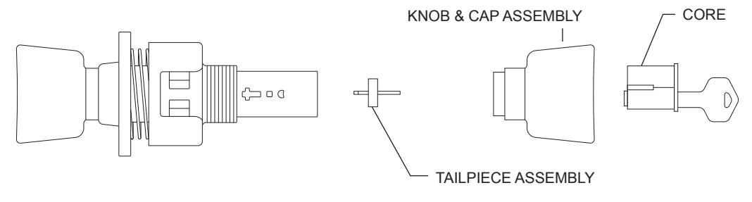
With tailpiece assembly in end of spindle (not engaged in knob catch). Slip knob over spindle, with smaller hole in knob face up. Slip shank of knob up to knob catch. Depress knob catch and push knob until knob catch engages slot in knob.

© Allegion 2014 Printed in U.S.A. 002291-000-70 Rev. 10/14-d
BEGINNING SHEET FOLDED SHEET
| Additional Notes: | |
|---|---|
| 1. None | |
| Revision History | Revision Description: | |||||||||
|---|---|---|---|---|---|---|---|---|---|---|
| А | В | С | D | Е | F | D > Revised artwork | ||||
| FAL | 0790 | 6683 | ||||||||
| Material | Edited By | Approved By | EC Number | Release Date | ||||||
| White Paper | J. Ellis | M. Roberts | xxxxx | 10/14 | ||||||
| Notes |
Notes
1. printed both sides |
Title | ||||||||
| 2. printed black | Sheet Instruction, S & X, IC | |||||||||
| 3. tolerance ± .13 | Creation Date | Number | Revision | |||||||
| printed in country may vary barcode shows after folding | 10-22-14 | 002291-000-70 | D | |||||||
| 5. Darcode shows after folding |
Created By
J. Ellis |
Activity
3899 Hancock Expwy |
||||||||
| Software: InDesign CS6 | Security, CO 80911 | © Allegion 2014 | ||||||||