Falcon S-Series and X-Series Falcon Locks Installation Instructions – English 106802
Open the original PDF document
View PDF

MARK DOOR
Recommended template instructions must be followed to assure proper functioning. (See attached template).
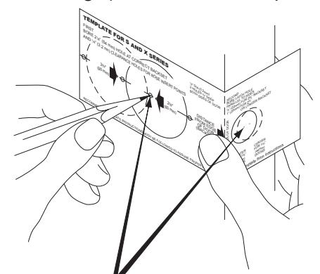
Mark centers for latch hole, side hole and rose insert points on both sides of door.
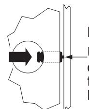
BORE 3 HOLES
A. Bore side hole from both sides of door.
B. Bore latch hole. Use strike locating tool
or other pointed object to locate position for hole in jamb.
C. Bore jamb.
NOTE: A minimum 3/4" deep hole must be bored in frame behind opening in strike for proper function of latch bolt.
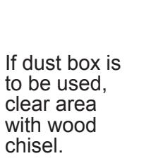
Outline latch face and strike as illustrated and chisel out to proper depth.

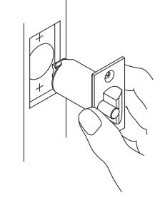
INSTALL LATCH AND STRIKE
chisel.
Install latch. Be sure beveled side of latch bolt is facing the door frame.

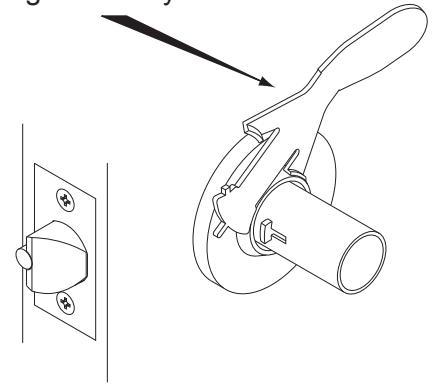
REMOVE INSIDE TRIM
Depress knob catch to remove knob.
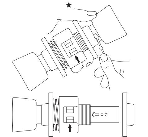
Remove rose by unscrewing collar ★ If Cylinder knob, see reverse side.

Hold lock against edge of door. Adjust outer rose collar so door center mark on lock housing is in center of door.
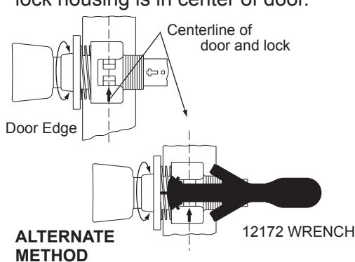
Wrench can be used to adjust lock for door thickness by holding tip of wrench against rose insert and turning rose collar until desired arrow on wrench lines up with arrow on lock case.

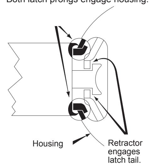
ENGAGE LOCK WITH LATCH
Both latch prongs engage housing.

SECURE LOCK TO DOOR
Replace inside rose and collar and using spanner wrench turn collar clockwise and tighten firmly.

INSTALL KNOB
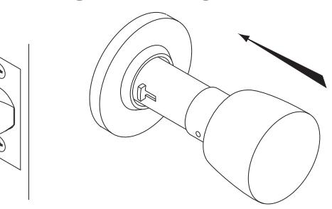
Place knob on spindle, slide to knob catch, depress knob catch and push knob until catch engages slot in knob. ★ If cylinder knob, see reverse side.
FOLD ALONG EDGE OF DOOR
) SIDES. )R 23%" BACKSET R 234" R LONGER BACKSET
CORRECT BACKSET
SERIES
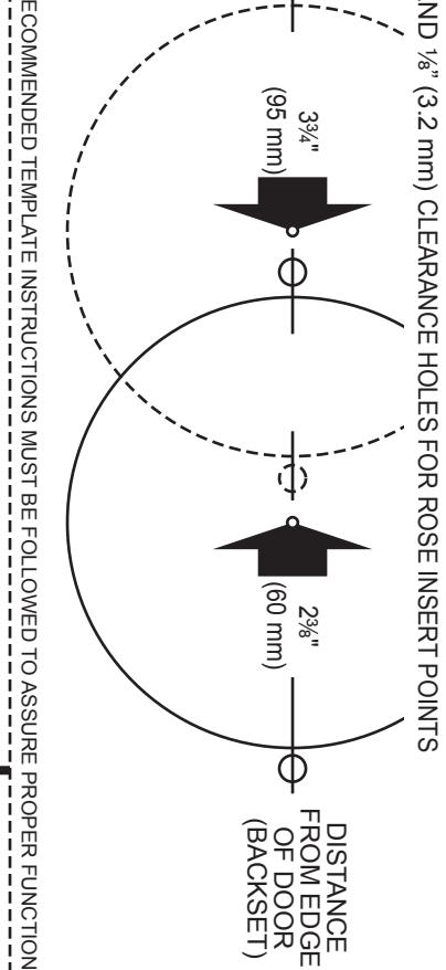
TEMPLATE FOR S AND X SERIES RECOMMENDED TEMPLATE INSTRUCTIONS MUST BE FOLLOWED TO ASSURE PROPER FUNCTIONING. DISTANCE FROM EDGE OF DOOR (BACKSET) 5" (127 mm) 2 ³⁄₄" (70 mm) FOLD ALONG EDGE OF DOOR SECOND BORE LATCH HOLE IN CENTER OF DOOR PARALLEL TO SIDES. 1" (25 mm) FOR 2³⁄₄" OR LONGER BACKSET CENTER FOR 1³⁄₈" (35 mm) DOORS CENTER FOR 1³⁄₄" (44 mm) DOORS FIRST BORE 2¹⁄₈" (54 mm) HOLE AT CORRECT BACKSET AND ¹⁄₈" (3.2 mm) CLEARANCE HOLES FOR ROSE INSERT POINTS LITHO IN U.S.A. ¹⁄₈" DIA (3.2 mm) 2 HOLES ¹⁄₈" DEEP BOTH SIDES OF DOOR
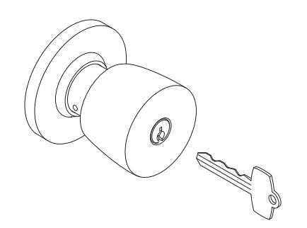
INSTRUCTIONS FOR REMOVAL OF AND REASSEMBLY OF CYLINDER KNOB
Cylinder knob should be installed as shown. (key notches up)
If necessary to change hand of lock so that cylinder will be right side up, use the following instructions:
TO REMOVE CYLINDER KNOB
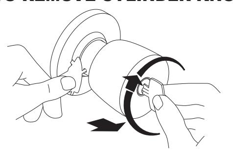
Assembly not installed in door: Rotate key ¹⁄₄ turn clockwise, depress knob catch and pull off knob. Rotate housing 180° and reinstall cylinder knob.
Assembly installed in door: Rotate key ¹⁄₄ turn clockwise, depress knob catch and pull off knob. Rotate knob 180° and reinstall cylinder knob.
HOW TO INSTALL S SERIES AND X SERIES FALCON LOCKS
HOW TO INSTALL S SERIES AND X SERIES FALCON LOCKS
TO INSTALL CYLINDER KNOB
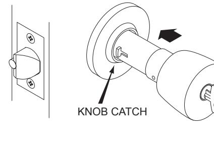
With key in cylinder, align hole in knob cap with knob catch and slip knob over spindle up to knob catch.
STEP ONE STEP TWO
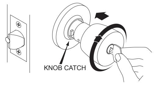
With knob against knob catch, and cylinder tailpiece engaged with key spindle, hold knob, rotate key ¹⁄₄ turn clockwise. Depress knob catch and push knob until catch engages slot in knob.


© Allegion 2014 Printed in U.S.A. 002290-000-70 Rev. 10/14-d
FRONT 4.000 FOLDED SHEET
BEGINNING SHEET
| Additional Notes: | ||
|---|---|---|
| 1. None | ||
| Revision History | Revision Description: | |||||||||
|---|---|---|---|---|---|---|---|---|---|---|
| А | В | С | D | Е | F | D > Revised artwork | ||||
| 4526 | 0790 | 6683 | ||||||||
| Material | Edited By | Approved By | EC Number | Release Date | ||||||
| White Paper | J. Ellis | M. Roberts | xxxxx | 10/14 | ||||||
| Notes | Notes | Title | ||||||||
|
Sheet Instruction, S & X | |||||||||
| 3. tolerance ± .13 | Creation Date | Number | Revision | |||||||
|
10-22-14 | 002290-000-70 | D | |||||||
|
Created By
J. Ellis |
Activity
3899 Hancock Expwy Security, CO 80911 |
• | ||||||||
| Software: InDesign CS6 | Allegion 2014 | |||||||||