Falcon Reversing Hand of M-Series Mortise Locks Installation Instructions – English 106804
Open the original PDF document
View PDF


INSTRUCTIONS FOR REVERSING HAND OF M-SERIES MORTISE LOCKS
If it is necessary to reverse the hand of a Falcon M-Series Mortise lock, it is quickly and easily accomplished by the following steps.
NOTE:
If the lock has a dead bolt, it must be in the retracted position when reversing hand.
1. REMOVE COVER
Remove the 4 Cover fastening Screws and slowly lift off cover from case.
2. REVERSE LATCH BOLT ASSEMBLY
- A . Lift out Cylinder Retract Lever, if included.
- B . Lift out Upper Retract Arm, if included.
- C . Compress Latch Bolt Spring toward Face Plate to clear Latch Bolt Guide seat. Lift out and invert Latch Bolt Assembly. Place Latch Bolt Spring into Latch Bolt Guide seat.
NOTE:
Lower Retract Arm must be between Latch Bolt Foot & Latch Bolt Guide.
3. REVERSE HUBS
NOTE:
Hub reversing is required only on locks that contain two differently shaped hubs.
A . To reverse, pull Coupling toward rear of case.
B . Lift out both Hubs together, invert as an assembly and replace.
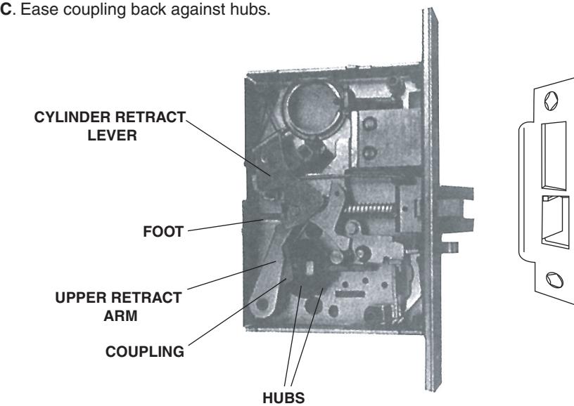
4. REASSEMBLE RETRACT ARM AND LEVER
- A. Replace Upper Retract Arm so that arm fits into space between Latch Bolt Foot and Coupling.
- B. Replace Cylinder Retract Lever so that it straddles the Dead Bolt Pin.
- C. Replace Cover guiding "T" Turn Hub into cover hole. Depress Latch Bolt to clear Foot.
NOTE:
A phillips head screw driver inserted thru cover into "T" turn hub will retain hub and Cylinder Retract Lever in proper location while replacing cover.
D. Replace Cover fastening Screws.
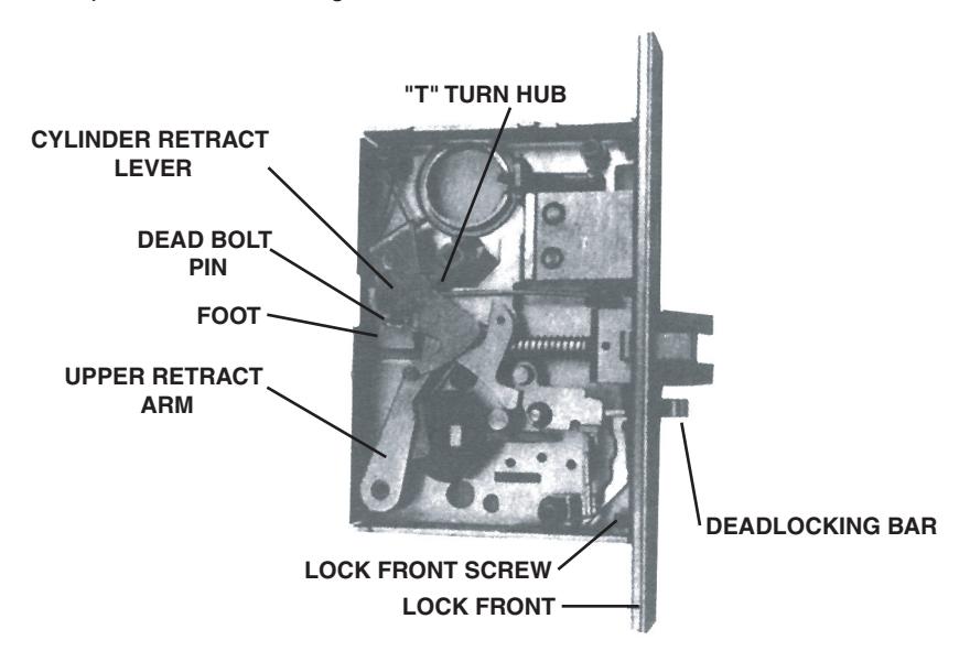
5. REVERSE DEADLOCKING BAR
- A. If the locking unit contains an auxillary Deadlocking Bar, remove Face Plate Remove Deadlocking Bar, reverse and replace back into assembly.
- B. Replace Face Plate.
NOTE:
The concave face of Deadlocking Bar must be on same side of door as the beveled face on the Latch Bolt. If this condition is not met, the Latch Bolt will be blocked from being able to be depressed as it comes into contact with the strike.
6. ADJUST BEVEL
Set Bevel of lock front to match door Bevel and securely tighten screws.
7. STRIKE
Replace Strike with Proper Hand condition if necessary.


BEGINNING SHEET
| FRONT | |
|---|---|
| 4.250 | |
| FOLDED SHEET | |
_____ 5.500 <del>_____</del>
| Additional Notes: | |
|---|---|
| 1. None | |
| Revision History | Revision Description: | |||||||||
|---|---|---|---|---|---|---|---|---|---|---|
| А | В | С | D | E | F | D > Revised artwork | ||||
| 5598 | 0790 | 6683 | ] | |||||||
| Material | Material White Paper | Edited By | Approved By | EC Number | Release Date | |||||
| J. Ellis | M. Roberts | xxxxx | 10/14 | |||||||
| 1 ' | Notes 1. printed both sides 2. printed black | Instruction Sheet, Reversing Hand of M-Series Mortise Locks | ||||||||
| 2. printed black 3. tolerance ± .13 4. printed in country may vary |
Creation Date
10-22-14 |
Number 002302-001-70 |
Revision
D |
|||||||
|
Created By
J. Ellis |
Activity
3899 Hancock Expwy |
|||||||||
| Software: InDesign CS6 | Security, CO 80911 | Allegion 2014 | ||||||||