Falcon RW-Series Retrofit Lever Trim Mounting Installation Instructions – English 106827
Open the original PDF document
View PDF

030388-000-70
RW Series Retrofit Lever Trim
FALCON ®
Installation Instructions
Mounting and Rehanding
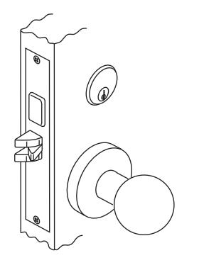
STEP ONE:
Remove all existing trim from door, including cylinder if one is installed.
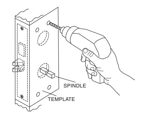
STEP TWO:
Insert inner and outer spindles into lock hubs. NOTE: Because of various hub sizes, be sure spindles fit properly. Place the enclosed template over the spindle. Align with door edge and mark the four (4) thru-bolt hole locations. This should be done to both sides of the door. Drill the four (4) holes halfway through from each side of door.
IMPORTANT: It may be necessary to enlarge the trim hole due to varying door preps. Falcon retrofit trim requires both sides to be 11/8" diameter minimum to clear trim mechanism.
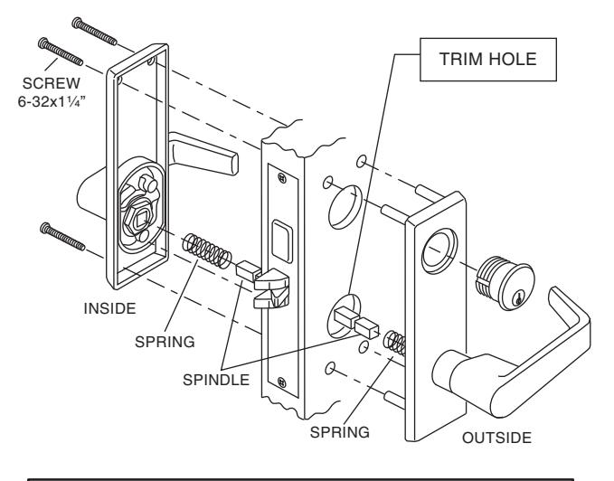
STEP THREE: Before mounting the trim, be sure to insert spindle springs into each lever. With spindle in outer hub, place outer trim over spindle with posts going into thruholes. Place inside trim over spindle and install the four (4) mounting screws. Before screws are tightened, check to see that both levers are operating properly. If reinstalling the cylinder, determine if a blocking ring is required. Tighten set screw then check cylinder for proper function. Tighten the four (4) trim mounting screws.
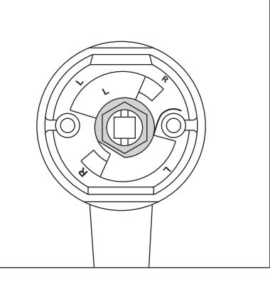
RE-HANDING INSTRUCTIONS FOR FALCON RW SERIES LOCK TRIM Example shown is a right hand being changed to a left hand Reverse sequence to change from left to right hand VIEWED FROM OUTSIDE
Note: Inside trim is always opposite the outside trim LH/LHR RH/RHR
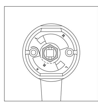
1. Holding lever as shown, bend tab of lockwasher back flat. Remove nut.
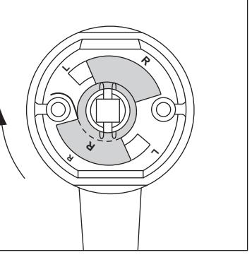
2. Holding lever securely, rotate rose assembly clockwise slightly, and remove plate and lockwasher.
R
R
L
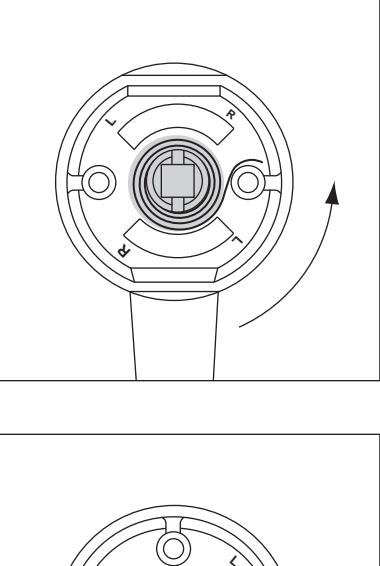
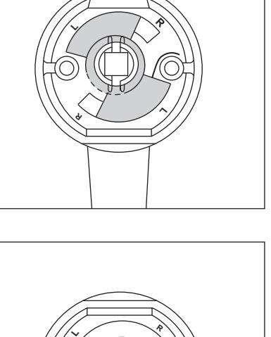
5. Holding lever securely, rotate rose assembly counterclockwise slightly past 90 deg.
4. Remove spring and reinstall with spring hook on opposite
side of post.
R
L
L
3. Using caution, allow rose assembly to rotate counterclockwise to relieve spring tension.
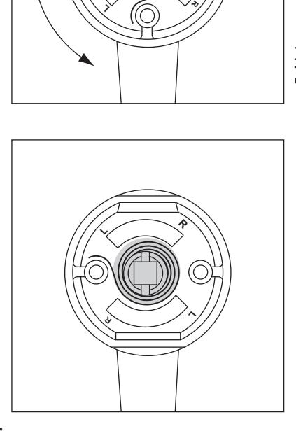
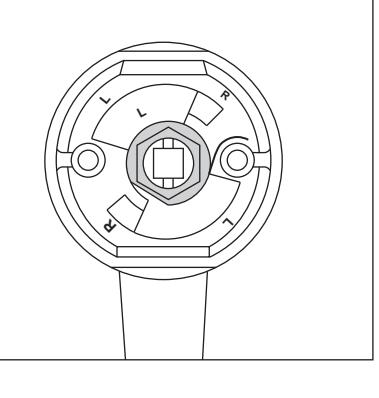
7. Reinstall lockwasher and nut. Tighten nut and then back off slightly until rose assembly rotates freely under plate. Bend up one tab of lockwasher against nut.
6. Reinstall plate with "L" side up and in line with "L" on rose assembly.

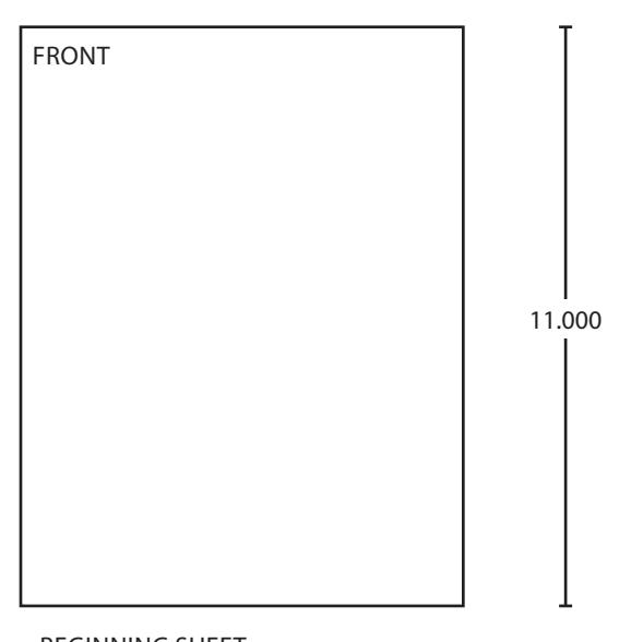
FRONT 3.670
BEGINNING SHEET FOLDED SHEET
| Additional Notes: | |
|---|---|
| 1. None | |
| Revision History | Revision Description: | ||||||||||
|---|---|---|---|---|---|---|---|---|---|---|---|
| А | В | С | D | Е | F | D > Revised artwork | rised artwork | ||||
| 4955-255 | 0790 | 6683 | |||||||||
| Material White Paper | Edited By | Approved By | EC Number | Release Date | |||||||
| J. Ellis | M. Roberts | xxxxx | 10/14 | ||||||||
| Notes | Title | ||||||||||
|
RW Series Retrofit Lever Trim | ||||||||||
| 3. tolerance ± .13 | Creation Date | Number | Revision | ||||||||
| 4. printed in country may vary | 10-22-14 | 030388-000-70 | D | ||||||||
| o. urawin | 5. drawings not to scale |
Created By
J. Ellis |
Activity
3899 Hancock Expwy |
||||||||
| Software: InDesign CS6 | Security, CO 80911 | Allegion 2014 | |||||||||